EP2060883A1 - Tissu d'origine animale biocréé adapté pour être utilisé en tant que substitut de cuir - Google Patents
Tissu d'origine animale biocréé adapté pour être utilisé en tant que substitut de cuir Download PDFInfo
- Publication number
- EP2060883A1 EP2060883A1 EP07120998A EP07120998A EP2060883A1 EP 2060883 A1 EP2060883 A1 EP 2060883A1 EP 07120998 A EP07120998 A EP 07120998A EP 07120998 A EP07120998 A EP 07120998A EP 2060883 A1 EP2060883 A1 EP 2060883A1
- Authority
- EP
- European Patent Office
- Prior art keywords
- antenna
- level sensor
- sensor according
- antennas
- antenna system
- Prior art date
- Legal status (The legal status is an assumption and is not a legal conclusion. Google has not performed a legal analysis and makes no representation as to the accuracy of the status listed.)
- Granted
Links
Images



Classifications
-
- G—PHYSICS
- G01—MEASURING; TESTING
- G01F—MEASURING VOLUME, VOLUME FLOW, MASS FLOW OR LIQUID LEVEL; METERING BY VOLUME
- G01F23/00—Indicating or measuring liquid level or level of fluent solid material, e.g. indicating in terms of volume or indicating by means of an alarm
- G01F23/22—Indicating or measuring liquid level or level of fluent solid material, e.g. indicating in terms of volume or indicating by means of an alarm by measuring physical variables, other than linear dimensions, pressure or weight, dependent on the level to be measured, e.g. by difference of heat transfer of steam or water
- G01F23/28—Indicating or measuring liquid level or level of fluent solid material, e.g. indicating in terms of volume or indicating by means of an alarm by measuring physical variables, other than linear dimensions, pressure or weight, dependent on the level to be measured, e.g. by difference of heat transfer of steam or water by measuring the variations of parameters of electromagnetic or acoustic waves applied directly to the liquid or fluent solid material
- G01F23/284—Electromagnetic waves
-
- G—PHYSICS
- G01—MEASURING; TESTING
- G01S—RADIO DIRECTION-FINDING; RADIO NAVIGATION; DETERMINING DISTANCE OR VELOCITY BY USE OF RADIO WAVES; LOCATING OR PRESENCE-DETECTING BY USE OF THE REFLECTION OR RERADIATION OF RADIO WAVES; ANALOGOUS ARRANGEMENTS USING OTHER WAVES
- G01S13/00—Systems using the reflection or reradiation of radio waves, e.g. radar systems; Analogous systems using reflection or reradiation of waves whose nature or wavelength is irrelevant or unspecified
- G01S13/88—Radar or analogous systems specially adapted for specific applications
-
- G—PHYSICS
- G01—MEASURING; TESTING
- G01S—RADIO DIRECTION-FINDING; RADIO NAVIGATION; DETERMINING DISTANCE OR VELOCITY BY USE OF RADIO WAVES; LOCATING OR PRESENCE-DETECTING BY USE OF THE REFLECTION OR RERADIATION OF RADIO WAVES; ANALOGOUS ARRANGEMENTS USING OTHER WAVES
- G01S7/00—Details of systems according to groups G01S13/00, G01S15/00, G01S17/00
- G01S7/02—Details of systems according to groups G01S13/00, G01S15/00, G01S17/00 of systems according to group G01S13/00
- G01S7/03—Details of HF subsystems specially adapted therefor, e.g. common to transmitter and receiver
-
- H—ELECTRICITY
- H01—ELECTRIC ELEMENTS
- H01Q—ANTENNAS, i.e. RADIO AERIALS
- H01Q1/00—Details of, or arrangements associated with, antennas
- H01Q1/12—Supports; Mounting means
- H01Q1/22—Supports; Mounting means by structural association with other equipment or articles
- H01Q1/225—Supports; Mounting means by structural association with other equipment or articles used in level-measurement devices, e.g. for level gauge measurement
-
- H—ELECTRICITY
- H01—ELECTRIC ELEMENTS
- H01Q—ANTENNAS, i.e. RADIO AERIALS
- H01Q1/00—Details of, or arrangements associated with, antennas
- H01Q1/42—Housings not intimately mechanically associated with radiating elements, e.g. radome
-
- H—ELECTRICITY
- H01—ELECTRIC ELEMENTS
- H01Q—ANTENNAS, i.e. RADIO AERIALS
- H01Q13/00—Waveguide horns or mouths; Slot antennas; Leaky-waveguide antennas; Equivalent structures causing radiation along the transmission path of a guided wave
- H01Q13/02—Waveguide horns
Definitions
- the present invention relates to the level measurement.
- the present invention relates to a level sensor for short range measurements, an antenna system for a level sensor, the use of a level sensor for level measurement and the use of an antenna system for level measurement.
- Known radar sensors for level measurement have a common antenna for transmitter and receiver.
- CGS the antenna coupling between the high-frequency module and the antenna KK: CGS: ag a so-called.
- Dead zone arise in which on the one hand, the sensitivity is significantly reduced and on the other hand, the measurement accuracy is greatly reduced by interfering with the reflections of the antenna system with the reflections of the product surface.
- a filling level sensor for short distance measurements which has a first antenna for transmitting a transmission signal to a product surface, a second antenna for receiving a reception signal reflected from the product surface and a common outer casing for the first and the second antenna.
- Such a level sensor is particularly well suited for accurate measurements in the near range due to a significantly reduced “dead zone” and can therefore also be used in small containers.
- the common outer shell is designed as a housing, which is designed to receive the first and second antenna.
- the common outer shell can be made of a plastic, for example.
- PTFE poly-tetra-fluoro-ethylene
- the common outer shell or the housing has a round, elliptical or angular base.
- the base of the common outer shell or the housing is adapted to the opening cross-section of the two antennas. If, for example, the two antennas each have a semicircular opening cross-section, then the base surface of the outer shell can be circular or, for example, also elliptical.
- a large opening cross-section of the antennas means a higher bundling (smaller opening angle) and a higher antenna gain.
- the first and second antenna each have a round, elliptical or angular opening cross-section.
- the common outer shell has a cylindrical or conical outer shape.
- the first and second antennas are designed as horn antennas.
- the horn antennas have the advantage of good electrical properties, e.g. a large area efficiency compared to other antenna types. This area efficiency is usually at least 60%.
- the first and second antenna each have an antenna horn with a semicircular or semi-elliptical cross section.
- the base of the outer shell can be optimally utilized and a minimum opening angle and a maximum antenna gain of the antennas can be achieved.
- the level sensor is designed as a level radar sensor.
- an antenna system for a short range level sensor comprising a first antenna for transmitting a transmit signal to a product surface, a second antenna for receiving a receive signal reflected from the product surface, and a common outer can for the first and second antenna.
- the described embodiments relate equally to the antenna system, the level sensor and the use of the antenna system and the level sensor for level measurement.
- the antenna system is made in one piece. In this way, the stability of the antenna system can be increased.
- the first and second antenna each have an antenna horn with a semicircular or semi-elliptical cross section.
- the level sensor further comprises a front antenna cover with an inwardly directed curvature.
- the curvature of the antenna cover is designed conical.
- the antenna system is designed for flush mounting in a flange.
- the cover of the antenna is e.g. Curved inward in a conical shape and provided with a drip edge at the outer edge where condensate can collect and drain off.
- Fig. 1 shows a radar sensor with separate planar antennas for transmitter and receiver.
- Fig. 2 shows a schematic representation of two horn antennas according to an embodiment of the present invention.
- FIGS. 3A and 3B show an antenna system with mutually inclined horn antennas according to another embodiment of the present invention.
- FIGS. 4A and 4B show antenna systems with two half horn antennas according to another embodiment of the present invention.
- Fig. 5 shows an antenna system with two half horn antennas, which are arranged directly next to each other, according to another embodiment of the present invention.
- Fig. 6 shows an antenna system with two curved horn antennas according to another embodiment of the present invention.
- Fig. 7 shows a schematic cross-sectional view of an antenna system with two half horn antennas according to another embodiment of the present invention.
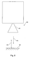
- Fig. 8 shows a level gauge or level sensor according to another embodiment of the present invention.
- Fig. 9 shows a schematic representation of polarization planes of the transmit and receive signals according to an embodiment of the present invention.
- Fig. 10 shows a schematic representation of polarization planes of the transmit and receive signals according to another embodiment of the present invention.
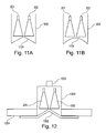
- FIGS. 11A and 11B show an antenna system with inwardly curved cover 1101 of the antennas according to another embodiment of the present invention.
- Fig. 12 shows an antenna system with flush mounting according to another embodiment of the present invention.
- Fig. 1 shows a radar sensor with separate planar antennas 102, 103 for transmitter and receiver.
- the planar antennas 102, 103 are arranged on a printed circuit board 101.
- an electronics module 104 is provided.
- the process temperature is significantly limited because the electronic components are exposed to the full temperature of the container.
- Fig. 2 shows an antenna system with a first horn antenna 201 and a second urine antenna 202, which are arranged side by side in a common housing 203.
- the cross-sectional areas of the antenna horns are here, for example, round or elliptical.
- Fig. 3A shows an antenna system according to another embodiment of the present invention, in which the "normal" horn antennas 201, 202 are arranged inclined to each other.
- the container has, for example, a cylindrical shape whose cross section is adapted to the opening cross sections of the antennas 201, 202.
- Fig. 3B shows a further embodiment of an antenna system in which the two horn antennas 201, 202 are also arranged inclined to each other.
- the common housing 203 is adapted to the inclination of the antennas, that is, for example, converges conically upwards.
- Fig. 4A shows another embodiment of an antenna system according to the present invention, in which two "half" horn antennas 201, 202 are arranged side by side in the housing 203.
- the housing is designed, for example, cylindrical.
- Fig. 4B shows a further embodiment of the present invention, in which the two "half" horn antennas 201, 202 are also arranged side by side and also as in the embodiment of Fig. 4A have a semicircular or semi-elliptical cross section.
- the housing 203 converges upward and is adapted, for example, to the outer shape of the horn antennas 201, 202 by having a circular or elliptical cross section.
- Fig. 5 shows a further embodiment of an antenna system according to another embodiment of the present invention, in which the two horn antennas 201, 202 are arranged directly adjacent to each other, so that they have a common outer shape as in a training normal horn antenna.
- the two horn antennas 201, 202 are designed, for example, with a semicircular or semi-elliptical cross section ("half" horn antennas).
- Fig. 6 shows an antenna system according to another embodiment of the present invention, in which the two horn antennas 201, 202 are executed bent.
- Fig. 7 shows an antenna system according to another embodiment of the present invention, in a view from below, so on the openings of the horn antennas 201, 202.
- the two horn antennas are arranged side by side, twisted to each other.
- the common housing 203 has, for example, an elliptical cross section.
- Figs. 11A and 11B show an antenna system with inwardly curved cover 1101 of the antennas. This design allows condensate, which collects on the front cover to drain to the edge and drain there.
- the curvature 1101 may, for example, be conical or round.
- the inwardly domed cover has the advantage of much higher decoupling (about 15dB better) of the two antennas over the outward bulge (e.g., drip tip in the middle).
- FIG. 12 shows an antenna system with flush mounting.
- the common housing consists of a flange 1201, a plastic cover 1202 and a surrounding housing 1203.
- the connecting piece 1204 forms the connection to the electronics housing (not shown).
- This version is particularly suitable for small containers without nozzles, because the sensor does not protrude into the container and thereby additionally reduces the possible measuring range.
- the two horn antennas are arranged together in a cylindrical, elliptical or conical housing, for example, side by side.
- a preferred solution is the conical antenna housing, since here the diameter at the antenna front edge tapers towards the antenna connection and can thus easily be connected to existing electronics housings.
- the two antennas can have a round, semicircular, elliptical or angular opening cross-section, so that they optimally utilize the area of the antenna housing facing the medium. As a result, the maximum possible antenna gain and the minimum opening angle can be achieved for a given area.
- Advantages are in particular a good decoupling between transmitting and receiving antenna, a compact design of the antenna system, a small "dead zone” and thus good accuracy and sensitivity in the vicinity and a very good suitability for small containers.
- Fig. 9 shows a schematic representation of polarization planes of the transmit and receive signals according to an embodiment of the present invention.
- Reference numerals 901 and 902 show the polarization planes of the electric field of the transmission signal (transmission antenna 201) and the reception signal (reception antenna 202), respectively.
- Fig. 10 shows a schematic representation of polarization planes of the transmit and receive signals according to another embodiment of the present invention.
- Reference numerals 1001 and 1002 show the polarization planes of the electric field of the transmission signal and the reception signal, respectively.
- the polarization planes of the electric field that is to say the transmitting and the receiving polarization
- the transmitting and the receiving polarization can be suitably aligned with one another.
- a parallel alignment of the transmitting and receiving polarization is advantageous.
- the antennae for transmitters and receivers have the same polarization planes.
- the polarization planes 901, 902 lie in a common plane.
- the polarization planes 1001, 1002 lie in separate, parallel planes, which are perpendicular to a connecting line between the centers of the antennas 201, 202.
- Fig. 10 leads to an improved isolation between transmitting and receiving antenna and thus also has low interfering signals (direct coupling over from the transmitter to the receiver) in the near range. This increases the measuring sensitivity in this area.
- the decoupling of the two antennas increases as the distance between the antennas increases. As a result, the coupling between the antennas and thus the ringing is greatly reduced.
- two different antenna variants round horn, half round horn
- the transmission behavior ie the isolation between transmitter and receiver
- Fig. 8 shows a schematic representation of a level radar according to another embodiment of the present invention.
- the fill level radar 800 in this case has a signal generator unit and a receiver circuit. Furthermore, an antenna device 801 (antenna system) according to an embodiment of the present invention is provided.
- the antenna system 801 transmits a transmission signal 802 in the direction of the product surface 804, which is reflected as a received signal 803 from the product surface and detected by the antenna system 801. From this then the level can be determined.
Landscapes
- Physics & Mathematics (AREA)
- Engineering & Computer Science (AREA)
- Radar, Positioning & Navigation (AREA)
- Remote Sensing (AREA)
- Electromagnetism (AREA)
- General Physics & Mathematics (AREA)
- Computer Networks & Wireless Communication (AREA)
- Thermal Sciences (AREA)
- Fluid Mechanics (AREA)
- Radar Systems Or Details Thereof (AREA)
Priority Applications (3)
| Application Number | Priority Date | Filing Date | Title |
|---|---|---|---|
| EP07120998.5A EP2060883B1 (fr) | 2007-11-19 | 2007-11-19 | Tissu d'origine animale biocréé adapté pour être utilisé en tant que substitut de cuir |
| US12/251,989 US20090128396A1 (en) | 2007-11-19 | 2008-10-15 | Filling Level Sensor for Short Measuring Distances |
| CNA2008101776141A CN101441269A (zh) | 2007-11-19 | 2008-11-17 | 用于短测量距离的填充水平传感器 |
Applications Claiming Priority (1)
| Application Number | Priority Date | Filing Date | Title |
|---|---|---|---|
| EP07120998.5A EP2060883B1 (fr) | 2007-11-19 | 2007-11-19 | Tissu d'origine animale biocréé adapté pour être utilisé en tant que substitut de cuir |
Publications (2)
| Publication Number | Publication Date |
|---|---|
| EP2060883A1 true EP2060883A1 (fr) | 2009-05-20 |
| EP2060883B1 EP2060883B1 (fr) | 2016-08-24 |
Family
ID=39326045
Family Applications (1)
| Application Number | Title | Priority Date | Filing Date |
|---|---|---|---|
| EP07120998.5A Active EP2060883B1 (fr) | 2007-11-19 | 2007-11-19 | Tissu d'origine animale biocréé adapté pour être utilisé en tant que substitut de cuir |
Country Status (3)
| Country | Link |
|---|---|
| US (1) | US20090128396A1 (fr) |
| EP (1) | EP2060883B1 (fr) |
| CN (1) | CN101441269A (fr) |
Cited By (5)
| Publication number | Priority date | Publication date | Assignee | Title |
|---|---|---|---|---|
| DE102012104090A1 (de) * | 2012-05-10 | 2013-11-14 | Endress + Hauser Gmbh + Co. Kg | Stapelbare Hornantennenelemente für Antennenanordnungen |
| WO2014051481A1 (fr) | 2012-09-25 | 2014-04-03 | Rosemount Tank Radar Ab | Antenne directionnelle à deux canaux et jauge de niveau à radar doté d'une telle antenne |
| DE102013104699A1 (de) | 2013-05-07 | 2014-11-13 | Endress + Hauser Gmbh + Co. Kg | Vorrichtung zur Bestimmung des Füllstandes mittels einer Helixantenne |
| EP3467448A1 (fr) * | 2017-10-06 | 2019-04-10 | VEGA Grieshaber KG | Appareil de mesure de niveau de remplissage à radar pourvu de puces radar à niveaux différents d'une carte |
| WO2020011596A1 (fr) * | 2018-07-10 | 2020-01-16 | Vega Grieshaber Kg | Système d'antennes radar de niveau de remplissage permettant de mesurer un niveau de remplissage dans un récipient |
Families Citing this family (6)
| Publication number | Priority date | Publication date | Assignee | Title |
|---|---|---|---|---|
| EP2527805B1 (fr) * | 2011-05-27 | 2022-11-30 | VEGA Grieshaber KG | Dispositif d'évaluation et procédé de détermination d'une grandeur caractéristique pour la position d'une surface limite dans un récipient |
| US9046406B2 (en) * | 2012-04-11 | 2015-06-02 | Honeywell International Inc. | Advanced antenna protection for radars in level gauging and other applications |
| WO2017044168A2 (fr) * | 2015-06-16 | 2017-03-16 | King Abdulaziz City Of Science And Technology | Ensemble antenne plane à réseau de phases efficace |
| US10079430B2 (en) * | 2016-01-15 | 2018-09-18 | The United States Of America, As Represented By The Secretary Of The Army | Antenna mount |
| DE102016217614B4 (de) * | 2016-09-15 | 2023-12-14 | Vega Grieshaber Kg | Antennenanordnung |
| CN109818147B (zh) * | 2017-11-20 | 2021-04-02 | 启碁科技股份有限公司 | 号角天线及其天线盖 |
Citations (6)
| Publication number | Priority date | Publication date | Assignee | Title |
|---|---|---|---|---|
| DE2312145A1 (de) * | 1972-03-15 | 1973-09-20 | British Steel Corp | Verfahren und geraet zur entfernungsmessung mit hilfe von mikrowellen |
| EP0444834A2 (fr) | 1990-02-26 | 1991-09-04 | Nkk Corporation | Appareil de mesure de niveau dans un four et antenne associée |
| US5420589A (en) * | 1993-06-07 | 1995-05-30 | Wells; C. T. | System for evaluating the inner medium characteristics of non-metallic materials |
| EP0957371A2 (fr) * | 1998-05-11 | 1999-11-17 | Mannesmann VDO Aktiengesellschaft | Capteur radar |
| EP1674882A1 (fr) | 2004-12-27 | 2006-06-28 | TDK Corporation | Dispositif de radar |
| WO2007042324A1 (fr) * | 2005-10-14 | 2007-04-19 | Vega Grieshaber Kg | Antenne parabolique avec disque de diffusion conique pour radar de detection de niveau |
Family Cites Families (7)
| Publication number | Priority date | Publication date | Assignee | Title |
|---|---|---|---|---|
| US4258321A (en) * | 1978-03-09 | 1981-03-24 | Neale Jr Dory J | Radio geophysical surveying method and apparatus |
| DE19904303A1 (de) * | 1999-01-28 | 2000-08-24 | Bosch Gmbh Robert | Gehäuse für ein elektronisches Gerät in der Mikrowellentechnik |
| US6310574B1 (en) * | 1999-08-05 | 2001-10-30 | Vega Grieshaber Kg | Level transmitter |
| US6661389B2 (en) * | 2000-11-20 | 2003-12-09 | Vega Grieshaber Kg | Horn antenna for a radar device |
| WO2003085365A1 (fr) * | 2002-04-10 | 2003-10-16 | Vega Grieshaber Kg | Appareil de mesure de niveau renfermant de l'equipement electronique et une antenne dans un boitier |
| US20040035352A1 (en) * | 2002-08-23 | 2004-02-26 | Self Kenneth L. | Antenna cover for a mobile communications device |
| US7161553B2 (en) * | 2004-11-04 | 2007-01-09 | Courtney Michael J | Satellite antenna cover |
-
2007
- 2007-11-19 EP EP07120998.5A patent/EP2060883B1/fr active Active
-
2008
- 2008-10-15 US US12/251,989 patent/US20090128396A1/en not_active Abandoned
- 2008-11-17 CN CNA2008101776141A patent/CN101441269A/zh active Pending
Patent Citations (6)
| Publication number | Priority date | Publication date | Assignee | Title |
|---|---|---|---|---|
| DE2312145A1 (de) * | 1972-03-15 | 1973-09-20 | British Steel Corp | Verfahren und geraet zur entfernungsmessung mit hilfe von mikrowellen |
| EP0444834A2 (fr) | 1990-02-26 | 1991-09-04 | Nkk Corporation | Appareil de mesure de niveau dans un four et antenne associée |
| US5420589A (en) * | 1993-06-07 | 1995-05-30 | Wells; C. T. | System for evaluating the inner medium characteristics of non-metallic materials |
| EP0957371A2 (fr) * | 1998-05-11 | 1999-11-17 | Mannesmann VDO Aktiengesellschaft | Capteur radar |
| EP1674882A1 (fr) | 2004-12-27 | 2006-06-28 | TDK Corporation | Dispositif de radar |
| WO2007042324A1 (fr) * | 2005-10-14 | 2007-04-19 | Vega Grieshaber Kg | Antenne parabolique avec disque de diffusion conique pour radar de detection de niveau |
Cited By (11)
| Publication number | Priority date | Publication date | Assignee | Title |
|---|---|---|---|---|
| DE102012104090A1 (de) * | 2012-05-10 | 2013-11-14 | Endress + Hauser Gmbh + Co. Kg | Stapelbare Hornantennenelemente für Antennenanordnungen |
| WO2014051481A1 (fr) | 2012-09-25 | 2014-04-03 | Rosemount Tank Radar Ab | Antenne directionnelle à deux canaux et jauge de niveau à radar doté d'une telle antenne |
| EP2901524A4 (fr) * | 2012-09-25 | 2016-05-25 | Rosemount Tank Radar Ab | Antenne directionnelle à deux canaux et jauge de niveau à radar doté d'une telle antenne |
| DE102013104699A1 (de) | 2013-05-07 | 2014-11-13 | Endress + Hauser Gmbh + Co. Kg | Vorrichtung zur Bestimmung des Füllstandes mittels einer Helixantenne |
| EP3467448A1 (fr) * | 2017-10-06 | 2019-04-10 | VEGA Grieshaber KG | Appareil de mesure de niveau de remplissage à radar pourvu de puces radar à niveaux différents d'une carte |
| CN109632045A (zh) * | 2017-10-06 | 2019-04-16 | Vega格里沙贝两合公司 | 具有不同电路板层级上的雷达芯片的雷达物位测量装置 |
| US11029188B2 (en) | 2017-10-06 | 2021-06-08 | Vega Grieshaber Kg | Radar fill level measurement device comprising radar chips on different planes of a circuit board |
| CN109632045B (zh) * | 2017-10-06 | 2021-07-09 | Vega格里沙贝两合公司 | 具有不同电路板层级上的雷达芯片的雷达物位测量装置 |
| WO2020011596A1 (fr) * | 2018-07-10 | 2020-01-16 | Vega Grieshaber Kg | Système d'antennes radar de niveau de remplissage permettant de mesurer un niveau de remplissage dans un récipient |
| DE102018211422A1 (de) * | 2018-07-10 | 2020-01-16 | Vega Grieshaber Kg | Füllstandradarantennenanordnung zur Messung eines Füllstandes in einem Behälter |
| US11841261B2 (en) | 2018-07-10 | 2023-12-12 | Vega Grieshaber Kg | Fill state radar antenna assembly for measuring the fill state in a container |
Also Published As
| Publication number | Publication date |
|---|---|
| EP2060883B1 (fr) | 2016-08-24 |
| CN101441269A (zh) | 2009-05-27 |
| US20090128396A1 (en) | 2009-05-21 |
Similar Documents
| Publication | Publication Date | Title |
|---|---|---|
| EP2060883B1 (fr) | Tissu d'origine animale biocréé adapté pour être utilisé en tant que substitut de cuir | |
| EP1149432B1 (fr) | Detecteur radar asymetrique a plusieurs faisceaux | |
| DE60214755T2 (de) | Hornantenne für eine Pegelmesseinrichtung | |
| DE19644164A1 (de) | Kraftfahrzeug-Radarsystem | |
| EP2113966A1 (fr) | Capteur radar à plusieurs rayons | |
| DE102017102587A1 (de) | Füllstandsschalter und Verfahren zur Bestimmung eines Grenzstandes eines Mediums in einem Behälter | |
| DE19510484C2 (de) | Füllstandsmesser | |
| WO2007110164A1 (fr) | Transition de guide d'onde avec élément de découplage pour entrées de guide d'onde planes | |
| DE10221856B4 (de) | Einrichtung zur Trennung polarisierter Wellen | |
| EP3511684A1 (fr) | Appareil de mesure de niveau de remplissage | |
| DE202005008528U1 (de) | Messgerät der Prozessmesstechnik mit einer Parabolantenne | |
| WO2002068913A2 (fr) | Dispositif pour determiner ou controler le niveau de remplissage d'un produit de remplissage dans un contenant | |
| EP3165883B1 (fr) | Capteur radar de niveau de remplissage dote de blindage | |
| DE102012112218A1 (de) | Füllstandsmessgerät | |
| DE102021100694A1 (de) | Antennenanordnung für ein topologieerfassendes Radarsystem | |
| EP0634667B1 (fr) | Radar monopulse de dimension réduite | |
| DE102020132964A1 (de) | Füllstandsmessvorrichtung und Verfahren zum in-line Kalibrieren und/oder Verifizieren einer Füllstandsmessvorrichtung | |
| EP2002505B1 (fr) | Jonction de guide d'ondes pour générer des ondes à polarisation circulaire | |
| WO2025002812A1 (fr) | Dispositif radar de mesure de niveau de remplissage pour détecter des niveaux de remplissage dans des récipients | |
| DE102017202214B4 (de) | Verfahren und Anordnung zur Messung von Eigenschaften einer Materialbahn | |
| DE112004001982B4 (de) | Radarfüllstandsmessgerät mit Antennenanordnung zur verbesserten Radarfüllstandsmessung | |
| EP3327408B1 (fr) | Systeme d'analyse de surface d'un materiau de remplissage dans un recipient avec une antenne parabolique permettant de fournir deux caracteristiques directionnelles differentes, et procede de mesure de niveau d'un materiau de remplissage dans un contenant | |
| DE102005031667A1 (de) | Verfahren zur Ermittlung und Überwachung des Füllstands eines Mediums in einem Behälter nach der Laufzeitmessmethode | |
| EP2738564A1 (fr) | Dispositif de localisation pour la localisation d'une source émettant une impulsion micro-ondes haute puissance brève | |
| DE102015101103B4 (de) | Radarsensor für ein Kraftfahrzeug mit gekrümmtem Gehäuseteil, Fahrerassistenzsystem sowie Kraftfahrzeug |
Legal Events
| Date | Code | Title | Description |
|---|---|---|---|
| PUAI | Public reference made under article 153(3) epc to a published international application that has entered the european phase |
Free format text: ORIGINAL CODE: 0009012 |
|
| 17P | Request for examination filed |
Effective date: 20071119 |
|
| AK | Designated contracting states |
Kind code of ref document: A1 Designated state(s): AT BE BG CH CY CZ DE DK EE ES FI FR GB GR HU IE IS IT LI LT LU LV MC MT NL PL PT RO SE SI SK TR |
|
| AX | Request for extension of the european patent |
Extension state: AL BA HR MK RS |
|
| AKX | Designation fees paid |
Designated state(s): DE FR GB |
|
| 17Q | First examination report despatched |
Effective date: 20100203 |
|
| REG | Reference to a national code |
Ref country code: DE Ref legal event code: R079 Ref document number: 502007015048 Country of ref document: DE Free format text: PREVIOUS MAIN CLASS: G01F0023284000 Ipc: G01S0007030000 |
|
| RIC1 | Information provided on ipc code assigned before grant |
Ipc: H01Q 1/42 20060101ALI20151102BHEP Ipc: H01Q 1/22 20060101ALI20151102BHEP Ipc: G01F 23/28 20060101ALI20151102BHEP Ipc: G01S 13/88 20060101ALI20151102BHEP Ipc: H01Q 13/02 20060101ALI20151102BHEP Ipc: G01F 23/284 20060101ALI20151102BHEP Ipc: G01S 7/03 20060101AFI20151102BHEP |
|
| GRAP | Despatch of communication of intention to grant a patent |
Free format text: ORIGINAL CODE: EPIDOSNIGR1 |
|
| INTG | Intention to grant announced |
Effective date: 20151211 |
|
| GRAS | Grant fee paid |
Free format text: ORIGINAL CODE: EPIDOSNIGR3 |
|
| GRAA | (expected) grant |
Free format text: ORIGINAL CODE: 0009210 |
|
| AK | Designated contracting states |
Kind code of ref document: B1 Designated state(s): AT BE BG CH CY CZ DE DK EE ES FI FR GB GR HU IE IS IT LI LT LU LV MC MT NL PL PT RO SE SI SK TR |
|
| RBV | Designated contracting states (corrected) |
Designated state(s): AT BE BG CH CY CZ DE DK EE ES FI FR GB GR HU IE IS IT LI LT LU LV MC MT NL PL PT RO SE SI SK TR |
|
| REG | Reference to a national code |
Ref country code: GB Ref legal event code: FG4D Free format text: NOT ENGLISH |
|
| REG | Reference to a national code |
Ref country code: CH Ref legal event code: EP |
|
| REG | Reference to a national code |
Ref country code: AT Ref legal event code: REF Ref document number: 823564 Country of ref document: AT Kind code of ref document: T Effective date: 20160915 |
|
| REG | Reference to a national code |
Ref country code: IE Ref legal event code: FG4D Free format text: LANGUAGE OF EP DOCUMENT: GERMAN |
|
| REG | Reference to a national code |
Ref country code: DE Ref legal event code: R096 Ref document number: 502007015048 Country of ref document: DE |
|
| REG | Reference to a national code |
Ref country code: FR Ref legal event code: PLFP Year of fee payment: 10 |
|
| REG | Reference to a national code |
Ref country code: LT Ref legal event code: MG4D |
|
| REG | Reference to a national code |
Ref country code: NL Ref legal event code: MP Effective date: 20160824 |
|
| PG25 | Lapsed in a contracting state [announced via postgrant information from national office to epo] |
Ref country code: FI Free format text: LAPSE BECAUSE OF FAILURE TO SUBMIT A TRANSLATION OF THE DESCRIPTION OR TO PAY THE FEE WITHIN THE PRESCRIBED TIME-LIMIT Effective date: 20160824 Ref country code: NL Free format text: LAPSE BECAUSE OF FAILURE TO SUBMIT A TRANSLATION OF THE DESCRIPTION OR TO PAY THE FEE WITHIN THE PRESCRIBED TIME-LIMIT Effective date: 20160824 Ref country code: IT Free format text: LAPSE BECAUSE OF FAILURE TO SUBMIT A TRANSLATION OF THE DESCRIPTION OR TO PAY THE FEE WITHIN THE PRESCRIBED TIME-LIMIT Effective date: 20160824 Ref country code: LT Free format text: LAPSE BECAUSE OF FAILURE TO SUBMIT A TRANSLATION OF THE DESCRIPTION OR TO PAY THE FEE WITHIN THE PRESCRIBED TIME-LIMIT Effective date: 20160824 |
|
| PG25 | Lapsed in a contracting state [announced via postgrant information from national office to epo] |
Ref country code: BE Free format text: LAPSE BECAUSE OF NON-PAYMENT OF DUE FEES Effective date: 20161130 Ref country code: ES Free format text: LAPSE BECAUSE OF FAILURE TO SUBMIT A TRANSLATION OF THE DESCRIPTION OR TO PAY THE FEE WITHIN THE PRESCRIBED TIME-LIMIT Effective date: 20160824 Ref country code: SE Free format text: LAPSE BECAUSE OF FAILURE TO SUBMIT A TRANSLATION OF THE DESCRIPTION OR TO PAY THE FEE WITHIN THE PRESCRIBED TIME-LIMIT Effective date: 20160824 Ref country code: PT Free format text: LAPSE BECAUSE OF FAILURE TO SUBMIT A TRANSLATION OF THE DESCRIPTION OR TO PAY THE FEE WITHIN THE PRESCRIBED TIME-LIMIT Effective date: 20161226 Ref country code: GR Free format text: LAPSE BECAUSE OF FAILURE TO SUBMIT A TRANSLATION OF THE DESCRIPTION OR TO PAY THE FEE WITHIN THE PRESCRIBED TIME-LIMIT Effective date: 20161125 Ref country code: LV Free format text: LAPSE BECAUSE OF FAILURE TO SUBMIT A TRANSLATION OF THE DESCRIPTION OR TO PAY THE FEE WITHIN THE PRESCRIBED TIME-LIMIT Effective date: 20160824 |
|
| PG25 | Lapsed in a contracting state [announced via postgrant information from national office to epo] |
Ref country code: EE Free format text: LAPSE BECAUSE OF FAILURE TO SUBMIT A TRANSLATION OF THE DESCRIPTION OR TO PAY THE FEE WITHIN THE PRESCRIBED TIME-LIMIT Effective date: 20160824 Ref country code: RO Free format text: LAPSE BECAUSE OF FAILURE TO SUBMIT A TRANSLATION OF THE DESCRIPTION OR TO PAY THE FEE WITHIN THE PRESCRIBED TIME-LIMIT Effective date: 20160824 |
|
| REG | Reference to a national code |
Ref country code: DE Ref legal event code: R097 Ref document number: 502007015048 Country of ref document: DE |
|
| PG25 | Lapsed in a contracting state [announced via postgrant information from national office to epo] |
Ref country code: SK Free format text: LAPSE BECAUSE OF FAILURE TO SUBMIT A TRANSLATION OF THE DESCRIPTION OR TO PAY THE FEE WITHIN THE PRESCRIBED TIME-LIMIT Effective date: 20160824 Ref country code: DK Free format text: LAPSE BECAUSE OF FAILURE TO SUBMIT A TRANSLATION OF THE DESCRIPTION OR TO PAY THE FEE WITHIN THE PRESCRIBED TIME-LIMIT Effective date: 20160824 Ref country code: BG Free format text: LAPSE BECAUSE OF FAILURE TO SUBMIT A TRANSLATION OF THE DESCRIPTION OR TO PAY THE FEE WITHIN THE PRESCRIBED TIME-LIMIT Effective date: 20161124 Ref country code: PL Free format text: LAPSE BECAUSE OF FAILURE TO SUBMIT A TRANSLATION OF THE DESCRIPTION OR TO PAY THE FEE WITHIN THE PRESCRIBED TIME-LIMIT Effective date: 20160824 Ref country code: CZ Free format text: LAPSE BECAUSE OF FAILURE TO SUBMIT A TRANSLATION OF THE DESCRIPTION OR TO PAY THE FEE WITHIN THE PRESCRIBED TIME-LIMIT Effective date: 20160824 |
|
| PLBE | No opposition filed within time limit |
Free format text: ORIGINAL CODE: 0009261 |
|
| REG | Reference to a national code |
Ref country code: CH Ref legal event code: PL |
|
| STAA | Information on the status of an ep patent application or granted ep patent |
Free format text: STATUS: NO OPPOSITION FILED WITHIN TIME LIMIT |
|
| PG25 | Lapsed in a contracting state [announced via postgrant information from national office to epo] |
Ref country code: LI Free format text: LAPSE BECAUSE OF NON-PAYMENT OF DUE FEES Effective date: 20161130 Ref country code: CH Free format text: LAPSE BECAUSE OF NON-PAYMENT OF DUE FEES Effective date: 20161130 |
|
| 26N | No opposition filed |
Effective date: 20170526 |
|
| REG | Reference to a national code |
Ref country code: IE Ref legal event code: MM4A |
|
| PG25 | Lapsed in a contracting state [announced via postgrant information from national office to epo] |
Ref country code: SI Free format text: LAPSE BECAUSE OF FAILURE TO SUBMIT A TRANSLATION OF THE DESCRIPTION OR TO PAY THE FEE WITHIN THE PRESCRIBED TIME-LIMIT Effective date: 20160824 |
|
| PG25 | Lapsed in a contracting state [announced via postgrant information from national office to epo] |
Ref country code: LU Free format text: LAPSE BECAUSE OF NON-PAYMENT OF DUE FEES Effective date: 20161130 |
|
| REG | Reference to a national code |
Ref country code: FR Ref legal event code: PLFP Year of fee payment: 11 |
|
| PG25 | Lapsed in a contracting state [announced via postgrant information from national office to epo] |
Ref country code: IE Free format text: LAPSE BECAUSE OF NON-PAYMENT OF DUE FEES Effective date: 20161119 |
|
| REG | Reference to a national code |
Ref country code: AT Ref legal event code: MM01 Ref document number: 823564 Country of ref document: AT Kind code of ref document: T Effective date: 20161119 |
|
| PG25 | Lapsed in a contracting state [announced via postgrant information from national office to epo] |
Ref country code: AT Free format text: LAPSE BECAUSE OF NON-PAYMENT OF DUE FEES Effective date: 20161119 |
|
| REG | Reference to a national code |
Ref country code: BE Ref legal event code: MM Effective date: 20161130 |
|
| PG25 | Lapsed in a contracting state [announced via postgrant information from national office to epo] |
Ref country code: HU Free format text: LAPSE BECAUSE OF FAILURE TO SUBMIT A TRANSLATION OF THE DESCRIPTION OR TO PAY THE FEE WITHIN THE PRESCRIBED TIME-LIMIT; INVALID AB INITIO Effective date: 20071119 Ref country code: CY Free format text: LAPSE BECAUSE OF FAILURE TO SUBMIT A TRANSLATION OF THE DESCRIPTION OR TO PAY THE FEE WITHIN THE PRESCRIBED TIME-LIMIT Effective date: 20160824 |
|
| PG25 | Lapsed in a contracting state [announced via postgrant information from national office to epo] |
Ref country code: TR Free format text: LAPSE BECAUSE OF FAILURE TO SUBMIT A TRANSLATION OF THE DESCRIPTION OR TO PAY THE FEE WITHIN THE PRESCRIBED TIME-LIMIT Effective date: 20160824 Ref country code: IS Free format text: LAPSE BECAUSE OF FAILURE TO SUBMIT A TRANSLATION OF THE DESCRIPTION OR TO PAY THE FEE WITHIN THE PRESCRIBED TIME-LIMIT Effective date: 20160824 Ref country code: MC Free format text: LAPSE BECAUSE OF FAILURE TO SUBMIT A TRANSLATION OF THE DESCRIPTION OR TO PAY THE FEE WITHIN THE PRESCRIBED TIME-LIMIT Effective date: 20160824 |
|
| PG25 | Lapsed in a contracting state [announced via postgrant information from national office to epo] |
Ref country code: MT Free format text: LAPSE BECAUSE OF FAILURE TO SUBMIT A TRANSLATION OF THE DESCRIPTION OR TO PAY THE FEE WITHIN THE PRESCRIBED TIME-LIMIT Effective date: 20160824 |
|
| P01 | Opt-out of the competence of the unified patent court (upc) registered |
Effective date: 20230428 |
|
| PGFP | Annual fee paid to national office [announced via postgrant information from national office to epo] |
Ref country code: GB Payment date: 20231123 Year of fee payment: 17 |
|
| PGFP | Annual fee paid to national office [announced via postgrant information from national office to epo] |
Ref country code: FR Payment date: 20231123 Year of fee payment: 17 |
|
| PGFP | Annual fee paid to national office [announced via postgrant information from national office to epo] |
Ref country code: DE Payment date: 20241119 Year of fee payment: 18 |
|
| GBPC | Gb: european patent ceased through non-payment of renewal fee |
Effective date: 20241119 |
|
| PG25 | Lapsed in a contracting state [announced via postgrant information from national office to epo] |
Ref country code: GB Free format text: LAPSE BECAUSE OF NON-PAYMENT OF DUE FEES Effective date: 20241119 |
|
| PG25 | Lapsed in a contracting state [announced via postgrant information from national office to epo] |
Ref country code: FR Free format text: LAPSE BECAUSE OF NON-PAYMENT OF DUE FEES Effective date: 20241130 |