EP2060969A2 - Berührungsvorrichtung und Verfahren zur Bestimmung des Berührungsmodus davon - Google Patents
Berührungsvorrichtung und Verfahren zur Bestimmung des Berührungsmodus davon Download PDFInfo
- Publication number
- EP2060969A2 EP2060969A2 EP08167920A EP08167920A EP2060969A2 EP 2060969 A2 EP2060969 A2 EP 2060969A2 EP 08167920 A EP08167920 A EP 08167920A EP 08167920 A EP08167920 A EP 08167920A EP 2060969 A2 EP2060969 A2 EP 2060969A2
- Authority
- EP
- European Patent Office
- Prior art keywords
- electrode
- conductive layer
- touch
- electrically coupled
- resistor
- Prior art date
- Legal status (The legal status is an assumption and is not a legal conclusion. Google has not performed a legal analysis and makes no representation as to the accuracy of the status listed.)
- Withdrawn
Links
Images





Classifications
-
- G—PHYSICS
- G06—COMPUTING OR CALCULATING; COUNTING
- G06F—ELECTRIC DIGITAL DATA PROCESSING
- G06F3/00—Input arrangements for transferring data to be processed into a form capable of being handled by the computer; Output arrangements for transferring data from processing unit to output unit, e.g. interface arrangements
- G06F3/01—Input arrangements or combined input and output arrangements for interaction between user and computer
- G06F3/03—Arrangements for converting the position or the displacement of a member into a coded form
- G06F3/041—Digitisers, e.g. for touch screens or touch pads, characterised by the transducing means
- G06F3/045—Digitisers, e.g. for touch screens or touch pads, characterised by the transducing means using resistive elements, e.g. a single continuous surface or two parallel surfaces put in contact
-
- G—PHYSICS
- G06—COMPUTING OR CALCULATING; COUNTING
- G06F—ELECTRIC DIGITAL DATA PROCESSING
- G06F3/00—Input arrangements for transferring data to be processed into a form capable of being handled by the computer; Output arrangements for transferring data from processing unit to output unit, e.g. interface arrangements
- G06F3/01—Input arrangements or combined input and output arrangements for interaction between user and computer
- G06F3/03—Arrangements for converting the position or the displacement of a member into a coded form
- G06F3/041—Digitisers, e.g. for touch screens or touch pads, characterised by the transducing means
- G06F3/0416—Control or interface arrangements specially adapted for digitisers
- G06F3/04164—Connections between sensors and controllers, e.g. routing lines between electrodes and connection pads
Definitions
- the present invention relates to a touch display device, and more particularly, relates to a touch display device capable of identifying a touch pen operation mode and a finger operation mode.
- touch devices provide intuitive operations for users to input data and select functions; therefore, touch devices have been widely applied in many kinds of electronic devices, especially touch display devices.
- a touch display device comprising a resistance touch panel is cost efficient and easy to use; therefore, resistance touch panels are widely used.
- the touch display device having resistive touch panels does not provide control modules for determining a touch pen operation mode or a finger operation mode; therefore, the touch screen devices has the same control effect between the touch pen operation mode and the finger operation mode. If the touch display device can identify different operation modes, the control methods and effects of the touch display device will be more varied.
- the present invention provides a touch device comprising a resistive touch panel, a measuring unit, a resistor, and a control module.
- the resistive touch panel comprises a first conductive layer and a second conductive layer.
- the first conductive layer is capable of contacting the second conductive layer when an input object is pressed.
- the resistor electrically couples between the control module and the first conductive layer.
- the measuring unit is used for measuring a voltage value across the resistor.
- the control module is electrically coupled with the resistor and the measuring unit. When the first conductive layer contacts the second conductive layer, the measuring unit outputs a measured voltage value.
- the touch pen operation mode is activated when the measured voltage value is smaller than a default value; the finger operation mode is activated when the measured voltage value is larger than the default value.
- the present invention provides a method of determining a touch mode for a resistive touch panel capable of being operated in a touch pen operation mode or a finger operation mode, the method comprising: when the first conductive layer contacts the second conductive layer, measuring a voltage across the resistor to obtain a measured voltage; determining whether the measured voltage is smaller than a default value; activating the touch pen operation mode if the measured voltage is smaller than the default value; activating the finger operation mode if the measured voltage is larger than the default value.
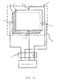
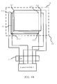
- the touch device in the present invention can be a touch display device, please refer to FIG. 1A and FIG. 1B .
- FIG. 1A and FIG. 1B are structure drawings of a touch device according to the embodiment of the present invention.
- the touch display device 10 of the present invention can be operated under a touch pen operation mode or a finger operation mode.
- the touch display device 10 includes a control module 21, a measuring unit 22, a resistive touch panel 30, and a resistor R.
- the control module 21 can be a chip; the control module 21 is electrically coupled with the measuring unit 22.
- the control module 21 uses the measuring unit 22 to measure the voltage value across the resistor R.
- the measuring unit 22 can also be implemented in the control module 21.
- the resistive touch panel 30 is, but is not limited, to a four-wire resistive touch panel.
- the resistive touch panel 30 comprises a first conductive layer 31 and a second conductive layer 32.
- the first conductive layer 31 comprises a first electrode 311 and a second electrode 312.
- the first electrode 311 and the second electrode 312 respectively connect to a power source V or a ground G (as shown in FIG. 3A and FIG. 4A ) to create a voltage difference between the first electrode 311 and the second electrode 312 to form a uniform electric field.
- the first electrode 311 and the second electrode 312 electrically couple with the control module 21 respectively, with the resistor R being electrically coupled between the first electrode 311 and the control module 21.
- the second conductive layer 32 comprises a third electrode 321 and a fourth electrode 322.
- the third electrode 321 and the fourth electrode 322 electrically couple with the control module 21 respectively.
- the resistor R can be electrically coupled with the second electrode 312 or electrically coupled with the third electrode 321 or the fourth electrode 322 on the second conductive layer 32 (as shown in FIG. 3B and FIG. 4B ).
- the first electrode 311, the second electrode 312, the third electrode 321, and the fourth electrode 322 are all conductive wires to form the four-wire resistive touch panel 30.
- the third electrode 321 and the fourth electrode 322 are disposed at opposite side of the second conductive layer 32 respectively to measure an X-axis coordinate value on the resistive touch panel 30.
- the third electrode 321 and the fourth electrode 322, which are disposed on opposite sides of the second conductive layer 32 can also have a voltage difference and form a uniform electric field. Therefore, the first electrode 311 and the second electrode 312, on opposite side of the first conductive layer 31, are used to measure the Y coordinate value.
- the configuration of the X-axis and the Y-axis of the four-wire resistive touch panel and their working theory are well known by those in the related field, so no further description will be provided.
- An input object such as a finger or a touch pen can press the first conductive layer 31 to contact the second conductive layer 32.
- a short circuit is formed when the first conductive layer 31 contacts the second conductive layer 32, causing a drop in voltage. Therefore, whether the first conductive layer 31 contacts the second conductive layer 32 is determined by measuring the voltage values of the third electrode 321 or the fourth electrode 322.
- the measuring unit 22 measures the voltage value of the resistor R to obtain a measured voltage value.
- the measured voltage value is larger than a default value, which means a finger is pressing the first conductive layer 31 to contact the second conductive layer 32, the finger operation mode is thus activated.
- the touch pen operation mode is activated.
- the default value can be set by the control module 21, it can also be set by other means as long as it falls within the scope of the present invention. The method of determining whether the touch pen operation mode or the finger operation mode is activated will be described in detail below.
- resistors R is not limited to one, and that any two of the electrodes can be used to couple with different resistors in the present invention.
- the resistive touch panel also can be a five-wire resistive touch panel 30'.
- the resistive touch panel 30' comprises a second conductive layer 31' and a first conductive layer 32'.
- the second conductive layer 31' comprises a sensing electrode 311'
- the first conductive layer 32' comprises a first electrode 321', a second electrode 322', a third electrode 323', and a fourth electrode 324'.
- the first electrode 321' and the second electrode 322' couple with the power source V or the ground G respectively (as shown in FIG. 5A and FIG. 5B ) in order to cause a voltage difference between the first electrode 321' and the second electrode 322' and form a uniform electric field.
- the first electrode 321' and the second electrode 322' electrically couple with the control module 21 respectively, and a resistor R' is coupled between the first electrode 321' and the control module 21.
- the resistor R' is not coupled with only the first electrode 321' on the first conductive layer 32'; the resistor R' can also be electrically coupled with the second electrode 322', the third electrode 323', or the fourth electrode 324' in the present invention.
- the sensing electrode 311', the first electrode 321', the second electrode 322', the third electrode 323', and the fourth electrode 324' are conductive wires to form the five-wire resistive touch panel 30'.
- the first electrode 321', the second electrode 322', the third electrode 323', and the fourth electrode 324' can be utilized for measuring the X-axis coordinate value and the Y-axis coordinate value of the resistive touch panel 30'.
- the configuration of the X axis and the Y axis and the working theory of the five-wire resistive touch panel are well known by those in the related field; therefore, they will not be described further.
- An input object such as a finger or a touch pen can press the second conductive layer 31' and the first conductive layer 32' such that they contact each other.
- a short circuit is formed, thus generating a drop in voltage. Therefore, whether the second conductive layer 31' contacts the first conductive layer 32' is determined by measuring the voltage value of the sensing electrode 311'.
- the measuring unit 22 measures the voltage value of the resistor R' to obtain a measured voltage value.
- the finger operation mode is activated.
- the touch pen operation mode is activated.
- the default value can be set by the control module 21, it can also be set by other means as long as it falls within the scope of the present invention. The method of determining whether the touch pen operation mode or the finger operation mode is activated will be described in detail below.
- resistors R' connected to the resistive touch panel 30' is not limited to one. Two of the electrodes can be selected to be connected to different resistors in the present invention.
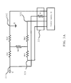
- FIG. 3A is an equivalent circuit diagram of the touch display device according to a first embodiment of the touch pen operation mode
- FIG. 3B is a n equivalent circuit diagram of the touch display device according to a second embodiment of the touch pen operation mode
- FIG. 4A is a n eq uivalent circuit diagram of the touch display device according to the first embodiment of the finger operation mode
- FIG. 4B is an equivalent circuit diagram of the touch display device according to the second embodiment of the finger operation mode.
- the four-wire resistive touch panel 30 is used for illustrating the method of determining touch mode, the method can use devices other than the four-wire resistive touch panel 30 to determine touch mode.
- step 201 determining whether the first conductive layer contacts the second conductive layer.
- the control module 21 controls two electrodes of the resistive touch panel 30 to be electrically coupled with the power source and the ground, and then the voltage of another electrode is measured to determine whether a voltage drop has been generated.
- the first conductive layer 31 and the second conductive layer 32 will form a plurality of equivalent resistors Ra1, Ra2, Rb1, and Rb2, respectively.
- the connect area between the first conductive layer 31 and the second conductive layer 32 also forms an equivalent resistor Rz1.
- the control module 21 controls the first electrode 311 of the first conductive layer 31 to be electrically coupled with the power source V and the second electrode 312 to be electrically coupled with the ground G, and then determines whether there is a voltage drop at the third electrode 321 of the second conductive layer 32. If the first conductive layer 31 does not contact the second conductive layer 32, the equivalent circuit between the two conductive layers is broken; therefore, no voltage drop is present at the third electrode 321. The control module 21 can determine whether the first conductive layer 31 contacts the second conductive layer 32 by the above method.
- the above method is just one example of the present invention.
- the third electrode 321 also can be electrically coupled with the power source V, and the fourth electrode 322 also can be electrically coupled with the ground G. Therefore, the present invention is not limited to the circuit connections illustrated in the figures.
- step 202 when the first conductive layer contacts the second conductive layer, measuring a voltage value across the resistor to obtain a measured voltage value.
- control module 21 uses the measuring unit 22 to measure a voltage value across the resistor R to obtain the measured voltage value.
- step 203 determining whether the measured voltage is larger than a default value.
- the control module 21 determines whether the measured voltage is larger than a default value, wherein the default value can be set by the control module 21; however, the default value can also be set by other means.
- the contact area between the first conductive layer 31 and the second conductive layer 32 is very small; the equivalent circuit is shown in FIG. 3A .
- the resistance of the equivalent resistor from the first electrode 311 to the second electrode 312 is equal to the equivalent resistor Ra1 plus the equivalent resistor Ra2.
- the contact area between the first conductive layer 31 and the second conductive layer 32 is larger than that area in the case when the touch pen is used; the equivalent circuit is shown in FIG. 4A .
- the resistance of the equivalent resistor from the first electrode 311 to the second electrode 312 is equal to that of treating the plurality of equivalent resistors Ra1 to Ran and the plurality of equivalent resistors Rb1 to Rbn and the plurality of equivalent resistors Rz1 to Rzn in parallel connection.
- the resistance of the equivalent resistor from the first electrode 311 to the second electrode 312 is smaller than the equivalent resistor when the user uses a touch pen to touch the resistive touch panel 30.
- the default value can be set to be a value between the measured voltage value obtained when a finger is touching the resistive touch panel 30 and the measured voltage value obtained when a touch pen is touching the resistive touch panel 30.
- the measuring unit 22 is used for measuring the measured voltage value across the resistor R and comparing it with the default value; thus it is viable to determine whether the resistive touch panel 30 is touched by a finger or a touch pen.
- the resistor R can be electrically coupled with the second electrode 312 on the first conductive layer 31; alternatively, as shown in the second embodiment in FIG. 3B and FIG. 4B , the resistor R can be electrically coupled with the third electrode 321 or the fourth electrode 322 on the second conductive layer 32.
- the measuring unit 22 obtains the measured voltage value across the resistor R to determine whether the resistive touch panel 30 is touched by a finger or a touch pen.
- the method of determining the touch mode by using the resistor R electrically coupled with the third electrode 321 or the fourth electrode 322 on the second conductive layer 32 is similar to that of using the resistor R electrically coupled with the first electrode 311 or the second electrode 312 on the first conductive layer 32; therefore it will not be described further. From the above, when the measured voltage value is smaller than the default value, the equivalent resistor between the first electrode 311 and the second electrode 312 is larger, and then step 204 is performed: activating the touch pen operation mode.
- control module 21 directly activates the touch pen operation mode.
- step 205 activating the finger operation mode.
- control module 21 directly activates the finger operation mode.
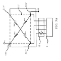
- FIG. 5A is an equivalent circuit diagram of the five-wire resistive touch panel 30' in the touch pen operation mode according to the present invention
- FIG. 5B is an equivalent circuit diagram of the five-wire resistive touch panel 30' in the finger operation mode according to the present invention.
- a resistor R' is connected between the first electrode 321' on the first conductive layer 32' and the control module 21.
- the first electrode 321' and the second electrode 322' are electrically coupled with the power source V or the ground G respectively.
- the resistance of the equivalent resistor between the first electrode 321' and the second electrode 322' is smaller than that of the equivalent resistor in the touch pen operation mode.
- the measured voltage value across the resistor R' is smaller than the default value.
- the touch pen touches the resistive touch panel 30'.
- the touch mode can be determined by electrically coupling the resistor R' with the second electrode 322', the third electrode 323', or the fourth electrode 324' to obtain the voltage value across the resistor R'; however, other methods can be used for determining the voltage value across the resistor R'.
- the method of determining the touch mode for the five-wire resistive touch panel 30' is the same as that for the four-wire resistive touch panel 30; therefore, it will not be described further.
- resistive touch panel 30' it is viable to use the resistive touch panel 30' to determine whether it is in the touch pen operation mode or the finger operation mode.
- FIG. 6 is an illustration of an electronic device comprising the touch display device according to the present invention.
- the touch display device 10 can be installed on the electronic device 40 for users to operate the electronic device 40.
- the electronic device 40 can be, but is not limited to, a tablet PC, a cellular phone, or a personal data assistant.
- the touch display device 10 can switch the touch mode to the touch pen operation mode or the finger operation mode to achieve different operation effects.
- the touch screen device 10 can be implemented to draw thinner lines in the touch pen operation mode and draw thicker lines in the finger operation mode.
- the electronic device 40 can provide more control choices for the user.
Landscapes
- Engineering & Computer Science (AREA)
- General Engineering & Computer Science (AREA)
- Theoretical Computer Science (AREA)
- Human Computer Interaction (AREA)
- Physics & Mathematics (AREA)
- General Physics & Mathematics (AREA)
- Position Input By Displaying (AREA)
Applications Claiming Priority (1)
| Application Number | Priority Date | Filing Date | Title |
|---|---|---|---|
| CN2007101669535A CN101430630B (zh) | 2007-11-08 | 2007-11-08 | 触控装置及其判断触控方式的方法 |
Publications (2)
| Publication Number | Publication Date |
|---|---|
| EP2060969A2 true EP2060969A2 (de) | 2009-05-20 |
| EP2060969A3 EP2060969A3 (de) | 2010-06-02 |
Family
ID=40336444
Family Applications (1)
| Application Number | Title | Priority Date | Filing Date |
|---|---|---|---|
| EP08167920A Withdrawn EP2060969A3 (de) | 2007-11-08 | 2008-10-30 | Berührungsvorrichtung und Verfahren zur Bestimmung des Berührungsmodus davon |
Country Status (2)
| Country | Link |
|---|---|
| EP (1) | EP2060969A3 (de) |
| CN (1) | CN101430630B (de) |
Families Citing this family (5)
| Publication number | Priority date | Publication date | Assignee | Title |
|---|---|---|---|---|
| CN101593068B (zh) * | 2009-06-29 | 2011-07-13 | 华硕电脑股份有限公司 | 电阻式触控面板及其接触点型态的检测方法 |
| CN102436332A (zh) * | 2010-09-29 | 2012-05-02 | 汉王科技股份有限公司 | 一种触控方法及装置 |
| CN103197808B (zh) * | 2012-01-09 | 2016-08-17 | 联想(北京)有限公司 | 响应电容式触摸屏输入的方法、装置及电子设备 |
| CN106940608B (zh) * | 2017-03-07 | 2020-06-16 | Oppo广东移动通信有限公司 | 一种显示屏的控制方法、显示屏及电子设备 |
| CN107168559A (zh) * | 2017-06-06 | 2017-09-15 | 深圳市泰衡诺科技有限公司 | 移动终端触控笔状态检测装置和触控笔 |
Family Cites Families (5)
| Publication number | Priority date | Publication date | Assignee | Title |
|---|---|---|---|---|
| US4687885A (en) * | 1985-03-11 | 1987-08-18 | Elographics, Inc. | Electrographic touch sensor with Z-axis capability |
| US5159159A (en) * | 1990-12-07 | 1992-10-27 | Asher David J | Touch sensor and controller |
| CN2655331Y (zh) * | 2003-10-22 | 2004-11-10 | 仁宝电脑工业股份有限公司 | 电子装置的触控输入装置 |
| CN100405279C (zh) * | 2004-07-09 | 2008-07-23 | 义隆电子股份有限公司 | 整合图形输入功能的电容式触控板 |
| JP4377343B2 (ja) * | 2005-01-31 | 2009-12-02 | 株式会社東海理化電機製作所 | タッチ操作入力装置 |
-
2007
- 2007-11-08 CN CN2007101669535A patent/CN101430630B/zh active Active
-
2008
- 2008-10-30 EP EP08167920A patent/EP2060969A3/de not_active Withdrawn
Also Published As
| Publication number | Publication date |
|---|---|
| EP2060969A3 (de) | 2010-06-02 |
| CN101430630A (zh) | 2009-05-13 |
| CN101430630B (zh) | 2010-12-08 |
Similar Documents
| Publication | Publication Date | Title |
|---|---|---|
| EP2056188A2 (de) | Berührungsanzeigevorrichtung und Verfahren zur Bestimmung des Berührungsmodus davon | |
| US20090120695A1 (en) | Touch Device and Method of Determining Touch Mode Thereof | |
| EP0917090B1 (de) | Kontakteingabeunterscheidung | |
| EP2194453B1 (de) | Tragbare elektronische Vorrichtung und Verfahren zum Aufwecken derselben aus dem Schlafmodus mittels Berührungsbildschirm | |
| TWI398800B (zh) | 觸控面板及其輸出方法 | |
| CN104020911A (zh) | 一种内嵌式触摸屏及显示装置 | |
| CN105404430B (zh) | 3d压感触摸屏及其制造方法以及3d压感触控实现方法 | |
| CN101526679A (zh) | 触控液晶显示装置 | |
| TW200917111A (en) | Resistive type multi-touch control panel and its detection method | |
| EP2060969A2 (de) | Berührungsvorrichtung und Verfahren zur Bestimmung des Berührungsmodus davon | |
| CN101191915A (zh) | 液晶显示面板 | |
| US20130100069A1 (en) | Touch sensing device and method thereof | |
| CN101424994B (zh) | 触控显示装置及判断触控方式的方法 | |
| CN204719367U (zh) | 一种液晶显示面板及显示装置 | |
| CN102236458A (zh) | 触控式电子装置及其相关组装方法 | |
| TWI515632B (zh) | 隨觸即用輸入裝置以及操作方法 | |
| CN101464767A (zh) | 触控面板 | |
| CN106406588A (zh) | 触控显示装置 | |
| US20180259803A1 (en) | Electronic device with touch function and operation method thereof | |
| CN204833207U (zh) | 触控显示装置 | |
| CN101655760A (zh) | 电阻式触摸屏屏体、触摸屏控制器及多触摸点识别方法 | |
| CN102033636B (zh) | 触控模块的控制系统 | |
| JP5520034B2 (ja) | タッチパネル及び座標位置検出方法 | |
| JP2001043003A (ja) | タッチパネル入力装置 | |
| TWI628561B (zh) | 觸控系統及其控制方法 |
Legal Events
| Date | Code | Title | Description |
|---|---|---|---|
| PUAI | Public reference made under article 153(3) epc to a published international application that has entered the european phase |
Free format text: ORIGINAL CODE: 0009012 |
|
| AK | Designated contracting states |
Kind code of ref document: A2 Designated state(s): AT BE BG CH CY CZ DE DK EE ES FI FR GB GR HR HU IE IS IT LI LT LU LV MC MT NL NO PL PT RO SE SI SK TR |
|
| AX | Request for extension of the european patent |
Extension state: AL BA MK RS |
|
| RAP1 | Party data changed (applicant data changed or rights of an application transferred) |
Owner name: ASUSTEK COMPUTER INC. |
|
| PUAL | Search report despatched |
Free format text: ORIGINAL CODE: 0009013 |
|
| AK | Designated contracting states |
Kind code of ref document: A3 Designated state(s): AT BE BG CH CY CZ DE DK EE ES FI FR GB GR HR HU IE IS IT LI LT LU LV MC MT NL NO PL PT RO SE SI SK TR |
|
| AX | Request for extension of the european patent |
Extension state: AL BA MK RS |
|
| RIC1 | Information provided on ipc code assigned before grant |
Ipc: G06F 3/041 20060101ALI20100429BHEP Ipc: G06F 3/045 20060101AFI20090213BHEP |
|
| AKY | No designation fees paid | ||
| STAA | Information on the status of an ep patent application or granted ep patent |
Free format text: STATUS: THE APPLICATION IS DEEMED TO BE WITHDRAWN |
|
| 18D | Application deemed to be withdrawn |
Effective date: 20101203 |
|
| REG | Reference to a national code |
Ref country code: DE Ref legal event code: R108 Effective date: 20110503 |