EP2061009B1 - Segmentation de mouvement itérative - Google Patents
Segmentation de mouvement itérative Download PDFInfo
- Publication number
- EP2061009B1 EP2061009B1 EP09152112A EP09152112A EP2061009B1 EP 2061009 B1 EP2061009 B1 EP 2061009B1 EP 09152112 A EP09152112 A EP 09152112A EP 09152112 A EP09152112 A EP 09152112A EP 2061009 B1 EP2061009 B1 EP 2061009B1
- Authority
- EP
- European Patent Office
- Prior art keywords
- image
- hidden
- parameter
- learning
- images
- Prior art date
- Legal status (The legal status is an assumption and is not a legal conclusion. Google has not performed a legal analysis and makes no representation as to the accuracy of the status listed.)
- Not-in-force
Links
Images


Classifications
-
- G—PHYSICS
- G06—COMPUTING OR CALCULATING; COUNTING
- G06T—IMAGE DATA PROCESSING OR GENERATION, IN GENERAL
- G06T7/00—Image analysis
- G06T7/20—Analysis of motion
- G06T7/215—Motion-based segmentation
-
- G—PHYSICS
- G06—COMPUTING OR CALCULATING; COUNTING
- G06V—IMAGE OR VIDEO RECOGNITION OR UNDERSTANDING
- G06V40/00—Recognition of biometric, human-related or animal-related patterns in image or video data
- G06V40/20—Movements or behaviour, e.g. gesture recognition
-
- G—PHYSICS
- G06—COMPUTING OR CALCULATING; COUNTING
- G06T—IMAGE DATA PROCESSING OR GENERATION, IN GENERAL
- G06T7/00—Image analysis
- G06T7/20—Analysis of motion
- G06T7/277—Analysis of motion involving stochastic approaches, e.g. using Kalman filters
-
- G—PHYSICS
- G06—COMPUTING OR CALCULATING; COUNTING
- G06T—IMAGE DATA PROCESSING OR GENERATION, IN GENERAL
- G06T2207/00—Indexing scheme for image analysis or image enhancement
- G06T2207/10—Image acquisition modality
- G06T2207/10016—Video; Image sequence
-
- G—PHYSICS
- G06—COMPUTING OR CALCULATING; COUNTING
- G06T—IMAGE DATA PROCESSING OR GENERATION, IN GENERAL
- G06T2207/00—Indexing scheme for image analysis or image enhancement
- G06T2207/30—Subject of image; Context of image processing
- G06T2207/30241—Trajectory
Definitions
- the present invention relates to an image processing method and an image processing device for simultaneously extracting, from plural images, a background image, at least two or more object images, the shape of each of the object images, and the motion of each of the object images.
- Non-patent document 1 Chris Stauffer and Eric Grimson, "Adaptive Background Mixture Models for Real-time Tracking," IEEE Computer Society Conference Computer Vision and Pattern Recognition, pp.246-252, 1999 ) is capable of probabilistically modeling temporal variations in pixels to perform background differentiation which flexibly supports temporal variations in pixels. This technique enables the background image and an object image to be separated from each other in a reliable manner.
- Non-patent document 2 John Winn and Andrew Blake, “Generative Affine Localisation and Tracking", Neural Information Processing Systems, No.17, pp.1505-1512, 2004
- Non-patent document 3 John Winn and Christopher Bishop, “Variational Message Passing", Journal of Machine Learning Research, Vol. 6, pp. 661-694, 2005
- plural parameters defined as hidden parameters are extracted through joint optimization, using images as inputs.
- This technique enables robust extraction of parameters since plural hidden parameters act in a complementary manner even in the case where noise has occurred or the shape of an object has changed.
- This technique has another advantage in that there is no need to perform parameter tuning such as setting a threshold or weighting an energy function in the background differentiation process.
- Non-patent documents 1 to 3 have a problem of being unable to simultaneously extract plural objects and the motion of each of such objects in a reliable manner.
- Non-patent document 1 is a technique for separating the background image from another object, and thus when plural objects exist in the image, it is not possible to extract them as individual objects. In order to be able to do so, this technique requires the additional use of a segmentation technique that utilizes information about the objects, such as their colors and motion.
- Non-patent documents 2 and 3 is capable of simultaneously extracting plural hidden parameters from image information only.
- the larger the number of objects included in an image the more the number of hidden parameters that should be solved.
- the number of hidden parameters increases due to camera motion as well as a motion parameter for adapting to complexity in motion and an image degradation parameter for modeling degradation in image quality for the purpose of improving image quality.
- the use of these parameters means that there is a further expansion of the search space. This results in local minima and thus there is a higher risk of being unable to obtain a desired solution.
- the use of this technique to extract two or more object images ends up extracting plural objects as one object that is at a local minimum.
- US6826292B discloses a system that tracks one or more moving objects in a sequence of video images employing a dynamic layer representation to represent the objects that are being tracked.
- the present invention has an object of providing an image processing method and an image processing device capable of simultaneously extracting, from plural images, a background image, at least two or more object images, the shape of each of the object images, and the motion of each of the object images, without resulting in local minima, that is, in a reliable manner.
- the present invention is an image processing method of simultaneously extracting a background image, at least two object images, a shape of each object image and motion of each object image, each of which are defined as hidden parameters, from among plural images, said image processing method comprising:
- the above-described method, device, and the like make it possible to simultaneously extract, from plural images, a background image, at least two or more object images, the shape of each of the object images, and the motion of each of the object images, without resulting in local minima, that is, in a reliable manner. Since local minima can be avoided, another hidden parameter may be employed in addition, such as a camera motion parameter.
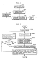
- FIG. 1 is a diagram showing the structure of the image processing device in the first comparative example.
- the image processing device in FIG. 1 is a device that simultaneously extracts the following elements defined as hidden parameters from plural images in a reliable manner: a background image, at least two or more object images, the shape of each of the object images, and the motion of each of the object images.
- the image processing device includes an image input unit 101, a hidden parameter estimation unit 102, a constraint enforcement parameter learning unit 103, a complementary learning unit 104, and an output unit 105.
- the image input unit 101 is a processing unit that accepts the input of plural images. Here, these plural images are not necessarily inputted in a time series.
- the hidden parameter estimation unit 102 is a processing unit that defines, as hidden parameters, the background image, at least two or more object images, the shape of each of the object images, and the motion of each of the object images included in the inputted plural images, and estimates hidden parameters through iterative learning, based on the plural images and constraint enforcement parameters, each of which indicates at least one constraint on a hidden parameter.
- the constraint enforcement parameter learning unit 103 is a processing unit that learns constraint enforcement parameters related to the hidden parameters, using, the estimation results obtained by the hidden parameter estimation unit 102 as training signals.
- the constraint enforcement parameter learning unit 103 learns constraint enforcement parameters related to objects, such as the size of each object image area, the color of each object image, the motion of pixels included in each object image, and the like. Since the constraint enforcement parameter learning unit 103 learns constraint enforcement parameters, using the estimation results obtained by the hidden parameter estimation unit 102 as training signals, it is possible for the constraint enforcement parameter learning unit 103 to carry out automatic learning of constraint enforcement parameters without requiring training signals. For this reason, there is no need to provide knowledge about a scene in advance, and thus there is no limit of applicable scenes.
- the complementary learning unit 104 is a processing unit that causes the following operations to be iteratively performed: estimation of hidden parameters performed by the hidden parameter estimation unit 102 based on constraint enforcement parameters learned by the constraint enforcement parameter learning unit 103; and learning of constraint enforcement parameters performed by the constraint enforcement parameter learning unit 103 based on the results of hidden parameter estimation obtained by the hidden parameter estimation unit 102. More specifically, the complementary learning unit 104 sends, to the hidden parameter estimation unit 102, object-related constraint enforcement parameters learned by the constraint enforcement parameter learning unit 103. Then, the hidden parameter estimation unit 102 extracts hidden parameters again, using the constraint enforcement parameters sent from the complementary learning unit 104. By iteratively performing these operations, it is possible to simultaneously extract a background image, at least two or more object images, the shape of each of the object images, and the motion of each of the object images defined as hidden parameters, while avoiding local minima.
- the output unit 105 is a processing unit that outputs the hidden parameters estimated by the hidden parameter estimation unit 102 after the iterative learning is carried out by the complementary learning unit 104.
- the output unit 105 outputs to the outside the background image, at least two or more object images, the shape of each of the object images, and the motion of each of the object images, which have been simultaneously extracted by the present image processing device, as the results of the processes performed by the present device.
- each of the constituent elements of the image processing device may be implemented in the form of software such as a program executed on a computer having a CPU, a RAM, a ROM, an I/O port, a hard disk, a display, and the like, or may be implemented in the form of hardware such as an electronic circuit.
- software such as a program executed on a computer having a CPU, a RAM, a ROM, an I/O port, a hard disk, a display, and the like
- hardware such as an electronic circuit.
- the image input unit 101 accepts plural input images.
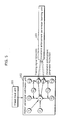
- each input image x301 is composed of a noise ⁇ 302, a background b 303, an image f 1 304 of an object 1, an image f 2 305 of an object 2, motion T 1 306 of the object 1, motion T 2 307 of the object 2, a probability of shape ⁇ 1 308 of the object 1, a probability of shape ⁇ 2 309 of the object 1, a shape m 1 , 310 of the object 1, and a shape m 2 311 of the object 2.
- the noise ⁇ 302, the background b 303, the image f 1 304 of the object 1, the image f 2 305 of the object 2, the motion T 1 306 of the object 1, the motion T 2 307 of the object 2, the probability of shape ⁇ 1 308 of the object 1, the probability of shape ⁇ 2 309 of the object 2, the shape m 1 310 of the object 1, and the shape m 2 311 of the object 2 are all hidden parameters.
- an image f i of an object, a probability of shape ⁇ i of the object, motion T i of the object, and a shape m i of the object are simply added.
- each input image x301 is modeled as a Gaussian distribution
- b , f , m , T , ⁇ N ⁇ x k
- T 2 ⁇ f 2 k , ⁇ f ⁇ 2 - 1 ⁇ m 2 ⁇ N ⁇ x k
- T 1 ⁇ f 1 k , ⁇ f ⁇ 1 - 1 ⁇ m 1 ⁇ N ⁇ x k
- b k , ⁇ b - 1 ⁇ m 0
- N denotes a Gaussian distribution
- the present comparative example is described with the assumption that the noise ⁇ 302 is modeled as a Gamma distribution, the background b 303, the image f 1 304 of the object 1 and the image f 2 305 of the object 2 are each modeled as a Gaussian distribution, the motion T 1 306 of the object 1, the motion T 2 307 of the object 2, the shape m 1 310 of the object 1, and the shape m 2 311 of the object 2 are each modeled as a discrete distribution, and the probability of shape ⁇ 1 308 of the object 1 and the probability of shape ⁇ 2 309 of the object 2 are each modeled as a Beta distribution, they are not limited to be modeled as these distributions, and thus update equations appropriate for the types of distributions assumed may be simply derived.
- Equation 4 From the relationship between Equation 4 and Equation 5, an update equation to obtain each hidden parameter can be derived.
- updates that are performed using Equation 6 through to Equation 26 as one update, it is possible to estimate each hidden parameter by iteratively performing the update.
- a method for estimating the noise ⁇ 302 is described.
- the following describes the case where different noises are assumed to be included in the background b 303, the image f 1 304 of the object 1, and the image f 2 305 of the object 2. Since the noise ⁇ 302 is assumed to be modeled as a Gamma distribution, Gamma distribution parameters to be obtained for the background b 303, the image f 1 304 of the object 1, and the image f 2 305 of the object 2 are represented as (u ⁇ _b ,v ⁇ _b ),(u ⁇ _f 1 ,v ⁇ _f 1 ),(u ⁇ _f 2 ,v ⁇ _f 2 ), respectively. The obtainment of these parameters corresponds to the estimation of the hidden parameters.
- ( u ⁇ _b ,v ⁇ _b ),( u ⁇ _f 1, v ⁇ _f 1 ),( u ⁇ _f 2 ,v ⁇ _f 2 ) have a set of parameter values for each input image.
- a set of hidden parameters of the number of inputs related to the noise ⁇ 302 is obtained for each input image.
- the parameters of the noise ⁇ 302 of the background b 303 are obtained using the update equations described below. Note that ⁇ > denotes an expected value of ⁇ .
- the hidden parameter estimation unit 102 in estimating the parameters of the background b 303, the image f 1 304 of the object 1, and the image f 2 305 of the object 2 will be described.
- the background b 303, the image f 1 304 of the object 1, and the image f 2 305 of the object 2 are modeled as Gaussian distributions, and that their respective Gaussian distribution parameters ( u, v ) to be obtained are represented as ( u f 2 ,v f 2 ),( u f 1 ,v f 1 ),( u b ,v b ) .
- Each of ( u f 2 ,v f 2 ),( u f 1 ,v f 1 ),( u b ,v b ) corresponds to one pixel, and thus by calculating ( u f 2 ,v f 2 ),( u f 1 ,v f 1 ),( u b ,v b ) for the number of pixels in the respective images, the images of each of the background b 303, the image f 1 304 of the object 1, and the image f 2 305 of the object 2 are estimated from the plural input images.
- the Gaussian distribution parameters ( u b ,v b ) of the background b 303 can be obtained using Equation 12 and Equation 13, respectively.
- the parameters of the image f 1 304 of the object 1 can be obtained in the same way.
- T 1 306 of the object 1 and the motion T 2 307 of the object 2 are modeled as discrete distributions.
- T 1 and T 2 respectively indicate the pixels in the next image to which the pixels of the image f 1 304 of the object 1 and the image f 2 305 of the object 2 move. In other words, motion for all input images are estimated.
- Each of ( u ⁇ 2 , v ⁇ 2 ),( u ⁇ 1 , v ⁇ 1 ) corresponds to one pixel, and thus by calculating ( u ⁇ 2 , v ⁇ 2 ),( u ⁇ 1 , v ⁇ 1 ) for the number of pixels in the respective images, the image of each of the probability of shape ⁇ 1 308 of the object 1 and the probability of shape ⁇ 2 309 of the object 2 is estimated.
- Equation 20 the respective hidden parameters of the probability of shape ⁇ 1 308 of the object 1 and the probability of shape ⁇ 2 309 of the object 2 are estimated.
- shape m 1 310 of the object 1 and the shape m 2 311 of the object 2 are modeled as discrete distributions.
- object shape information for the number of input images is held as the shape m 1 310 of the object 1 and the shape m 2 311 of the object 2.
- each of the hidden parameters can be estimated through variational approximation-based iterative learning, as shown in Equation 6 through to Equation 26.
- Step S203 the hidden parameter estimation unit 102 sends the results of hidden parameter estimation obtained in S202 to the constraint enforcement parameter learning unit 103 as shown in FIG. 5 .
- the shape m 1 310 of the object 1 and the shape m 2 311 of the object 2, which are some of the hidden parameters, are used for learning constraint enforcement parameters
- the learning is not limited to being carried out using the shapes of the objects, and thus any of the other hidden parameters described above may be used.
- the constraint enforcement parameter learning unit 103 learns constraint enforcement parameters using, the results of the hidden parameter estimation sent in S203 as training signals.
- the present comparative example describes the case where the estimated hidden parameters of the shape m 1 310 of the object 1 and the shape m 2 311 of the object 2 are used as training signals Q ( m i ) 501 to learn the constraint enforcement parameters related to the shape m 1 310 of the object 1 and the shape m 2 311 of the object 2.
- the probability p c ( m 1
- x ) that the shape of the object 1 is the shape m 1 310 and a probability p c ( m 2
- x ) that the shape of the object 2 is the shape m 2 311 are newly defined as constraint enforcement parameters.
- the constraint enforcement parameter learning unit learns each constraint enforcement parameter p c ( m i
- x 1 Z
- p c ( m 0
- ⁇ denotes an input vector to be used when obtaining a constraint enforcement parameter.
- pixel position information for representing the size of an object pixel color information for representing the color of an object
- pixel motion information for representing the motion of an object correspond to ⁇ . The details of this will be described later.
- x ⁇ m 2 > Q m
- Equation 34 provides an advantage in that the learning of constraint enforcement parameters is automatically carried out without providing the knowledge about a scene in advance. As a result, therefore, there is no limit of applicable image scenes.
- constraint enforcement parameters to be learned may be described in the constraint enforcement parameter learning unit 103 as hidden parameters as in the case of the hidden parameter estimation unit 102, such that the constraint enforcement parameter learning unit 103 learns the described constraint enforcement parameters. This will be described in the sixth comparative example.
- Equation 37 g w 1 t denotes a first-order differential
- H w 1 t denotes a Hessian.
- Equation 28 a specific example is provided of an input vector ⁇ used in Equation 28 and Equation 29 for obtaining constraint enforcement parameters.
- ⁇ 1 a b ab a 2 b 2
- 1 denotes a bias term
- a, b denote pixel position values obtained from an input image
- ⁇ c 1 c 2 ⁇ c K
- the color values of the respective pixels obtained from an input image may be used to represent c 1 ,c 2 ,...c k , or the color values obtained from the input image may be mapped onto the space represented by K multi-dimensional Gaussian distributions, so as to use a distance between the mean value of each of the Gaussian distributions as an input vector.
- This method is described in detail on page 372 in Non-patent document 4 ( Andrew Webb "Statistical Pattern Recognition Second Edition" JOHN WILEY & SONS, LTD ).
- ⁇ f x ⁇ 1 f y ⁇ 1 ⁇ f xK f yK
- f x l , f y l ,... f xk , f yk denote motion vectors of the respective pixels in an image.
- motion vectors extracted by using the tracking technique described in Non-patent document 5 Jianbo Shi and Carlo Tomasi, "Good Features to Track", IEEE Conference on Computer Vision and Pattern Recognition, pp. 593-600, 1994 ) may also be used.
- Equation 38 through Equation 40 may be processed as one concatenated vector
- Equation 28 through Equation 30 may be defined for each type of input information so as to estimate constraint enforcement parameters for each of such input information
- weight may be assigned to constraint enforcement parameters for each type of input information.
- the constraint enforcement parameter learning unit 103 selects from an image two pixels which form a pair. Next, the constraint enforcement parameter learning unit 103 determines whether each of the pixels belongs to the shape m 1 310 of the object 1, the shape m 2 311 of the object 2, or the other background, so as to learn different constraint enforcement parameters depending on whether these pixels belong to a different object or to the same object.
- a constraint enforcement parameter is represented as p' c ( m i
- x + ⁇ j p m i 1 , m j
- x + ⁇ j p m i 2 , m j
- j denotes a neighboring pixel of the pixel i.
- the complementary learning unit 104 sends the constraint enforcement parameters p c ( m i
- x ) act as constraints for obtaining the shape m 1 310 of the object 1 and the shape m 2 311 of the object 2.
- x log m 2 ⁇ - 1 2 ⁇ ⁇ f ⁇ 2 ⁇ x - T 2 ⁇ f 2 2 + 1 2 ⁇ log ⁇ ⁇ f ⁇ 2 - log 2 ⁇ ⁇ + T 2 log ⁇ 2 > + log p c m 2
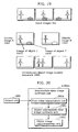
- FIG. 6 shows an example of the background b 303, the image f 1 304 of the object 1, and the image f 2 305 of the object 2, which have been obtained from input images 301.
- the background b 303, the image f 1 304 of the object 1, and the image f 2 305 of the object 2 are determined based on the respective Gaussian distribution parameters ( u f 2 ,v f 2 ),( u f 1 ,v f 1 ),( u b ,v b ), which are obtained for each pixel through the calculations from Equation 12 through Equation 17. More specifically, u f 2 ,u f 1 ,u b , which are the mean values of the Gaussian distributions, are used as the respective pixel values.
- an example of background b 303, an example of the image f 1 304 of the object 1, and an example of the image f 2 305 of the object 2 are synthesized from the plural input images. For this reason, an image sequence 601 of the object 1 and an image sequence 602 of the object 2 corresponding to the respective input images are synthesized using Tf . More specifically, the image sequence 601 and the image sequence 602 are synthesized by shifting the pixels of the synthesized image f 1 304 of the object 1 and image f 2 305 of the object 2, based on the motion T 1 306 of the object 1 and the motion T 2 307 of the object 2, respectively.
- the estimated shape m 1 310 of the object 1 and shape m 2 311 of the object 2 may be applied to images which have been synthesized using Tf .
- this application since this application is equivalent to masking the images using shape information, a noise removal effect can be expected.
- the output unit 105 by providing an image data division unit 701 in the output unit 105 as shown in the image processing device according to the first variation of the first comparative example of the present invention in FIG. 7 , it is possible for the output unit 105 to separately store or output (transfer) the background b 303, the image sequence 601 of the object 1, and the image sequence 602 of the object 2 to the outside.
- the output unit 105 separately transfers, in S801, one image of the background b 303, the image sequence 601 of the object 1, and the image sequence 602 of the object 2. This makes it possible to reduce background area information equivalent to that included in N-1 images, where N is the number of input images when using a fixed camera.
- the first embodiment is obtained by adding a function of determining the number of input images in the first comparative example.
- the number of input images required to appropriately extract hidden parameters depends greatly on image scenes, and thus it is not easy to determine the number of input images in advance. For example, it is not possible to extract an appropriate background image when plural input images include objects with little motion. For this reason, it is necessary to determine an appropriate number of images, depending on input images.
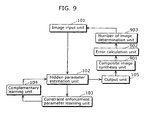
- FIG. 9 shows an outline of the processes performed in the first embodiment.
- the image processing device of the first embodiment is a device which has a function of determining an appropriate number of images depending on the input images, in addition to the functions of the image processing device of the first comparative example, and includes an image input unit 101, a hidden parameter estimation unit 102, a constraint enforcement parameter learning unit 103, a complementary learning unit 104, an output unit 105, a composite image synthesis unit 901, an error calculation unit 902, and a number of image determination unit 903. Since the constituent elements from the image input unit 101 to the output unit 105 are the same as those in the first comparative example, their descriptions will not be repeated.
- the hidden parameter estimation unit 102 synthesizes the image sequence 601 of the object 1 and the image sequence 602 of the object 2 according to the respective input images, based on the background b 303, the image f 1 304 of the object 1, and the image f 2 305 of the object 2, which are extracted as hidden parameters, as well as based on the motion T 1 306 of the object 1 and the motion T 2 307 of the object 2.
- the shape m 1 310 of the object 1 and the shape m 2 311 of the object 2 estimated by the hidden parameter estimation unit 102 may be applied to the synthesized images.
- the composite image synthesis unit 901 is a processing unit that accepts the background image and the respective object images, which are hidden parameters outputted from the hidden parameter estimation unit 102 via the output unit 105, and synthesizes a new image by superimposing the respective object images on the received background image.
- the composite image synthesis unit 901 synthesizes the same number of composite images as the number of input images, using the background b 303, the image sequence 601 of the object 1, and the image sequence 602 of the object 2.
- the error calculation unit 902 is a processing unit that calculates an error between each input image and each composite image synthesized by the composite image synthesis unit 901.
- the number of image determination unit 903 is a processing unit that causes the hidden parameter estimation unit 102 and the constraint enforcement parameter learning unit 103 to repeat their processes, using an increased number of input images, when an error calculated by the error calculation unit 902 is equal to or greater than a predetermined value.
- the number of image determination unit 903 compares the calculated error value with the predetermined value, and in the case where the calculated error value is greater than the predetermined value, sends, to the input image unit 101, a signal for causing the processes to be performed again with an increased number of images. Meanwhile, when the calculated error value is smaller than the predetermined value, the number of image determination unit 903 ends the process.
- a user input unit 1101 may be additionally provided, so that it is possible to inform the user of the fact that the number of input images is insufficient and to prompt the user to perform the processes again with an increased number of input images.
- FIG. 10 is a flowchart showing operations performed by the image processing device according to the first embodiment of the present invention. Referring to this flowchart, the following describes an example of determining the number of input images in the image processing method of the present invention.
- the composite image synthesis unit 901 synthesizes composite images s t in the following manner based on the background b 303, the image sequence 601 of the object 1, and the image sequence 602 of the object 2. As shown in FIG. 12 , the composite image synthesis unit 901 synthesizes a composite image sequence A1201 by superimposing the image sequence 601 of the object 1 onto the background b 303.
- the superimposition here refers to replacing the same pixels co-located in the background image and one image in the image sequence 601 of the object 1 by the corresponding pixel values of the image in the image sequence 601 of the object 1.
- the composite image synthesis unit 901 synthesizes a composite image sequence B1202 by superimposing the image sequence 602 of the object 2 onto the composite image sequence A1201.
- the superimposition here refers to replacing the same pixels co-located in one image in the composite image sequence A1201 and one image in the image sequence 602 of the object 2 by the corresponding pixel values of the image in the image sequence 602 of the object 2.
- the order in which superimposition is performed is determined by the definition of Equation 3. The above-description is applicable to the case where there is an increased number of objects and where camera motion is taken into account as shown in FIG. 4 .
- t denotes the number assigned to each input image and each composite image. It should be noted that it suffices if there is an appropriate correspondence between each input image and each composite image, and therefore they do not necessarily have to be placed in time series.
- M,N denotes the image size. The calculation of an error between each composite image and each input image may be done using another calculation method such as an S/N method.
- the number of image determination unit 903 compares the calculated error value Err with the predetermined value, and sends, in S1003, a signal for requiring the addition of input image(s) to the image input unit 101, when the error value Err exceeds the predetermined value. Then, the processes from S201 are performed again, using an increased number of input images.
- the user input unit 1101 may display, to the user, information indicating that the number of input images is insufficient.
- an intermediate time image synthesis method which uses the image processing method described in the first comparative example, is described for generating an intermediate time image by synthesizing an object image in an intermediate time between input images using the object image, the shapes of the object images and the motion of the object, which are extracted as hidden parameters, and by superimposing the object image in the intermediate time onto a background image in the time period.
- FIG. 13 shows a structure of the image processing device in the second comparative example.
- This image processing device is a device with a function for synthesizing an intermediate time image, in addition to the functions of the image processing device in the first comparative example, and includes the image input unit 101, the hidden parameter estimation unit 102, the constraint enforcement parameter learning unit 103, the complementary learning unit 104, the output unit 105 and an intermediate time image synthesis unit 1301.
- the image input unit 101 accepts plural images aligned in a time series. Note that the units from the hidden parameter estimation unit 102 to the complementary learning unit 104 are the same as the first comparative example and thus are not repeated.
- the intermediate time image synthesis unit 1301 is a processing unit which receives the background image, the object images, the shapes of the object images and the motion of the object images, synthesizing an object image at the intermediate time of the input images using the received background image, the object images, the shapes of the object images and the motion of the object images and synthesizing an intermediate time image by superimposing the object image at the intermediate time over the background image at that time.
- the intermediate time image synthesis unit 1301 uses a background b 303, an object image f 1 304, an image f 2 305 of the object 2, motion T 1 306 of the object 1 and motion T 2 307 of the object 2, which are extracted as hidden parameters in the hidden parameter estimation unit 102, and synthesizes an image that corresponds with the intermediate times of at least two input images by synthesizing an image of the object that corresponds with the intermediate time and superimposing it upon the background image.
- an intermediate time image based on the camera motion can be synthesized by treating the background b 303 as shown in FIG. 4 as an object with motion.
- the intermediate time image synthesis unit 1301 is configured with the object intermediate time image synthesis unit 1501 and the object image superimposition unit 1502, as shown in FIG. 15 .
- the object intermediate time image synthesis unit 1501 is a processing unit which receives the background image, the object images, the shapes of the object images and the motion of the object images and synthesizes an object image at the intermediate time of the input images using the received background image, the object images, the shapes of the object images and the motion of the object images.
- the object image superimposition unit 1502 is a processing unit which synthesizes an intermediate time image by superimposing the object image at the intermediate time synthesized by the object intermediate time image synthesis unit 1501 onto the background image at the intermediate time.
- the object intermediate time image synthesis unit 1501 synthesizes an object image at the intermediate time using the background b 303, the image f 1 304 of the object 1, the image f 2 305 of the object 2, the motion T 1 306 of the object 1 and the motion T 2 307 of the object 2, which are obtained in S206 as shown in FIG. 15 .
- a method for synthesizing intermediate time images f ⁇ 1 t + i and f ⁇ 1 t + j at a time resolution multiplied by n is described, as shown in FIG. 16 .
- object images which correspond to input images that are temporally consecutive are expressed as f 1 t , f 1 t + n and f 1 t + 2 ⁇ n .
- the object image f 1 t 1601 at the time t, the object image f 1 t + n 1602 at the time t+n and the object image f 1 t + 2 ⁇ n 1603 at the time t+2n can be synthesized by moving each pixel in the image f 1 304 of the object 1 using the motion T 1 306 of the object 1 as shown in FIG. 6 in the first comparative example.
- the intermediate time image f ⁇ 1 t + i 1604 of the object 1 can be synthesized with the same method used to synthesize the object image f 1 t 1601 and so on, by estimating motion T ⁇ 1 t + i for the intermediate time as in the following equation, and using the estimated motion T ⁇ 1 t + i for the object 1 and using the image f 1 304 of the object 1.
- T ⁇ 1 t + i n - i ⁇ T 1 t + i ⁇ T 1 t + n n 0 ⁇ i ⁇ n
- a 1 t T 1 t + 2 ⁇ n - 2 ⁇ T 1 t + n + T 1 t 2
- an intermediate time image is synthesized by superimposing the object image at the synthesized intermediate time onto the background image.
- an image at the same time as the input image can be synthesized by using the input image as is, or by performing a process similar to the synthesis process for the composite image in the composite image synthesis unit 901 of FIG. 9 .
- the intermediate time images f ⁇ 1 t + i 1604 and f ⁇ 1 t + j 1605 of the image object 1 at the synthesized intermediate time are superimposed onto the background b 303, in the same way as the composite image synthesis unit 901 for the intermediate time image f ⁇ 1 t + i 1604 of the object 1.
- an intermediate time image can be synthesized using the extracted background image, the object image, the shapes of the object images and the motion of the object.
- an image with a higher time resolution can be synthesized as well, using a captured image or a recorded video.
- a method for displaying the object image or the shapes of the object images, which are extracted as hidden parameters, in a monitor and the like, using the image processing method described in the first comparative example enables the user to select one of the displayed objects, erase the object image that the user has selected and synthesize an image wherein the erased object area is embedded within the background image.
- FIG. 17 shows an outline of the processes performed in the third comparative example.
- This image processing device includes the image input unit 101, the hidden parameter estimation unit 102, the constraint enforcement parameter learning unit 103, the complementary learning unit 104, the output unit 105, an object display unit 1701, a user input unit 1702 and an image synthesis unit 1703.
- the units from the image input unit 101 to the complementary learning unit 104 are the same as the first comparative example and are thus not repeated.
- the object display unit 1701 is a processing unit which displays the object image or the object image shape, which are extracted hidden parameters, in a monitor and the like, and in the present comparative example synthesizes at least one composite image using the background b 303, the image f 1 304 of the object 1 and the image f 2 305 of the object 2, which are extracted as hidden parameters in the hidden parameter estimation unit 102, and displays the image f 1 304 of the object 1 and the image f 2 305 of the object 2 in such a way as to be discernible from each other.
- the user input unit 1702 is a processing unit that acquires at least one selection from the user from among the objects displayed by the object display unit 1701, and in the present comparative example, the user selects an unnecessary object image from the object images displayed by the object display unit 1701.
- the image synthesis unit 1703 is a processing unit that deletes the object selected by the user by superimposing an object image which does not correspond to the object image or the shapes of the object images that the user has selected, and synthesizes an image in which the deleted object area is embedded in the background image; in the present comparative example, the object that the user has selected is erased by superimposing an object image that the user did not select on the background image and an image in which the erased object area is embedded in the background image is synthesized.
- At S1801 at least one composite image is synthesized using the background b 303, the image f 1 304 of the object 1 and the image f 2 305 of the object 2, which are extracted as hidden parameters by the hidden parameter estimation unit 102. More specifically, the image f 1 304 for the object 1 is superimposed on the background b 303.
- superimposition means to replace pixel values at the same position in the image with a pixel value of the image f 1 304 of the object 1.
- the image f 2 305 of the object 2 is superimposed on the superimposed image.
- the image f 1 304 of the object 1 and the image f 2 305 of the object 2 should be composed such that they overlap as little as possible.
- the user color codes the image 1903 for the object 1 and the image 1904 for the object 2 as shown in the display image A1901 and the display image B1902 in FIG. 19 such that they are easily distinguished, and displays them in a monitor or the like.
- the user selects an unnecessary object image from the composite image displayed in the monitor or the like.
- a specific object image alone may be selected using AV equipment such as a video camera, a TV and so on, or by turning a dial or the like on a remote controller and the like, by making selection possible via clicking with a mouse, or by direct selection via a touch panel equipped with a monitor or a video camera.
- the number of unnecessary objects is not limited. For example, by selecting all of the object images as unnecessary objects, the background image by itself may be obtained.
- the image synthesis unit 1703 erases the object selected by the user and synthesizes an image wherein the erased object area is embedded within the background image.
- an unnecessary object erasure sequence 1905 is shown, which is synthesized when the user selects the image 1904 for the object 2 as an unnecessary object. More specifically, an object image sequence using the object images that the user does not select is synthesized and this object image sequence is superimposed sequentially on the background b 303.
- the sequence of image synthesis is the same as that of the composite image synthesis unit 901 and thus the description is not repeated. Note that the superimposing sequence follows the definition in (Equation 3), however, processing is not performed for object images that the user does not select. Also, when the number of objects increases or the camera motion is included as in FIG. 4 , the overlapping can be handled in the same way.
- the background image and the respective object images which are extracted as hidden parameters, are images that have eliminated the effects of occlusions, in which pixel information in a part of the background or the object is missing due to an object covering an object.
- an image sequence which has eliminated the effect of this hiding can be synthesized.
- an image sequence can be synthesized in which the erased area is embedded in the background image.
- a method which can extract a background image and object images with comparatively little noise and synthesizes an intermediate time image when the pixel values for the extracted background image and each object image are inconstant and confidence is low in the first through third comparative examples, by interpolating the pixel values for the background image and each object image using a pixel value in an adjacent area.
- the synthesis of an intermediate time image is described as an example but the present invention may be applied to any of the examples from the first through the third comparative examples and the embodiments of the invention.
- FIG. 20 shows a structure of the image processing device in the fourth comparative example.
- This image processing device is a device that includes a function of synthesizing the intermediate time image using pixel interpolation, in addition to the functions of the image processing device in the first comparative example, and includes the image input unit 101, the hidden parameter estimation unit 102, the constraint enforcement parameter learning unit 103, the complementary learning unit 104, the output unit 105, and the intermediate time image synthesis unit 1301a.
- the intermediate time image synthesis unit 1301 is composed of a pixel value interpolation unit 2001, an object intermediate time image synthesis unit 1501 and an object image superimposition unit 1502.
- the pixel value interpolation unit 2001 is a processing unit which receives the background image and each object image, which are hidden parameters outputted from the output unit 105, and when the reliability of the pixel value for the received background image and each object image is low, interpolates the pixel value using an adjacent area pixel value; in the present comparative example, the pixel value interpolation unit 2001 interpolates the pixel value with a low reliability using an adjacent pixel value based on the precision of Gaussian distribution parameters for the background image and the object images extracted in the hidden parameter estimation unit 102.
- an intermediate time image is synthesized using a pixel value interpolated by the pixel value interpolation unit instead of the pixel value of the image extracted by the hidden parameter estimation unit 102.
- the pixel value interpolation unit 2001 determines the reliability of the pixel value using Gaussian distributions parameters ( u f 2 ,v f 2 ),( u f 1 , v f 1 ),( u b ,v b ) for the background b 303, the image f 1 304 of object 1 and the image f 2 305 of the object 2, which are obtained by calculating the equations from (equation 12) to (equation 17) in the hidden parameter estimation unit 102 at S206.
- v f 2 , v f 1 , v b is used as a determination basis for the reliability of the pixel value.
- v f 2 , v f 1 , v b is a precision that is a reciprocal distribution and is obtained for every pixel. Subsequently, the reliability of each pixel is assessed according to the relationship between v j 2 ,v f 1 ,v b and a pre-set threshold value TH_P.
- a pixel with a smaller precision than the threshold value TH_P is interpolated using an adjacent pixel value and the precision.
- u f ⁇ 2 _ new ⁇ j v f ⁇ 2 _ j u f ⁇ 2 _ j ⁇ j v f ⁇ 2 _ j
- j stands for 4 or 8 pixels adjacent the pixel to be interpolated.
- u f 1 _new and u b_new can be calculated in the same way and so their explanation is not repeated.
- the interpolation method for the pixel value is not limited to (Equation 50) and may be any method which uses information related to the reliability of the pixel value.
- a composite image is synthesized using images that are respectively interpolated instead of the background b 303, the image f 1 304 of object 1 and the image f 2 305 of the object 2. Synthesizing the composite image is the same in S1001 in the first embodiment of the invention, S1402 in the second comparative example, S1801 in the third comparative example and so on, thus the description is not repeated.
- a method for defining the parameters in a point spread function, which expresses the blurriness of the image as one of the hidden parameters in the first through fourth comparative examples and the embodiments of the invention, and for extracting a background image and each object image with the quality of the reconstructed input image.
- the image processing device in the present comparative example is a device which has a function of extracting a background image and object images which have a revised image quality compared to the input images using a point spread function, in addition to the functions of the image processing device in the first through fourth comparative examples and the embodiments of the invention, and includes a hidden parameter estimation unit 102a in addition to the hidden parameter estimation unit 102 which is included in the first through fourth comparative examples and the embodiments of the invention.
- the hidden parameter estimation unit 102a is described below since only the hidden parameter estimation unit 102a differs from the first through the fourth comparative examples and the embodiments of the invention.
- the hidden parameter estimation unit 102a has a function of holding a point spread function parameter which expresses the deterioration process of an image as a hidden parameter in addition to the functions of the hidden parameter estimation unit 102 in the first through fourth comparative examples and the embodiments of the invention, and synthesizing a background image and object images that have enhanced quality greater than the input images by estimating the inverse function of the function.
- FIG. 22 The configuration in FIG. 22 is used in place of FIG. 3 .
- the present invention is configured with a point spread function ⁇ b 2201 for the background b 303, a point spread function ⁇ f 1 2202 for the image f 1 304 of the object 1, and a point spread function ⁇ f2 2203 for the image f 2 305 of the object 2.
- the point spread function for the background b 303 is defined with a two dimensional Gaussian distribution as in the following equation.
- ⁇ b x b y b 1 2 ⁇ ⁇ ⁇ ⁇ b ⁇ exp - x b - s x_b ⁇ ⁇ b - 1 ⁇ y b - s y_b
- (x b ,y b ) are each pixel positions in a background image and ( s x_b ,s y_b ) are average pixels in a Gaussian distribution.
- b ( x b ,y b ) indicates a deteriorated image
- b new ( x b ,y b ) indicates a high-quality image before deterioration
- ⁇ b ( x b ,y b ) indicates a point spread function for making b new ( x b ,y b ) deteriorate.
- the image deterioration equation in Equation 52 can be applied to image quality enhancement.
- the background b 303 can obtain an image with blur corrected as the background b new .
- a point spread function for the image f 1 304 of the object 1 and a point spread function for the image f 2 305 of the object 2 can be defined in the same way.
- Equation 1 and (Equation 2) can be rewritten using the point spread functions ⁇ b , ⁇ f1 , ⁇ f2 in the following manner.
- P x f b ⁇ ⁇ T m P x
- b , f , m , T , ⁇ , ⁇ N ⁇ x k
- T 2 ⁇ ⁇ f ⁇ 2 ⁇ f 2 k , ⁇ f ⁇ 2 - 1 ⁇ m 2 ⁇ N ⁇ x k
- T 1 ⁇ ⁇ f ⁇ 1 ⁇ f 1 k , ⁇ f ⁇ 1 - 1 ⁇ m 1 ⁇ N ⁇ x k
- each Gaussian distribution parameter to be sought is ( U new_b ,v new_ b ),( u new _f 2 , v new_f 2 ),( u new_f 1 , v new_f 1 ).
- u new_b t ⁇ v new_b t u new_b ⁇ v new_b + ⁇ ⁇ b ⁇ ⁇ b - 1 ⁇ 1 - m 1 - m 2 ⁇ x >
- v new_b t v new_b - ⁇ ⁇ b ⁇ ⁇ b - 1 * 1 - m 1 - m 2 >
- ⁇ x_b is an x directional element of ⁇ b in (Equation 51). Also, y directional elements are calculated in the same way as (Equation 59) and (Equation 60).
- the point spread function parameter ⁇ f1 2202 for the image f 1 304 of the object 1 and the point spread function parameter ⁇ f 2 2203 for the image f 1 304 of the object 1 can be found in the same way.
- the hidden parameter estimation unit 102 can obtain an image in which the effects of blurring are repaired, especially related to optical blur.
- the point spread function for the image f 1 304 of the object 1, and the point spread function for the image f 2 305 of the object 2 may be defined in the same way.
- the time resolution can be increased more than the input image sequence and the quality of the image can be enhanced.
- AV equipment such as a video camera or a TV
- an image with a higher time resolution and enhanced image quality can be synthesized from a captured image or a recorded moving image.
- the image processing device in the present comparative example includes a constraint enforcement parameter learning unit 103a instead of the constraint enforcement parameter learning unit 103 included in the image processing device in the first comparative example.
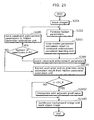
- the constraint enforcement parameter learning unit 103a is a processing unit which selects a pixel adjacent the pixel to become a pair, determines whether each pixel belongs to the background image or each object image area, and applies respective, differing constraints to the hidden parameter when the respective pixels belong to different objects and when the respective pixels belong to the same object. Below, the operations of the constraint enforcement parameter learning unit are explained using FIG. 23 .
- the hidden parameter estimation unit 102 transmits the hidden parameter estimation result estimated in S202, as shown in FIG. 23 , to the constraint enforcement parameter learning unit 103a.
- a shape m 1 310 of the object 1 and a shape m 2 311 of the object 2, which are hidden parameters, are used for the learning of the constraint enforcement parameter.
- the learning for the constraint enforcement parameter is not limited to a shape of an object and may be a hidden parameter as written above.
- the estimation result for the hidden parameter which is transmitted in S203, is made into a training signal and the constraint enforcement parameter is learned.
- constraint enforcement parameters related to the shape m 1 310 of the object 1 and the shape m 2 311 of the object 2 are learned, with the hidden parameter estimation result for the shape m 1 310 and the shape m 2 311 of the object 2 made into a training signal Q ( m i )501.
- the constraint enforcement parameter learning unit 103 is described using FIG. 23 .
- the constraint enforcement parameter learning unit is configured with the pixel position information L2301, the inter-pixel information for two pixels d ij 2302, an object size parameter w L 2303 and a pay-wise parameter w d 2304.
- the pixel position information L2301 holds position information for the pixels obtained from the input image.
- the inter-pixel information for two pixels d ij 2302 holds information related to luminance information between two pixels in the input image.
- constraint enforcement parameters that express the size of the object based on the pixel position information L2301 are learned.
- a pair-wise parameter w d 2304 assesses whether the respective pixels in the two pixel information d ij 2302 belong to the background image area or one of the object image areas. Different constraint enforcement parameters are learned when the respective pixels belong to different objects and when the respective pixels belong to the same object.
- the constraint enforcement parameter learning unit 103a learns the constraint enforcement parameter by learning the object size parameter w L 2303 and the pair-wise parameter w d 2304. As mentioned in the first comparative example, pixel motion information can of course also be used.
- a constraint enforcement parameter using the relationship between the pixel position information L2301 and the object size parameter w L 2303 is expressed as in the following equation.
- p c m 1
- L exp - w L ⁇ 1 ⁇ L - w L ⁇ 2 2
- p c m 2
- L exp - w L ⁇ 3 ⁇ L - w L ⁇ 4 2
- L is the position of each pixel. Finding the object size parameter ( w L 1 ,...w L 4 ) 2303 means learning the constraint enforcement parameter.
- the constraint enforcement parameter is also learned.
- the constraint enforcement parameters expressed as in the equations from (Equation 61) to (Equation 63) can be thought of as a Gaussian distribution with an average value and precision as parameters.
- the constraint enforcement parameters can be learned via the update equations for Gaussian distribution, (Equation 12) through (Equation 17), as well as similar update equations.
- x ) 502 is transmitted to the hidden parameter estimation unit 102 as shown in FIG. 23 .
- processing is performed as in S202.
- x ) functions as a constraint for finding the shape m 1 310 of the object 1 and the shape m 2 311 of the object 2. More specifically, processing is performed by adding the constraint enforcement parameter p c ( m i
- the hidden parameter estimation unit 102 can estimate a hidden parameter while avoiding a local minimum.
- learning the constraint enforcement parameter is described for the shape m 1 310 of the object 1 and the shape m 2 311 of the object 2, however it is also possible to add the constraint perimeter in the same way to another hidden parameter as in (Equation 43) and (Equation 44).
- the hidden parameter estimation unit 102 even when a constraint enforcement parameter is added to only the shape m 1 310 of the object 1 and the shape m 2 311 of the object 2, the efficacy for avoiding a local minimum can be applied to the other hidden parameters in order to optimize all hidden parameters simultaneously.
- a hidden parameter which has avoided a local minimum can be estimated without directly adding constraint enforcement parameters to the background b 303, the image f 1 304 of the object 1, the image f 2 305 of the object 2, the motion T 1 306 of the object 1 and the motion T 2 307 of the object 2, which are hidden parameters to be found.
- the present invention can be used as an image processing device that simultaneously extracts a background image and an object image from among plural images, and in particular can be used as an image processing device for simultaneously extracting a background image, at least two object images, the shape of each object image and the motion of each object image from among plural images, while avoiding a local minimum.
- the present invention can also be used as an image processing device and so on packaged inside AV equipment such as a motion analysis device, a surveillance device, a video camera or a TV.
Landscapes
- Engineering & Computer Science (AREA)
- Physics & Mathematics (AREA)
- Computer Vision & Pattern Recognition (AREA)
- Theoretical Computer Science (AREA)
- Multimedia (AREA)
- General Physics & Mathematics (AREA)
- Psychiatry (AREA)
- Human Computer Interaction (AREA)
- Social Psychology (AREA)
- Health & Medical Sciences (AREA)
- General Health & Medical Sciences (AREA)
- Image Analysis (AREA)
- Image Processing (AREA)
- Studio Devices (AREA)
- Separation By Low-Temperature Treatments (AREA)
- Ultra Sonic Daignosis Equipment (AREA)
- Magnetic Resonance Imaging Apparatus (AREA)
- Medicines Containing Material From Animals Or Micro-Organisms (AREA)
Claims (3)
- Procédé de traitement d'image consistant à extraire simultanément, à partir d'images multiples, un fond d'image (303), au moins deux images-objets (304, 305), une forme (310, 311) de chaque image-objet et le mouvement (306, 307) de chaque image-objet, chacun de ces éléments étant défini comme des paramètres cachés, ledit procédé de traitement d'image comprenant :une étape d'introduction d'image (S201) consistant à accepter l'introduction d'images multiples disposées en série chronologique ;une étape d'estimation des paramètres cachés (S202) consistant à estimer les paramètres cachés en se basant sur les images multiples et sur un paramètre d'application de contrainte (502), qui indique un état d'au moins un des paramètres cachés, en utilisant un procédé d'apprentissage itératif ;une étape d'apprentissage de paramètre d'application de contrainte (S204) consistant à apprendre un paramètre d'application de contrainte relatif à au moins un paramètre caché en utilisant comme signal de formation (501) un résultat d'estimation du au moins un paramètre caché obtenu lors de ladite étape d'estimation des paramètres cachés (S202) ;une étape d'apprentissage complémentaire (S205) consistant à causer l'itération de l'estimation du paramètre cachée et de l'apprentissage du paramètre d'application de contrainte, l'estimation des paramètres cachés étant exécutée lors de ladite étape d'estimation des paramètres cachés (S202), qui utilise un résultat d'apprentissage obtenu lors ladite étape d'apprentissage du paramètre d'application de contrainte (S204), et l'apprentissage du paramètre d'application de contrainte étant exécuté lors de ladite étape d'apprentissage du paramètre d'application de contrainte (S204), qui utilise le résultat d'estimation des paramètres cachés obtenu lors de ladite étape d'estimation des paramètres cachés (S202)une étape de sortie consistant à produire les paramètres cachés estimés lors de ladite étape d'estimation des paramètres cachés après que l'apprentissage itératif a été exécuté lors de ladite étape d'apprentissage complémentaire ;caractérisé par :une étape de synthèse d'image composite (S206, S1001) consistant à recevoir le fond d'image et chaque image-objet, qui sont des paramètres cachés produits lors de ladite étape de sortie, et à synthétiser nouvellement une pluralité d'images en superposant chaque image-objet sur le fond d'image reçu ;une étape de calcul d'erreur (S1002) consistant à calculer une erreur en valeurs de pixels entre les images synthétisées lors de ladite étape de synthèse d'image composite et les images introduites ; etune étape de jugement du nombre d'images consistant à augmenter (S1003) le nombre d'images introduites lorsque l'erreur calculée lors de ladite étape de calcul d'erreur (S1002) est égale ou supérieure à la valeur spécifiée, et à causer la nouvelle exécution itérative du traitement de ladite étape d'estimation des paramètres cachés (S202) et de ladite étape d'apprentissage du paramètre d'application de contrainte (S204) en utilisant le nombre augmenté d'images introduites ou en affichant à un utilisateur que le nombre d'images introduites est insuffisant.
- Dispositif de traitement d'image qui extrait simultanément, à partir d'images multiples, un fond d'image (303), au moins deux images-objets (304, 305), une forme (310, 311) de chaque image-objet et le mouvement (306, 307) de chaque image-objet, chacun de ces éléments étant défini comme des paramètres cachés, ledit dispositif de traitement d'image comprenant :une unité d'introduction d'image (101) pouvant être utilisée pour accepter l'introduction de plusieurs images disposées en série chronologique ;une unité d'estimation des paramètres cachés (102) pouvant être utilisée pour estimer les paramètres cachés en se basant sur les images multiples et sur un paramètre d'application de contrainte (502), qui indique un état d'au moins un des paramètres cachés, en utilisant un procédé d'apprentissage itératif ;une unité d'apprentissage de paramètre d'application de contrainte (103) pouvant être utilisée pour apprendre un paramètre d'application de contrainte relatif à au moins un paramètre caché en utilisant comme signal de formation un résultat d'estimation du au moins un paramètre caché donné par ladite unité d'estimation des paramètres cachés ;une unité d'apprentissage complémentaire (104) pouvant être utilisée pour causer l'itération de l'estimation du paramètre caché et de l'apprentissage du paramètre d'application de contrainte, l'estimation des paramètres cachés étant exécutée par ladite unité d'estimation des paramètres cachés (102), qui utilise un résultat d'apprentissage donné par ladite unité d'apprentissage du paramètre d'application de contrainte (103), et l'apprentissage du paramètre d'application de contrainte étant exécuté par ladite unité d'apprentissage du paramètre d'application de contrainte (103), qui utilise le résultat d'estimation des paramètres cachés donné par ladite unité d'estimation des paramètres cachés (102)une unité de sortie (105) pouvant être utilisée pour produire les paramètres cachés estimés par ladite unité d'estimation des paramètres cachés (102) après que l'apprentissage itératif a été exécuté par ladite unité d'apprentissage complémentaire (104) ;caractérisé par :une unité de synthèse d'image composite (901) pouvant être utilisée pour recevoir le fond d'image et chaque image-objet, qui sont des paramètres cachés produits par ladite unité de sortie (105), et pour synthétiser nouvellement une pluralité d'images en superposant chaque image-objet sur le fond d'image reçu ;une unité de calcul d'erreur (902) pouvant être utilisée pour calculer une erreur en valeurs de pixels entre les images synthétisées par ladite unité de synthèse d'image composite et les images introduites ; etune unité de jugement du nombre d'images (903) pouvant être utilisée pour augmenter le nombre d'images introduites lorsque l'erreur calculée par ladite unité de calcul d'erreur (902) est égale ou supérieure à la valeur spécifiée, et pour causer la nouvelle exécution itérative du traitement de ladite unité d'estimation des paramètres cachés (102) et de ladite unité d'apprentissage du paramètre d'application de contrainte (103) en utilisant le nombre augmenté d'images introduites ou en affichant à un utilisateur que le nombre d'images introduites est insuffisant.
- Programme de traitement d'image pour extraire simultanément, à partir d'images multiples (301), un fond d'image (303), au moins deux images-objets (304, 305), une forme (310, 311) de chaque image-objet et le mouvement (306, 307) de chaque image-objet, chacun de ces éléments étant défini comme des paramètres cachés, ledit programme de traitement d'image faisant exécuter par un ordinateur :une étape d'introduction d'image (S201) consistant à accepter l'introduction d'images multiples disposées en série chronologique ;une étape d'estimation des paramètres cachés (S202) consistant à estimer les paramètres cachés en se basant sur la pluralité d'images et sur un paramètre d'application de contrainte (502), qui indique un état d'au moins un des paramètres cachés, en utilisant un procédé d'apprentissage itératif ;une étape d'apprentissage de paramètre d'application de contrainte (S204) consistant à apprendre un paramètre d'application de contrainte relatif à au moins un paramètre caché en utilisant comme signal de formation un résultat d'estimation du au moins un paramètre caché obtenu lors de ladite étape d'estimation des paramètres cachés (S202) ;une étape d'apprentissage complémentaire (S205) consistant à causer l'itération de l'estimation des paramètres cachés et de l'apprentissage du paramètre d'application de contrainte, l'estimation des paramètres cachés étant exécutée lors de ladite étape d'estimation des paramètres cachés (S202), qui utilise un résultat d'apprentissage obtenu lors de ladite étape d'apprentissage du paramètre d'application de contrainte (S204), et l'apprentissage du paramètre d'application de contrainte étant exécuté lors de ladite étape d'apprentissage du paramètre d'application de contrainte (S204), qui utilise le résultat d'estimation des paramètres cachés obtenu lors ladite étape d'estimation des paramètres cachés (S202) ; etune étape de sortie consistant à produire les paramètres cachés estimés lors de ladite étape d'estimation des paramètres cachés (S202) après que l'apprentissage itératif a été exécuté lors de ladite étape d'apprentissage complémentaire ;caractérisé par :une étape de synthèse d'image composite (S206, S1001) consistant à recevoir le fond d'image et chaque image-objet, qui sont des paramètres cachés produits lors de ladite étape de sortie, et à synthétiser nouvellement une pluralité d'images en superposant chaque image-objet sur le fond d'image reçu ;une étape de calcul d'erreur (S1002) consistant à calculer une erreur en valeurs de pixels entre les images synthétisées lors de ladite étape de synthèse d'image composite et les images introduites ; etune étape de jugement du nombre d'images consistant à augmen ter (S1003) le nombre d'images introduites lorsque l'erreur calculée lors de ladite étape de calcul d'erreur (S1002) est égale ou supérieure à la valeur spécifiée, et à causer la nouvelle exécution itérative du traitement de ladite étape d'estimation des paramètres cachés (S202) et de ladite étape d'apprentissage du paramètre d'application de contrainte (S204) en utilisant le nombre augmenté d'images introduites ou en affichant à un utilisateur que le nombre d'images introduites est insuffisant.
Priority Applications (1)
| Application Number | Priority Date | Filing Date | Title |
|---|---|---|---|
| DE602006014602T DE602006014602D1 (de) | 2006-12-01 | 2006-12-01 | Iterative Bewegungs-Segmentierung |
Applications Claiming Priority (2)
| Application Number | Priority Date | Filing Date | Title |
|---|---|---|---|
| EP06820390A EP1946269B1 (fr) | 2006-12-01 | 2006-12-01 | Segmentation de mouvement itérative |
| PCT/GB2006/004502 WO2008065319A1 (fr) | 2006-12-01 | 2006-12-01 | Segmentation de mouvement itérative |
Related Parent Applications (2)
| Application Number | Title | Priority Date | Filing Date |
|---|---|---|---|
| EP06820390A Division EP1946269B1 (fr) | 2006-12-01 | 2006-12-01 | Segmentation de mouvement itérative |
| EP06820390.0 Division | 2006-12-01 |
Publications (2)
| Publication Number | Publication Date |
|---|---|
| EP2061009A1 EP2061009A1 (fr) | 2009-05-20 |
| EP2061009B1 true EP2061009B1 (fr) | 2010-05-26 |
Family
ID=38122004
Family Applications (2)
| Application Number | Title | Priority Date | Filing Date |
|---|---|---|---|
| EP06820390A Not-in-force EP1946269B1 (fr) | 2006-12-01 | 2006-12-01 | Segmentation de mouvement itérative |
| EP09152112A Not-in-force EP2061009B1 (fr) | 2006-12-01 | 2006-12-01 | Segmentation de mouvement itérative |
Family Applications Before (1)
| Application Number | Title | Priority Date | Filing Date |
|---|---|---|---|
| EP06820390A Not-in-force EP1946269B1 (fr) | 2006-12-01 | 2006-12-01 | Segmentation de mouvement itérative |
Country Status (7)
| Country | Link |
|---|---|
| US (1) | US7970205B2 (fr) |
| EP (2) | EP1946269B1 (fr) |
| JP (1) | JP4643741B2 (fr) |
| CN (1) | CN101292264B (fr) |
| AT (2) | ATE469407T1 (fr) |
| DE (2) | DE602006014602D1 (fr) |
| WO (1) | WO2008065319A1 (fr) |
Families Citing this family (10)
| Publication number | Priority date | Publication date | Assignee | Title |
|---|---|---|---|---|
| US8254626B2 (en) * | 2006-12-22 | 2012-08-28 | Fujifilm Corporation | Output apparatus, output method and program for outputting a moving image including a synthesized image by superimposing images |
| CN102096936B (zh) * | 2009-12-14 | 2013-07-24 | 北京中星微电子有限公司 | 一种图像生成方法及装置 |
| JP2011176542A (ja) * | 2010-02-24 | 2011-09-08 | Nikon Corp | カメラおよび画像合成プログラム |
| US20120050316A1 (en) * | 2010-08-31 | 2012-03-01 | Nokia Corporation | Methods and apparatuses for enhancing wallpaper display |
| US10115431B2 (en) | 2013-03-26 | 2018-10-30 | Sony Corporation | Image processing device and image processing method |
| WO2014174438A1 (fr) * | 2013-04-21 | 2014-10-30 | Nova Measuring Instruments Ltd. | Procédé et système permettant d'améliorer des mesures optiques sur de petites cibles |
| MA41117A (fr) | 2014-12-05 | 2017-10-10 | Myfiziq Ltd | Imagerie d'un corps |
| EP3602398B1 (fr) * | 2017-06-05 | 2022-04-13 | Siemens Aktiengesellschaft | Procédé et appareil d'analyse d'image |
| US11429814B2 (en) * | 2018-04-12 | 2022-08-30 | Nec Corporation | Learning image generation apparatus, learning image generation method, and non-transitory storage medium |
| DE102019132514B3 (de) * | 2019-11-29 | 2021-02-04 | Carl Zeiss Meditec Ag | Optisches Beobachtungsgerät sowie Verfahren und Datenverarbeitungssystem zum Ermitteln von Informationen zum Unterscheiden zwischen Gewebeflüssigkeitszellen und Gewebezellen |
Family Cites Families (5)
| Publication number | Priority date | Publication date | Assignee | Title |
|---|---|---|---|---|
| JP3213105B2 (ja) | 1993-02-23 | 2001-10-02 | 日本電信電話株式会社 | 映像の構図自動決定処理方法 |
| US6826292B1 (en) * | 2000-06-23 | 2004-11-30 | Sarnoff Corporation | Method and apparatus for tracking moving objects in a sequence of two-dimensional images using a dynamic layered representation |
| JP2002352248A (ja) | 2001-05-25 | 2002-12-06 | Nhk Engineering Services Inc | 映像オブジェクト抽出支援装置 |
| JP2005276149A (ja) | 2004-03-24 | 2005-10-06 | Win Animate:Kk | 移動ベクトル検出装置,移動ベクトル検出プログラム,中間画像作成装置および中間画像作成プログラム |
| JP4403937B2 (ja) | 2004-09-29 | 2010-01-27 | カシオ計算機株式会社 | カメラ装置、情報処理装置、被写体識別方法 |
-
2006
- 2006-12-01 WO PCT/GB2006/004502 patent/WO2008065319A1/fr not_active Ceased
- 2006-12-01 EP EP06820390A patent/EP1946269B1/fr not_active Not-in-force
- 2006-12-01 US US11/994,748 patent/US7970205B2/en active Active
- 2006-12-01 AT AT09152112T patent/ATE469407T1/de not_active IP Right Cessation
- 2006-12-01 CN CN2006800240013A patent/CN101292264B/zh not_active Expired - Fee Related
- 2006-12-01 JP JP2009538761A patent/JP4643741B2/ja not_active Expired - Fee Related
- 2006-12-01 AT AT06820390T patent/ATE472143T1/de not_active IP Right Cessation
- 2006-12-01 DE DE602006014602T patent/DE602006014602D1/de active Active
- 2006-12-01 EP EP09152112A patent/EP2061009B1/fr not_active Not-in-force
- 2006-12-01 DE DE602006015085T patent/DE602006015085D1/de active Active
Also Published As
| Publication number | Publication date |
|---|---|
| ATE472143T1 (de) | 2010-07-15 |
| DE602006015085D1 (de) | 2010-08-05 |
| DE602006014602D1 (de) | 2010-07-08 |
| US7970205B2 (en) | 2011-06-28 |
| CN101292264B (zh) | 2013-06-12 |
| CN101292264A (zh) | 2008-10-22 |
| EP2061009A1 (fr) | 2009-05-20 |
| US20100128926A1 (en) | 2010-05-27 |
| JP4643741B2 (ja) | 2011-03-02 |
| EP1946269B1 (fr) | 2010-06-23 |
| JP2010511241A (ja) | 2010-04-08 |
| ATE469407T1 (de) | 2010-06-15 |
| WO2008065319A1 (fr) | 2008-06-05 |
| EP1946269A1 (fr) | 2008-07-23 |
Similar Documents
| Publication | Publication Date | Title |
|---|---|---|
| Dosovitskiy et al. | Flownet: Learning optical flow with convolutional networks | |
| KR100677913B1 (ko) | 다중 센서 비디오 신호의 융합에 의한 이동 객체 추적 장치 | |
| JP4181473B2 (ja) | 映像オブジェクト軌跡合成装置、その方法及びそのプログラム | |
| Badenas et al. | Motion-based segmentation and region tracking in image sequences | |
| EP3054686B1 (fr) | Estimation de mouvement hiérarchique et segmentation en présence de plus d'un objet mobile dans une fenêtre de recherche | |
| WO2009112790A1 (fr) | Procédé de traitement d’image et appareil de traitement d’image | |
| WO2001004055A2 (fr) | Procede et appareil d'estimation par correlation d'une structure scenique et du mouvement de l'observateur a partir des images d'une scene | |
| KR101548639B1 (ko) | 감시 카메라 시스템의 객체 추적장치 및 그 방법 | |
| Ali et al. | Multiple object tracking with partial occlusion handling using salient feature points | |
| EP2061009B1 (fr) | Segmentation de mouvement itérative | |
| CN102622764A (zh) | 一种基于移动相机平台的目标跟踪方法 | |
| CN117274636A (zh) | 一种基于孪生神经网络的遥感卫星视频目标跟踪方法 | |
| CN117392176A (zh) | 用于视频监控的行人追踪方法及系统、计算机可读介质 | |
| EP3115967A1 (fr) | Procédé de commande de suivi à l'aide d'un modèle de couleur, appareil correspondant et dispositif de stockage de programme non transitoire | |
| JP2010511241A5 (fr) | ||
| Kahl et al. | Novelty detection in image sequences with dynamic background | |
| Shahbaz et al. | Probabilistic foreground detector with camouflage detection for sterile zone monitoring | |
| JP4637275B2 (ja) | 画像処理方法及び画像処理装置 | |
| Mattioli et al. | Maximum likelihood speed estimation of moving objects in video signals | |
| Shafiee et al. | Model-based tracking: Temporal conditional random fields | |
| Rodrı́guez et al. | A multiresolution spatiotemporal motion segmentation technique for video sequences based on pyramidal structures | |
| Sreegeethi et al. | Online Video Stabilization using Mesh Flow with Minimum Latency | |
| Pande et al. | Implementation and analysis of various background subtraction techniques for IR target detection using different filters | |
| Biresaw et al. | Online failure detection and correction for Bayesian sparse feature-based object tracking | |
| Vamsi et al. | Image splicing detection using HMRF superpixel segmentation |
Legal Events
| Date | Code | Title | Description |
|---|---|---|---|
| PUAI | Public reference made under article 153(3) epc to a published international application that has entered the european phase |
Free format text: ORIGINAL CODE: 0009012 |
|
| AC | Divisional application: reference to earlier application |
Ref document number: 1946269 Country of ref document: EP Kind code of ref document: P |
|
| AK | Designated contracting states |
Kind code of ref document: A1 Designated state(s): AT BE BG CH CY CZ DE DK EE ES FI FR GB GR HU IE IS IT LI LT LU LV MC NL PL PT RO SE SI SK TR |
|
| RIN1 | Information on inventor provided before grant (corrected) |
Inventor name: CIPOLLA, ROBERTO Inventor name: THAYANANTHAN, ARASANATHAN Inventor name: IWASAKI, MASAHIRO |
|
| RIN1 | Information on inventor provided before grant (corrected) |
Inventor name: THAYANANTHAN, ARASANATHAN Inventor name: IWASAKI, MASAHIRO Inventor name: CIPOLLA, ROBERTO |
|
| GRAJ | Information related to disapproval of communication of intention to grant by the applicant or resumption of examination proceedings by the epo deleted |
Free format text: ORIGINAL CODE: EPIDOSDIGR1 |
|
| GRAP | Despatch of communication of intention to grant a patent |
Free format text: ORIGINAL CODE: EPIDOSNIGR1 |
|
| 17P | Request for examination filed |
Effective date: 20091109 |
|
| RIN1 | Information on inventor provided before grant (corrected) |
Inventor name: IWASAKI, MASAHIRO Inventor name: THAYANANTHAN, ARASANATHAN Inventor name: CIPOLLA, ROBERTO |
|
| AKX | Designation fees paid |
Designated state(s): AT BE BG CH CY CZ DE DK EE ES FI FR GB GR HU IE IS IT LI LT LU LV MC NL PL PT RO SE SI SK TR |
|
| GRAS | Grant fee paid |
Free format text: ORIGINAL CODE: EPIDOSNIGR3 |
|
| GRAA | (expected) grant |
Free format text: ORIGINAL CODE: 0009210 |
|
| AC | Divisional application: reference to earlier application |
Ref document number: 1946269 Country of ref document: EP Kind code of ref document: P |
|
| AK | Designated contracting states |
Kind code of ref document: B1 Designated state(s): AT BE BG CH CY CZ DE DK EE ES FI FR GB GR HU IE IS IT LI LT LU LV MC NL PL PT RO SE SI SK TR |
|
| REG | Reference to a national code |
Ref country code: GB Ref legal event code: FG4D |
|
| REG | Reference to a national code |
Ref country code: CH Ref legal event code: EP |
|
| REG | Reference to a national code |
Ref country code: IE Ref legal event code: FG4D |
|
| REF | Corresponds to: |
Ref document number: 602006014602 Country of ref document: DE Date of ref document: 20100708 Kind code of ref document: P |
|
| REG | Reference to a national code |
Ref country code: NL Ref legal event code: VDEP Effective date: 20100526 |
|
| LTIE | Lt: invalidation of european patent or patent extension |
Effective date: 20100526 |
|
| PG25 | Lapsed in a contracting state [announced via postgrant information from national office to epo] |
Ref country code: SE Free format text: LAPSE BECAUSE OF FAILURE TO SUBMIT A TRANSLATION OF THE DESCRIPTION OR TO PAY THE FEE WITHIN THE PRESCRIBED TIME-LIMIT Effective date: 20100526 Ref country code: LT Free format text: LAPSE BECAUSE OF FAILURE TO SUBMIT A TRANSLATION OF THE DESCRIPTION OR TO PAY THE FEE WITHIN THE PRESCRIBED TIME-LIMIT Effective date: 20100526 |
|
| PG25 | Lapsed in a contracting state [announced via postgrant information from national office to epo] |
Ref country code: SI Free format text: LAPSE BECAUSE OF FAILURE TO SUBMIT A TRANSLATION OF THE DESCRIPTION OR TO PAY THE FEE WITHIN THE PRESCRIBED TIME-LIMIT Effective date: 20100526 Ref country code: LV Free format text: LAPSE BECAUSE OF FAILURE TO SUBMIT A TRANSLATION OF THE DESCRIPTION OR TO PAY THE FEE WITHIN THE PRESCRIBED TIME-LIMIT Effective date: 20100526 Ref country code: IS Free format text: LAPSE BECAUSE OF FAILURE TO SUBMIT A TRANSLATION OF THE DESCRIPTION OR TO PAY THE FEE WITHIN THE PRESCRIBED TIME-LIMIT Effective date: 20100926 Ref country code: FI Free format text: LAPSE BECAUSE OF FAILURE TO SUBMIT A TRANSLATION OF THE DESCRIPTION OR TO PAY THE FEE WITHIN THE PRESCRIBED TIME-LIMIT Effective date: 20100526 Ref country code: AT Free format text: LAPSE BECAUSE OF FAILURE TO SUBMIT A TRANSLATION OF THE DESCRIPTION OR TO PAY THE FEE WITHIN THE PRESCRIBED TIME-LIMIT Effective date: 20100526 |
|
| PG25 | Lapsed in a contracting state [announced via postgrant information from national office to epo] |
Ref country code: PL Free format text: LAPSE BECAUSE OF FAILURE TO SUBMIT A TRANSLATION OF THE DESCRIPTION OR TO PAY THE FEE WITHIN THE PRESCRIBED TIME-LIMIT Effective date: 20100526 Ref country code: CY Free format text: LAPSE BECAUSE OF FAILURE TO SUBMIT A TRANSLATION OF THE DESCRIPTION OR TO PAY THE FEE WITHIN THE PRESCRIBED TIME-LIMIT Effective date: 20100609 |
|
| PG25 | Lapsed in a contracting state [announced via postgrant information from national office to epo] |
Ref country code: PT Free format text: LAPSE BECAUSE OF FAILURE TO SUBMIT A TRANSLATION OF THE DESCRIPTION OR TO PAY THE FEE WITHIN THE PRESCRIBED TIME-LIMIT Effective date: 20100927 Ref country code: NL Free format text: LAPSE BECAUSE OF FAILURE TO SUBMIT A TRANSLATION OF THE DESCRIPTION OR TO PAY THE FEE WITHIN THE PRESCRIBED TIME-LIMIT Effective date: 20100526 Ref country code: DK Free format text: LAPSE BECAUSE OF FAILURE TO SUBMIT A TRANSLATION OF THE DESCRIPTION OR TO PAY THE FEE WITHIN THE PRESCRIBED TIME-LIMIT Effective date: 20100526 Ref country code: EE Free format text: LAPSE BECAUSE OF FAILURE TO SUBMIT A TRANSLATION OF THE DESCRIPTION OR TO PAY THE FEE WITHIN THE PRESCRIBED TIME-LIMIT Effective date: 20100526 |
|
| PG25 | Lapsed in a contracting state [announced via postgrant information from national office to epo] |
Ref country code: BE Free format text: LAPSE BECAUSE OF FAILURE TO SUBMIT A TRANSLATION OF THE DESCRIPTION OR TO PAY THE FEE WITHIN THE PRESCRIBED TIME-LIMIT Effective date: 20100526 Ref country code: RO Free format text: LAPSE BECAUSE OF FAILURE TO SUBMIT A TRANSLATION OF THE DESCRIPTION OR TO PAY THE FEE WITHIN THE PRESCRIBED TIME-LIMIT Effective date: 20100526 Ref country code: SK Free format text: LAPSE BECAUSE OF FAILURE TO SUBMIT A TRANSLATION OF THE DESCRIPTION OR TO PAY THE FEE WITHIN THE PRESCRIBED TIME-LIMIT Effective date: 20100526 Ref country code: CZ Free format text: LAPSE BECAUSE OF FAILURE TO SUBMIT A TRANSLATION OF THE DESCRIPTION OR TO PAY THE FEE WITHIN THE PRESCRIBED TIME-LIMIT Effective date: 20100526 |
|
| PG25 | Lapsed in a contracting state [announced via postgrant information from national office to epo] |
Ref country code: IT Free format text: LAPSE BECAUSE OF FAILURE TO SUBMIT A TRANSLATION OF THE DESCRIPTION OR TO PAY THE FEE WITHIN THE PRESCRIBED TIME-LIMIT Effective date: 20100526 |
|
| PLBE | No opposition filed within time limit |
Free format text: ORIGINAL CODE: 0009261 |
|
| STAA | Information on the status of an ep patent application or granted ep patent |
Free format text: STATUS: NO OPPOSITION FILED WITHIN TIME LIMIT |
|
| 26N | No opposition filed |
Effective date: 20110301 |
|
| PG25 | Lapsed in a contracting state [announced via postgrant information from national office to epo] |
Ref country code: GR Free format text: LAPSE BECAUSE OF FAILURE TO SUBMIT A TRANSLATION OF THE DESCRIPTION OR TO PAY THE FEE WITHIN THE PRESCRIBED TIME-LIMIT Effective date: 20100827 |
|
| REG | Reference to a national code |
Ref country code: DE Ref legal event code: R097 Ref document number: 602006014602 Country of ref document: DE Effective date: 20110228 |
|
| PG25 | Lapsed in a contracting state [announced via postgrant information from national office to epo] |
Ref country code: MC Free format text: LAPSE BECAUSE OF NON-PAYMENT OF DUE FEES Effective date: 20101231 |
|
| REG | Reference to a national code |
Ref country code: CH Ref legal event code: PL |
|
| REG | Reference to a national code |
Ref country code: FR Ref legal event code: ST Effective date: 20110831 |
|
| PG25 | Lapsed in a contracting state [announced via postgrant information from national office to epo] |
Ref country code: CH Free format text: LAPSE BECAUSE OF NON-PAYMENT OF DUE FEES Effective date: 20101231 Ref country code: FR Free format text: LAPSE BECAUSE OF NON-PAYMENT OF DUE FEES Effective date: 20110103 Ref country code: LI Free format text: LAPSE BECAUSE OF NON-PAYMENT OF DUE FEES Effective date: 20101231 Ref country code: IE Free format text: LAPSE BECAUSE OF NON-PAYMENT OF DUE FEES Effective date: 20101201 |
|
| PG25 | Lapsed in a contracting state [announced via postgrant information from national office to epo] |
Ref country code: BG Free format text: LAPSE BECAUSE OF FAILURE TO SUBMIT A TRANSLATION OF THE DESCRIPTION OR TO PAY THE FEE WITHIN THE PRESCRIBED TIME-LIMIT Effective date: 20100526 Ref country code: LU Free format text: LAPSE BECAUSE OF NON-PAYMENT OF DUE FEES Effective date: 20101201 Ref country code: HU Free format text: LAPSE BECAUSE OF FAILURE TO SUBMIT A TRANSLATION OF THE DESCRIPTION OR TO PAY THE FEE WITHIN THE PRESCRIBED TIME-LIMIT Effective date: 20101127 |
|
| PG25 | Lapsed in a contracting state [announced via postgrant information from national office to epo] |
Ref country code: TR Free format text: LAPSE BECAUSE OF FAILURE TO SUBMIT A TRANSLATION OF THE DESCRIPTION OR TO PAY THE FEE WITHIN THE PRESCRIBED TIME-LIMIT Effective date: 20100526 |
|
| PG25 | Lapsed in a contracting state [announced via postgrant information from national office to epo] |
Ref country code: BG Free format text: LAPSE BECAUSE OF FAILURE TO SUBMIT A TRANSLATION OF THE DESCRIPTION OR TO PAY THE FEE WITHIN THE PRESCRIBED TIME-LIMIT Effective date: 20100826 |
|
| PG25 | Lapsed in a contracting state [announced via postgrant information from national office to epo] |
Ref country code: ES Free format text: LAPSE BECAUSE OF FAILURE TO SUBMIT A TRANSLATION OF THE DESCRIPTION OR TO PAY THE FEE WITHIN THE PRESCRIBED TIME-LIMIT Effective date: 20100906 |
|
| PGFP | Annual fee paid to national office [announced via postgrant information from national office to epo] |
Ref country code: GB Payment date: 20231012 Year of fee payment: 18 |
|
| PGFP | Annual fee paid to national office [announced via postgrant information from national office to epo] |
Ref country code: DE Payment date: 20231003 Year of fee payment: 18 |
|
| REG | Reference to a national code |
Ref country code: DE Ref legal event code: R119 Ref document number: 602006014602 Country of ref document: DE |
|
| GBPC | Gb: european patent ceased through non-payment of renewal fee |
Effective date: 20241201 |
|
| PG25 | Lapsed in a contracting state [announced via postgrant information from national office to epo] |
Ref country code: DE Free format text: LAPSE BECAUSE OF NON-PAYMENT OF DUE FEES Effective date: 20250701 |
|
| PG25 | Lapsed in a contracting state [announced via postgrant information from national office to epo] |
Ref country code: GB Free format text: LAPSE BECAUSE OF NON-PAYMENT OF DUE FEES Effective date: 20241201 |