EP2061046A2 - Luftkerninduktor mit flusshemmendem Element - Google Patents
Luftkerninduktor mit flusshemmendem Element Download PDFInfo
- Publication number
- EP2061046A2 EP2061046A2 EP08167892A EP08167892A EP2061046A2 EP 2061046 A2 EP2061046 A2 EP 2061046A2 EP 08167892 A EP08167892 A EP 08167892A EP 08167892 A EP08167892 A EP 08167892A EP 2061046 A2 EP2061046 A2 EP 2061046A2
- Authority
- EP
- European Patent Office
- Prior art keywords
- inductor
- air core
- core inductor
- flux
- stray
- Prior art date
- Legal status (The legal status is an assumption and is not a legal conclusion. Google has not performed a legal analysis and makes no representation as to the accuracy of the status listed.)
- Withdrawn
Links
Images

Classifications
-
- H—ELECTRICITY
- H01—ELECTRIC ELEMENTS
- H01F—MAGNETS; INDUCTANCES; TRANSFORMERS; SELECTION OF MATERIALS FOR THEIR MAGNETIC PROPERTIES
- H01F37/00—Fixed inductances not covered by group H01F17/00
- H01F37/005—Fixed inductances not covered by group H01F17/00 without magnetic core
-
- H—ELECTRICITY
- H01—ELECTRIC ELEMENTS
- H01F—MAGNETS; INDUCTANCES; TRANSFORMERS; SELECTION OF MATERIALS FOR THEIR MAGNETIC PROPERTIES
- H01F27/00—Details of transformers or inductances, in general
- H01F27/34—Special means for preventing or reducing unwanted electric or magnetic effects, e.g. no-load losses, reactive currents, harmonics, oscillations, leakage fields
- H01F27/36—Electric or magnetic shields or screens
-
- H—ELECTRICITY
- H01—ELECTRIC ELEMENTS
- H01F—MAGNETS; INDUCTANCES; TRANSFORMERS; SELECTION OF MATERIALS FOR THEIR MAGNETIC PROPERTIES
- H01F27/00—Details of transformers or inductances, in general
- H01F27/34—Special means for preventing or reducing unwanted electric or magnetic effects, e.g. no-load losses, reactive currents, harmonics, oscillations, leakage fields
- H01F27/36—Electric or magnetic shields or screens
- H01F27/366—Electric or magnetic shields or screens made of ferromagnetic material
-
- H—ELECTRICITY
- H01—ELECTRIC ELEMENTS
- H01F—MAGNETS; INDUCTANCES; TRANSFORMERS; SELECTION OF MATERIALS FOR THEIR MAGNETIC PROPERTIES
- H01F27/00—Details of transformers or inductances, in general
- H01F27/28—Coils; Windings; Conductive connections
- H01F27/2876—Cooling
Definitions
- the present invention pertains generally to the art of air core inductors and, more particularly, to an air core inductor having a flux inhibiting member.
- An inductor is usually constructed as a coil of conducting material, typically copper, wrapped around a core having a permeability higher than air.
- the core is a ferromagnetic material that is cylindrical or annular in shape.
- the ferromagnetic material confines a magnetic field closely to the inductor thereby increasing inductance.
- inductors wrapped around a ferromagnetic core become saturated at high currents. At saturation, any additional increase in magnetization force does not produce an increase in flux density. That is, the permeability of the core goes to zero and the inductor no longer functions.
- An air core inductor is constructed as a coil of conducting material, typically copper, having no internal core. With air as the core, saturation is no longer an issue and the inductor can handle, for example, fault currents that can exceed operating parameters by a factor of 100.
- air core inductors one drawback that exists with air core inductors is the generation of stray magnetic flux. Without a core to contain and confine the magnetic flux, stray magnetic fluxes pass from the inductor. This stray flux can cause electrical noise related problems in sensitive electrical circuits. Also, when the stray flux impacts an electrically conductive material, a phenomenon known as induction heating occurs.
- induction heating will overheat neighboring components, peel paint from adjacent cabinetry or otherwise damage any electrically conductive structure in close proximity.
- air core inductors designed for high current configurations must be isolated from adjacent electronic components, and either maintained in the open, away from neighboring electrically conductive structure, or housed in large cabinets having adequate free space.
- an air core inductor in accordance with one aspect of the invention.
- the air core inductor includes an inductor portion formed into a plurality of coils that define an inductor member.
- the inductor member includes a first end portion, a second end portion and a hollow core portion.
- the air core inductor includes at least one stray flux inhibiting member provided on one of the first and second end portions of the inductor member. The stray flux inhibiting member blocks stray magnetic flux emanating from the air core inductor.
- a method of inhibiting stray flux emanating from an air core inductor includes an inductor portion formed in a plurality of coils that define an inductor member having a first end portion, a second end portion and a hollow core portion.
- the method includes passing an electrical current through the inductor member to create a magnetic flux including a stray magnetic flux portion and blocking the stray magnetic flux portion from passing from the air core inductor through at least one of the first and second end portions of the inductor member with a stray flux inhibiting member.
- an inductor system 2 includes a housing 4 having first and second wall members 6 and 7 that define an electrical component section 8. As shown, electrical component section 8 houses various components (not separately labeled) of inductor system 2. Housing 4 is also shown to include a mounting plate 11 that defines an inductor portion 13 of inductor system 2. Inductor portion 13 includes first and second air core inductors 100 and 101 constructed in accordance with one aspect of the present invention as will be discussed more fully below. At this point it should be understood that inductor system 2 is but one exemplary application for air core inductors 100 and 101. In any event, as each air core inductor 100, 101 is identical, a detailed description will follow with respect to air core inductor 100 with an understanding that air core inductor 101 is similarly constructed.
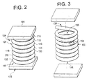
- air core inductor 100 includes an inductor portion 104 having a plurality of coils 114-120 that define an inductor member 124.
- Inductor member 124 includes a first end portion 134 a second end portion 144 and an intermediate portion 150 that collectively define a hollow or air core portion 155.
- inductor member 124 defines an air core inductor.
- inductor member 124 is formed from a solid core electrical conductor such as copper.
- inductor member 124 is a hollow core electrical conductor having an interior conduit portion 158 such as illustrated in FIG. 3 .
- Interior conduit portion 158 serves as a cooling fluid conduit for air core conductor 100. More specifically, during operation, particularly at high current ratings, air core inductor 100 generates a considerable amount of heat. In order to dissipate the heat, a cooling fluid, such as water, is passed through interior conduit portion 158.
- a cooling fluid such as water
- air core inductor 100 includes first and second flux inhibiting members 164 and 174.
- first and second flux inhibiting members 164 and 174 are positioned adjacent first and second end portions 134 and 144 respectively.
- First and second flux inhibiting members 164 and 174 block stray magnetic flux and establish a shorter magnetic path for air core inductor 100.
- First and second flux inhibiting members 164 and 174 are preferably formed from a ferrous material such as ferrite, iron, steel and alloys thereof. However, other materials having qualities that would inhibit the magnetic flux could also be employed. As illustrated in Table 1.1 reproduced below, when in place, flux inhibiting members 164 and 174 reduce B-field or stray flux, at a point located 200 mm centered directly above first end portion 134 induction by a factor of about 6.47 times.
- various aspects of the present invention provide an air core inductor that does not spew stray magnetic flux about adjacent areas. That is, that various aspects of the present invention block or substantially inhibits stray flux emanating from air core inductor 100.
- air core inductor 100 can be placed in close proximity with other electrical and electrically conducting components without fear of damage caused by induction heating effects. In this manner, systems that employ air core inductors, and particularly high current rated air core inductors, can be constructed that are more compact than are currently possible while still providing control over high electrical currents.
- air core inductor 100 can be formed in a variety of configurations and shapes.
- the number coils employed in forming the air core inductor can vary. Also, while shown with two stray flux inhibiting members, the air core inductor can be provided with a single stray flux inhibiting member.
Landscapes
- Engineering & Computer Science (AREA)
- Power Engineering (AREA)
- Coils Or Transformers For Communication (AREA)
- Regulation Of General Use Transformers (AREA)
Applications Claiming Priority (1)
| Application Number | Priority Date | Filing Date | Title |
|---|---|---|---|
| US11/939,102 US20090121818A1 (en) | 2007-11-13 | 2007-11-13 | Air core inductor including a flux inhibiting member |
Publications (2)
| Publication Number | Publication Date |
|---|---|
| EP2061046A2 true EP2061046A2 (de) | 2009-05-20 |
| EP2061046A3 EP2061046A3 (de) | 2012-02-22 |
Family
ID=40342318
Family Applications (1)
| Application Number | Title | Priority Date | Filing Date |
|---|---|---|---|
| EP08167892A Withdrawn EP2061046A3 (de) | 2007-11-13 | 2008-10-30 | Luftkerninduktor mit flusshemmendem Element |
Country Status (4)
| Country | Link |
|---|---|
| US (1) | US20090121818A1 (de) |
| EP (1) | EP2061046A3 (de) |
| JP (1) | JP2009124144A (de) |
| CN (1) | CN101499359A (de) |
Families Citing this family (2)
| Publication number | Priority date | Publication date | Assignee | Title |
|---|---|---|---|---|
| CN102163488A (zh) * | 2010-11-25 | 2011-08-24 | 文泽生 | 非晶油浸式全磁屏蔽空芯电抗器 |
| US10529478B2 (en) * | 2016-08-09 | 2020-01-07 | Mitsubishi Electric Corporation | Air core type reactor unit and electric power supply equipment having an air core type reactor unit |
Family Cites Families (12)
| Publication number | Priority date | Publication date | Assignee | Title |
|---|---|---|---|---|
| GB630353A (en) * | 1947-09-18 | 1949-10-11 | Gen Electric Co Ltd | Improvements in or relating to electric inductances |
| DE1151869B (de) * | 1960-07-11 | 1963-07-25 | Licentia Gmbh | Kernlose Starkstromdrosselspule mit magnetisch leitenden Jochen |
| JPS5691413A (en) * | 1979-12-26 | 1981-07-24 | Hitachi Ltd | Three phase reactor |
| JPS57832A (en) * | 1980-06-02 | 1982-01-05 | Hitachi Ltd | Magnetron |
| JPS5759311A (en) * | 1980-09-26 | 1982-04-09 | Toshiba Corp | Air-core type shunt reactor |
| JPH02116106A (ja) * | 1988-10-26 | 1990-04-27 | Matsushita Electric Ind Co Ltd | 磁性体テープ |
| JPH07231586A (ja) * | 1993-09-08 | 1995-08-29 | Tokin Corp | コードレスパワーステーション |
| US6262638B1 (en) * | 1998-09-28 | 2001-07-17 | Axcelis Technologies, Inc. | Tunable and matchable resonator coil assembly for ion implanter linear accelerator |
| JP4166886B2 (ja) * | 1998-12-18 | 2008-10-15 | 株式会社東芝 | 定着装置 |
| JP2002535727A (ja) * | 1999-01-19 | 2002-10-22 | クリストファー・イアン・キンマン | 増幅弦楽器ピックアップのためのノイズ検知ボビンコイルアセンブリ |
| JP2001093740A (ja) * | 1999-09-20 | 2001-04-06 | Toshiba Corp | 空心リアクトル及びその分解輸送方法 |
| WO2004064084A2 (en) * | 2003-01-03 | 2004-07-29 | Nucore, Inc. | Self-damped inductor |
-
2007
- 2007-11-13 US US11/939,102 patent/US20090121818A1/en not_active Abandoned
-
2008
- 2008-10-30 EP EP08167892A patent/EP2061046A3/de not_active Withdrawn
- 2008-11-11 JP JP2008288366A patent/JP2009124144A/ja not_active Withdrawn
- 2008-11-13 CN CNA2008101733324A patent/CN101499359A/zh active Pending
Also Published As
| Publication number | Publication date |
|---|---|
| JP2009124144A (ja) | 2009-06-04 |
| EP2061046A3 (de) | 2012-02-22 |
| US20090121818A1 (en) | 2009-05-14 |
| CN101499359A (zh) | 2009-08-05 |
Similar Documents
| Publication | Publication Date | Title |
|---|---|---|
| US6657529B1 (en) | Magnetic component | |
| US7427910B2 (en) | Winding structure for efficient switch-mode power converters | |
| US5210513A (en) | Cooling of electromagnetic apparatus | |
| EP3683811B1 (de) | Integrierte magnetische komponente | |
| US7446642B2 (en) | Inductor | |
| CN108806931A (zh) | 电磁兼容性滤波器 | |
| US20090096565A1 (en) | Parallel gapped ferrite core | |
| US7889040B2 (en) | DC inductor | |
| CN105518810A (zh) | 集成磁性组件及其组装方法 | |
| US20100321143A1 (en) | Inductor | |
| AU2011217733B2 (en) | Power supply improvements | |
| US20220328243A1 (en) | Magnetic component and power converter | |
| EP2061046A2 (de) | Luftkerninduktor mit flusshemmendem Element | |
| US20210193368A1 (en) | Power transformer and method for manufacturing the same | |
| CN114730654A (zh) | 电磁感应装置 | |
| JPH07503359A (ja) | 強磁性ワイヤ電磁アクチュエータ | |
| KR101088171B1 (ko) | 냉각 파이프를 구비하는 주상변압기 | |
| CN213583414U (zh) | 用于mri梯度功率放大器的高频大功率电感器 | |
| EP3544034A1 (de) | Verbindungseinheit für ein kontaktloses netzteil, kontaktloses netzteil und arbeitsmaschine | |
| US9111678B2 (en) | Planar core-type uniform external field equalizer and fabrication | |
| CN118571609A (zh) | 磁集成变压器、开关电源及电器 | |
| Mokkapaty et al. | 3D Finite Element analysis of magnetic shunts and aluminum shields in clamping frames of distribution transformers | |
| JPH0864436A (ja) | 磁気シールドトランス | |
| CN112466629A (zh) | 用于mri梯度功率放大器的高频大功率电感器 | |
| JP2002164235A (ja) | リーケージトランス、電源装置および照明器具 |
Legal Events
| Date | Code | Title | Description |
|---|---|---|---|
| PUAI | Public reference made under article 153(3) epc to a published international application that has entered the european phase |
Free format text: ORIGINAL CODE: 0009012 |
|
| AK | Designated contracting states |
Kind code of ref document: A2 Designated state(s): AT BE BG CH CY CZ DE DK EE ES FI FR GB GR HR HU IE IS IT LI LT LU LV MC MT NL NO PL PT RO SE SI SK TR |
|
| AX | Request for extension of the european patent |
Extension state: AL BA MK RS |
|
| PUAL | Search report despatched |
Free format text: ORIGINAL CODE: 0009013 |
|
| AK | Designated contracting states |
Kind code of ref document: A3 Designated state(s): AT BE BG CH CY CZ DE DK EE ES FI FR GB GR HR HU IE IS IT LI LT LU LV MC MT NL NO PL PT RO SE SI SK TR |
|
| AX | Request for extension of the european patent |
Extension state: AL BA MK RS |
|
| RIC1 | Information provided on ipc code assigned before grant |
Ipc: H01F 27/28 20060101ALN20120116BHEP Ipc: H01F 27/34 20060101ALI20120116BHEP Ipc: H01F 37/00 20060101ALI20120116BHEP Ipc: H01F 27/36 20060101AFI20120116BHEP |
|
| AKY | No designation fees paid | ||
| REG | Reference to a national code |
Ref country code: DE Ref legal event code: R108 Effective date: 20121031 |
|
| STAA | Information on the status of an ep patent application or granted ep patent |
Free format text: STATUS: THE APPLICATION IS DEEMED TO BE WITHDRAWN |
|
| 18D | Application deemed to be withdrawn |
Effective date: 20120823 |