EP2061052A2 - Dispositif de commutation destiné à applications en courant continu - Google Patents
Dispositif de commutation destiné à applications en courant continu Download PDFInfo
- Publication number
- EP2061052A2 EP2061052A2 EP08019483A EP08019483A EP2061052A2 EP 2061052 A2 EP2061052 A2 EP 2061052A2 EP 08019483 A EP08019483 A EP 08019483A EP 08019483 A EP08019483 A EP 08019483A EP 2061052 A2 EP2061052 A2 EP 2061052A2
- Authority
- EP
- European Patent Office
- Prior art keywords
- current path
- switching contact
- movable
- contact element
- current
- Prior art date
- Legal status (The legal status is an assumption and is not a legal conclusion. Google has not performed a legal analysis and makes no representation as to the accuracy of the status listed.)
- Withdrawn
Links
- 239000003990 capacitor Substances 0.000 claims abstract description 45
- 238000000926 separation method Methods 0.000 claims abstract description 39
- 238000010791 quenching Methods 0.000 claims abstract description 36
- 230000000171 quenching effect Effects 0.000 claims abstract description 36
- 230000008033 biological extinction Effects 0.000 claims description 3
- 230000015572 biosynthetic process Effects 0.000 claims description 3
- 238000010891 electric arc Methods 0.000 abstract 1
- 238000004519 manufacturing process Methods 0.000 abstract 1
- 230000005405 multipole Effects 0.000 description 7
- 238000002955 isolation Methods 0.000 description 3
- 230000006378 damage Effects 0.000 description 2
- 238000007664 blowing Methods 0.000 description 1
- 238000007596 consolidation process Methods 0.000 description 1
- 238000007599 discharging Methods 0.000 description 1
- 230000003628 erosive effect Effects 0.000 description 1
- 230000005923 long-lasting effect Effects 0.000 description 1
- 238000012986 modification Methods 0.000 description 1
- 230000004048 modification Effects 0.000 description 1
- 230000002265 prevention Effects 0.000 description 1
Images

Classifications
-
- H—ELECTRICITY
- H01—ELECTRIC ELEMENTS
- H01H—ELECTRIC SWITCHES; RELAYS; SELECTORS; EMERGENCY PROTECTIVE DEVICES
- H01H9/00—Details of switching devices, not covered by groups H01H1/00 - H01H7/00
- H01H9/30—Means for extinguishing or preventing arc between current-carrying parts
- H01H9/40—Multiple main contacts for the purpose of dividing the current through, or potential drop along, the arc
-
- H—ELECTRICITY
- H01—ELECTRIC ELEMENTS
- H01H—ELECTRIC SWITCHES; RELAYS; SELECTORS; EMERGENCY PROTECTIVE DEVICES
- H01H33/00—High-tension or heavy-current switches with arc-extinguishing or arc-preventing means
- H01H33/02—Details
- H01H33/59—Circuit arrangements not adapted to a particular application of the switch and not otherwise provided for, e.g. for ensuring operation of the switch at a predetermined point in the AC cycle
- H01H33/596—Circuit arrangements not adapted to a particular application of the switch and not otherwise provided for, e.g. for ensuring operation of the switch at a predetermined point in the AC cycle for interrupting DC
Definitions
- the invention relates to a switching device for DC applications, using components of switching devices for AC applications, eg. As circuit breaker, circuit breaker, switch disconnector, residual current circuit breaker is constructed.
- switching devices which have a plurality of current paths, which in turn comprise fixed and movable switching contact elements.
- the movable switching contact elements are movable together between a closed position, in which the mutually associated movable and stationary switching contact elements, and an open position, in which forms an insulating gap between the mutually associated movable and stationary switching contact elements.
- arc quenching devices such as arc guide rails, arc splitter stacks or Deion packages. These arcing devices divide the arcs into individual partial arcs; if the arc voltages are higher than the driving voltages, the arcs are safely erased.
- the arc erasure is thereby favors that the current has a natural zero crossing.
- a flashback of the arcs may occur; At high currents, such a large self-magnetic field is generated, which deflects the arcs automatically toward the arc quenching devices and finally extinguished.
- blowing magnets which generate a magnetic field with a strength and orientation which exert on the arcs a deflection force (Lorenz force), which deflects the arcs toward the arc extinguishing devices.
- Lorenz force deflection force
- the arcs are stretched as known per se, cooled and divided into partial arcs and thereby extinguished.
- Switching devices of the aforementioned type for AC applications are, for example, in DE 103 52 934 B4 .
- the object of the invention is to be able to inexpensively produce switching devices with DC breaking capacity and separation function.
- a multi-pole AC voltage switching device has a plurality of current paths (usually at least three), which are arranged side by side in a housing and at the same time can be closed and opened.
- Each current path has a movable switching contact element and at least one fixed switching contact element assigned to the respective movable switching contact element. In the open position of each current path forms between the two switching contact elements, an isolating distance, along which an arc can occur when the switching device is turned off under load, which can lead to damage to the switching device.
- the essence of the invention is such a conventional multi-pole AC switching device (such as a motor protection switch) to be connected by means of a capacitor so that on the one hand the switching arc is reliably deleted in a short time and on the other hand, the separation property of the switching device is maintained.
- This is achieved according to the invention in that the at least three current paths are subdivided into a first current path group and a second current path group, each of which comprises at least one current path. Parallel to the separation path of the first current path or current paths (current path of the first current path group), a quenching capacitor is now switched.
- the at least one current path of the second current path group can be connected in series with the first current path.
- the multi-pole AC switching device thus has in the circuit according to the invention at least a first and at least one second current path, which are in series, which is either directly, ie within the switching device or external wiring of the switching device or in the wiring of the switching device within a DC circuit z. B. can be realized via the connected to the switching device consumer; the at least one second current path, the consumer and the at least one first current path are then in series.
- the quenching capacitor is located parallel to the separating path of the at least one first current path, which is why the separating path of this current path is more specifically an opening path, since the separating function required according to EN60947-3, for example, can not be realized by the separating path with a quenching capacitor connected in parallel.
- the quenching capacitor is connected in parallel with an isolating path, it is always spoken of the isolating path of the current path.
- the quenching capacitor thus provides (reliable) for the prevention of the emergence and / or extinction of the arc over the separation path of the at least one first current path in a very short time, whereby the current flow through the series connection of both current paths and, if the switching device is part of a DC Circle is, the entire DC circuit is interrupted.
- the separation path of the at least one second current path ensures the required separation function, whereby the switching device thus switched on now DC switching capability in the small to medium current range while ensuring the separation function has. In this way, it has thus been possible to optimize by conventional modifications of a conventional three- or four- or multi-pole AC switching device such that it now provides DC switching capacity and separation function.
- the quenching capacitor is switched parallel to one of the three current paths (first current path), while the other two current paths (second current paths) initially remain unchanged. Furthermore, one of the two second current paths is connected in series with the first current path, which is effected by corresponding direct connection of the two current paths or when the switching device is integrated into the DC circuit by circuitry.
- the separation path of the second current path connected in series with the first current path serves to separate one pole of the DC circuit, while the separation path of the remaining second current path serves to separate the other pole of the DC switching device (three-pole switch with safe bipolar separation of the DC circuit).
- the parallel connection of the quenching capacitor to several in series (first) current paths of the switching device has the advantage that the capacity of the Capacitor can be reduced due to the higher voltage consolidation of the multiple separation sections.
- a discharge resistor in parallel to the quenching capacitor. This discharge resistor ensures a discharge of the quenching capacitor in the off state of the switching device, so as to avoid a "hard” discharging of the capacitor via the switching contact elements at a renewed switching of the switching device.
- Conventional multi-pole AC switching devices are provided with current paths, each having a movable switching contact element and two opposing fixed switching contact elements.
- the movable switching contact element connects the two fixed switching contact elements.
- Such a flow path comprises two separation paths along which arcs can form.
- the quenching capacitor is then parallel to the series connection of the two separation sections of a current path after capacitive wiring according to the invention.
- the common closing of all current paths is usually carried out in conventional multi-pole AC switching devices by operation of a so-called switching mechanism, which takes place by manual or otherwise successful operation of an actuating element (for example, toggle switch).
- an actuating element for example, toggle switch.
- the movable switching contact elements of all current paths are locked in their closed positions by the switch lock, which is switched off depending on the design of the switching device as, for example, circuit breaker on various events (for example, excessive current due to short circuit), so that all current paths are transferred simultaneously in their open positions.
- Fig. 1 shows a first embodiment of a switching device 10, which is designed for AC applications and connected in such a way to use this switching device 10 for the separation of DC circuits can.
- the switching device 10 has a housing schematically shown at 12, which has three current paths 14 in this embodiment.
- Each current path 14 comprises two fixed switching contact elements 16, 18, which can be electrically connected or disconnected by a respective movable switching contact element 20.
- two separating paths 22, 24 are formed per current path 14. All movable switching contact elements 20 are movable via a switching mechanism 26 (common actuating device) between the open and closed positions.
- Fig. 1 is one of the three current paths 14, namely the middle of the three current paths 14, provided with an erase capacitor 28 which is connected in parallel to the current path 14.
- This current path 14 is referred to below as the first current path 30, while the two other current paths 14 can be referred to as second current paths 32.
- These two second current paths 32 have no quenching capacitor connected in parallel.
- a (discharge) resistor 34 is parallel to the quenching capacitor 28 a (discharge) resistor 34.
- an external circuit see electrical connection 36
- one of the second current paths 32 and the first current path 30 are connected in series with each other.
- the switching device 10 is switched to a direct current circuit, it is located between an infeed (for example, a solar system) and a load or a consumer.
- the one pole (in this embodiment the negative pole) of the DC circuit is switched via the one of the two second current paths 32, namely the second current path 32, which is not connected in series with the first current path 30.
- the other pole (in this embodiment, the positive pole) of the DC circuit is connected to the series circuit of the other second current path 32 and the first current path 30.
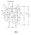
- Fig. 2 shows a second embodiment of a possible capacitive circuit of a switching device 10 'for AC applications for use as a separation of DC circuits.
- the individual components of the wiring according to Fig. 2 structurally the same or functionally identical to the individual components Fig. 1 are, they are in Fig. 2 provided with the same reference numerals.
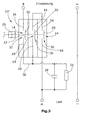
- FIG Fig. 3 Another embodiment of a capacitive circuit of an ac switchgear 10 "for use with the dc disconnect function is shown in FIG Fig. 3 shown.
- the individual components of the wiring according to Fig. 3 structurally the same or functionally identical to the individual components Fig. 1 are, they are in Fig. 3 provided with the same reference numerals.
- the quenching capacitor 28 is connected in parallel to the series connection of two (first) current paths 30 with a parallel discharge resistor 34.
- discharge resistor 34 and the two successive first current paths 30 is the remaining third current path, which takes over the function of the above-described current path 32 of the second group.
- the second current path 32 takes over according to Fig. 3 the physical separation function in one of the two poles (in the embodiment of the positive pole) of the DC circuit.
- the negative pole has no current path in this embodiment, but could be realized by the then available fourth current path when using a four-pole conventional AC switching device.
- the quenching capacitor 32 is connected in parallel to a plurality of series-connected first current paths 30.
- the capacitance of the capacitor can be reduced due to the higher voltage hardening of the multiplied separating sections.
Landscapes
- Engineering & Computer Science (AREA)
- Power Engineering (AREA)
- Arc-Extinguishing Devices That Are Switches (AREA)
Applications Claiming Priority (1)
| Application Number | Priority Date | Filing Date | Title |
|---|---|---|---|
| DE102007054960A DE102007054960B3 (de) | 2007-11-17 | 2007-11-17 | Schaltgerät für Gleichstrom-Anwendungen |
Publications (2)
| Publication Number | Publication Date |
|---|---|
| EP2061052A2 true EP2061052A2 (fr) | 2009-05-20 |
| EP2061052A3 EP2061052A3 (fr) | 2012-04-04 |
Family
ID=40342135
Family Applications (1)
| Application Number | Title | Priority Date | Filing Date |
|---|---|---|---|
| EP08019483A Withdrawn EP2061052A3 (fr) | 2007-11-17 | 2008-11-07 | Dispositif de commutation destiné à applications en courant continu |
Country Status (3)
| Country | Link |
|---|---|
| US (1) | US20090127230A1 (fr) |
| EP (1) | EP2061052A3 (fr) |
| DE (1) | DE102007054960B3 (fr) |
Cited By (4)
| Publication number | Priority date | Publication date | Assignee | Title |
|---|---|---|---|---|
| EP2249393A1 (fr) * | 2009-05-04 | 2010-11-10 | voltwerk electronics GmbH | Agencement de circuit |
| WO2013081851A1 (fr) * | 2011-12-02 | 2013-06-06 | Schneider Electric USA, Inc. | Combinateur de chaînes photovoltaïques à dispositif de déconnexion possédant un moyen de conversion entre systèmes mis à la masse et ceux non mis à la masse |
| WO2013176940A1 (fr) * | 2012-05-22 | 2013-11-28 | Schneider Electric USA, Inc. | Moyen de débranchement amovible et d'isolement pour application en courant continu |
| EP2819135A1 (fr) * | 2013-06-25 | 2014-12-31 | Schneider Electric Industries SAS | Contacteur électrique et procédé de commande d'un tel contacteur |
Families Citing this family (2)
| Publication number | Priority date | Publication date | Assignee | Title |
|---|---|---|---|---|
| DE102009022508A1 (de) * | 2009-05-25 | 2010-12-09 | Eaton Industries Gmbh | Safety-Schaltanlage für Solaranlagen |
| WO2016169612A1 (fr) * | 2015-04-24 | 2016-10-27 | Abb Technology Ltd | Commutateur de dérivation comprenant un élément mobile avec une première section conductrice et une deuxième section conductrice |
Citations (6)
| Publication number | Priority date | Publication date | Assignee | Title |
|---|---|---|---|---|
| EP0217106B1 (fr) | 1985-08-30 | 1991-10-16 | Licentia Patent-Verwaltungs-GmbH | Dispositif d'extinction pour disjoncteur de puissance tout courant |
| EP1594148A1 (fr) | 2004-05-05 | 2005-11-09 | ABB PATENT GmbH | Dispositif d'extinction d'arc pour disjoncteur |
| DE10352934B4 (de) | 2003-11-11 | 2005-12-22 | Siemens Ag | Lichtbogen-Löschvorrichtung |
| DE202005007878U1 (de) | 2005-05-19 | 2006-09-28 | Schaltbau Gmbh | Löschkammer |
| DE10212948B4 (de) | 2001-03-28 | 2006-11-09 | Schaltbau Gmbh | Schütz für AC- und DC-Betrieb |
| EP0980085B1 (fr) | 1998-08-13 | 2006-11-22 | Siemens Aktiengesellschaft | Disjoncteur de puissance à bobine de soufflage actionné par l'arc |
Family Cites Families (11)
| Publication number | Priority date | Publication date | Assignee | Title |
|---|---|---|---|---|
| DE1126479B (de) * | 1957-10-11 | 1962-03-29 | Bbc Brown Boveri & Cie | Kontaktbrueckentraeger fuer ein elektromagnetisches Schuetz |
| CH380800A (de) * | 1960-09-16 | 1964-08-15 | Bbc Brown Boveri & Cie | Leistungsschalter mit Mehrfachunterbrechung |
| DE1874564U (de) * | 1963-04-09 | 1963-06-27 | Continental Elektro Ind Ag | Schaltkammer fuer gleichstromschaltgeraete, insbesondere gleichstromschuetze. |
| DE2022178A1 (de) * | 1970-05-06 | 1971-11-18 | Bbc Brown Boveri & Cie | Kontaktanordnung mit Schaltbruecke |
| DE2234423A1 (de) * | 1972-07-13 | 1974-01-24 | Bbc Brown Boveri & Cie | Installationsselbstschalter in schalenbauweise |
| DE7602660U1 (de) * | 1976-01-31 | 1976-07-22 | Kloeckner-Moeller Elektrizitaets- Gmbh, 5300 Bonn | Mehrpoliger Leitungsschutzschalter bzw. Kleinselbstschalter für höheres Gleichspannungsschaltvermögen |
| DE2802556A1 (de) * | 1978-01-19 | 1979-07-26 | Licentia Gmbh | Schaltanordnung zum abschalten von gleichstroemen grosser stromstaerke bei hohen spannungen |
| JP3135338B2 (ja) * | 1992-02-21 | 2001-02-13 | 株式会社日立製作所 | 転流式直流遮断器 |
| JP3501886B2 (ja) * | 1995-04-28 | 2004-03-02 | 三菱電機株式会社 | 自励転流式直流遮断装置及びその容量設定方法 |
| DE102006004182B3 (de) * | 2006-01-27 | 2007-10-18 | Powerlynx A/S | Leistungswandler mit einer Schalteinrichtung |
| US7551050B2 (en) * | 2006-09-22 | 2009-06-23 | Rockwell Automation Technologies, Inc. | Contactor assembly with arc steering system |
-
2007
- 2007-11-17 DE DE102007054960A patent/DE102007054960B3/de not_active Expired - Fee Related
-
2008
- 2008-11-07 EP EP08019483A patent/EP2061052A3/fr not_active Withdrawn
- 2008-11-14 US US12/271,672 patent/US20090127230A1/en not_active Abandoned
Patent Citations (6)
| Publication number | Priority date | Publication date | Assignee | Title |
|---|---|---|---|---|
| EP0217106B1 (fr) | 1985-08-30 | 1991-10-16 | Licentia Patent-Verwaltungs-GmbH | Dispositif d'extinction pour disjoncteur de puissance tout courant |
| EP0980085B1 (fr) | 1998-08-13 | 2006-11-22 | Siemens Aktiengesellschaft | Disjoncteur de puissance à bobine de soufflage actionné par l'arc |
| DE10212948B4 (de) | 2001-03-28 | 2006-11-09 | Schaltbau Gmbh | Schütz für AC- und DC-Betrieb |
| DE10352934B4 (de) | 2003-11-11 | 2005-12-22 | Siemens Ag | Lichtbogen-Löschvorrichtung |
| EP1594148A1 (fr) | 2004-05-05 | 2005-11-09 | ABB PATENT GmbH | Dispositif d'extinction d'arc pour disjoncteur |
| DE202005007878U1 (de) | 2005-05-19 | 2006-09-28 | Schaltbau Gmbh | Löschkammer |
Cited By (7)
| Publication number | Priority date | Publication date | Assignee | Title |
|---|---|---|---|---|
| EP2249393A1 (fr) * | 2009-05-04 | 2010-11-10 | voltwerk electronics GmbH | Agencement de circuit |
| US8614865B2 (en) | 2009-05-04 | 2013-12-24 | Voltwerk Electronics Gmbh | Circuit arrangement |
| WO2013081851A1 (fr) * | 2011-12-02 | 2013-06-06 | Schneider Electric USA, Inc. | Combinateur de chaînes photovoltaïques à dispositif de déconnexion possédant un moyen de conversion entre systèmes mis à la masse et ceux non mis à la masse |
| US9397235B2 (en) | 2011-12-02 | 2016-07-19 | Schneider Elelctric Usa, Inc. | Photovoltaic string combiner with disconnect having provision for converting between grounded and ungrounded systems |
| WO2013176940A1 (fr) * | 2012-05-22 | 2013-11-28 | Schneider Electric USA, Inc. | Moyen de débranchement amovible et d'isolement pour application en courant continu |
| US8743531B2 (en) | 2012-05-22 | 2014-06-03 | Schneider Electric USA, Inc. | Drawout disconnecting and isolating means for DC applications |
| EP2819135A1 (fr) * | 2013-06-25 | 2014-12-31 | Schneider Electric Industries SAS | Contacteur électrique et procédé de commande d'un tel contacteur |
Also Published As
| Publication number | Publication date |
|---|---|
| US20090127230A1 (en) | 2009-05-21 |
| EP2061052A3 (fr) | 2012-04-04 |
| DE102007054960B3 (de) | 2009-04-23 |
Similar Documents
| Publication | Publication Date | Title |
|---|---|---|
| EP2383761A1 (fr) | Commutateur destiné à des applications à courant continu | |
| EP3084960B1 (fr) | Dispositif de commutation pour le passage et la coupure de courants électriques | |
| EP3158571A1 (fr) | Dispositif de coupure pour interrompre un courant continu | |
| WO2012076606A1 (fr) | Interrupteur à chambre d'extinction | |
| EP3428942B1 (fr) | Dispositif d'extinction d'arc de courant continu et appareil de commutation de courant continu électromécanique | |
| DE102011089234B4 (de) | Lichtbogen-Löschvorrichtung und Schutzschaltgerät | |
| DE102007054960B3 (de) | Schaltgerät für Gleichstrom-Anwendungen | |
| DE102016120070A1 (de) | Niederspannungs-Schutzschaltgerät | |
| DE19912022B4 (de) | Hochspannungsschaltgerät mit Serienschaltung von mindestens zwei Vakuumschaltkammern und Verfahren zum Betrieb des Hochspannungsschallgerätes | |
| DE69315786T2 (de) | Leitungsschutzschalter mit magnetischer Blasschleife | |
| EP0350825B1 (fr) | Appareil de commutation électrique | |
| EP1384240B1 (fr) | Procede pour faire fonctionner un commutateur presentant un limiteur de courant qui peut etre raccorde et dispositif associe | |
| EP3084794B1 (fr) | Dispositif de commutation | |
| DE19956698C1 (de) | Anordnung mit zwei Schützen in Reihenschaltung | |
| EP2393096B1 (fr) | Appareil de commutation basse tension pouvant être interrompu facilement, notamment commutateur de protection de ligne | |
| EP1615246A1 (fr) | Dispositif d'extinction d'arc pour un disjoncteur | |
| EP3050069B1 (fr) | Un dispositif de commutation et procédé de coupure de fonctionnement d'un dispositif de commutation | |
| DE102007004528B3 (de) | Elektrisches Gleichstromnetz für Wasserfahrzeuge sowie für Offshoreanlagen mit erhöhter Abschaltsicherheit | |
| EP2541574B1 (fr) | Disjoncteur électrique à double point de rupture | |
| WO2020064109A1 (fr) | Disjoncteur basse tension | |
| EP3889986A1 (fr) | Disjoncteur de protection compact électromécanique | |
| DE102020205784A1 (de) | Schaltgerät mit Kommutierungsstrompfad | |
| EP2915174B1 (fr) | Dispositif de commutation à courant continu | |
| DE102012208573A1 (de) | Lichtbogen-Löschvorrichtung und Schutzschaltgerät | |
| DE102019207199A1 (de) | Polaritätsunabhängige Gleichstrom-Lichtbogenlöschvorrichtung, polaritätsunabhängiges Gleichstrom-Schaltgerät sowie Schaltgeräte-Anordnung |
Legal Events
| Date | Code | Title | Description |
|---|---|---|---|
| PUAI | Public reference made under article 153(3) epc to a published international application that has entered the european phase |
Free format text: ORIGINAL CODE: 0009012 |
|
| AK | Designated contracting states |
Kind code of ref document: A2 Designated state(s): AT BE BG CH CY CZ DE DK EE ES FI FR GB GR HR HU IE IS IT LI LT LU LV MC MT NL NO PL PT RO SE SI SK TR |
|
| AX | Request for extension of the european patent |
Extension state: AL BA MK RS |
|
| RAP1 | Party data changed (applicant data changed or rights of an application transferred) |
Owner name: EATON INDUSTIES GMBH |
|
| RAP1 | Party data changed (applicant data changed or rights of an application transferred) |
Owner name: EATON INDUSTRIES GMBH |
|
| PUAL | Search report despatched |
Free format text: ORIGINAL CODE: 0009013 |
|
| AK | Designated contracting states |
Kind code of ref document: A3 Designated state(s): AT BE BG CH CY CZ DE DK EE ES FI FR GB GR HR HU IE IS IT LI LT LU LV MC MT NL NO PL PT RO SE SI SK TR |
|
| AX | Request for extension of the european patent |
Extension state: AL BA MK RS |
|
| RIC1 | Information provided on ipc code assigned before grant |
Ipc: H01H 33/59 20060101ALI20120228BHEP Ipc: H01H 9/40 20060101AFI20120228BHEP |
|
| AKY | No designation fees paid | ||
| REG | Reference to a national code |
Ref country code: DE Ref legal event code: R108 |
|
| REG | Reference to a national code |
Ref country code: DE Ref legal event code: R108 Effective date: 20121212 |
|
| STAA | Information on the status of an ep patent application or granted ep patent |
Free format text: STATUS: THE APPLICATION IS DEEMED TO BE WITHDRAWN |
|
| 18D | Application deemed to be withdrawn |
Effective date: 20121005 |