EP2061279B1 - Vorrichtung zur Lokalisierung einer virtuellen Klangquelle - Google Patents
Vorrichtung zur Lokalisierung einer virtuellen Klangquelle Download PDFInfo
- Publication number
- EP2061279B1 EP2061279B1 EP08169126.3A EP08169126A EP2061279B1 EP 2061279 B1 EP2061279 B1 EP 2061279B1 EP 08169126 A EP08169126 A EP 08169126A EP 2061279 B1 EP2061279 B1 EP 2061279B1
- Authority
- EP
- European Patent Office
- Prior art keywords
- loudspeakers
- listening position
- listener
- sound
- unit
- Prior art date
- Legal status (The legal status is an assumption and is not a legal conclusion. Google has not performed a legal analysis and makes no representation as to the accuracy of the status listed.)
- Ceased
Links
- 230000004807 localization Effects 0.000 title claims description 102
- 230000005236 sound signal Effects 0.000 claims description 117
- 238000012546 transfer Methods 0.000 claims description 33
- 230000006870 function Effects 0.000 claims description 30
- 230000003111 delayed effect Effects 0.000 claims description 15
- 210000005069 ears Anatomy 0.000 claims description 7
- 238000010586 diagram Methods 0.000 description 16
- 238000012937 correction Methods 0.000 description 12
- 230000000694 effects Effects 0.000 description 8
- 230000001934 delay Effects 0.000 description 7
- 238000005259 measurement Methods 0.000 description 7
- 238000000034 method Methods 0.000 description 6
- 238000012545 processing Methods 0.000 description 6
- 238000001514 detection method Methods 0.000 description 5
- 238000006243 chemical reaction Methods 0.000 description 3
- 230000014509 gene expression Effects 0.000 description 3
- 238000005457 optimization Methods 0.000 description 2
- 230000002238 attenuated effect Effects 0.000 description 1
- 230000001419 dependent effect Effects 0.000 description 1
- 238000006073 displacement reaction Methods 0.000 description 1
Images




Classifications
-
- H—ELECTRICITY
- H04—ELECTRIC COMMUNICATION TECHNIQUE
- H04S—STEREOPHONIC SYSTEMS
- H04S7/00—Indicating arrangements; Control arrangements, e.g. balance control
- H04S7/30—Control circuits for electronic adaptation of the sound field
- H04S7/302—Electronic adaptation of stereophonic sound system to listener position or orientation
-
- H—ELECTRICITY
- H04—ELECTRIC COMMUNICATION TECHNIQUE
- H04S—STEREOPHONIC SYSTEMS
- H04S2400/00—Details of stereophonic systems covered by H04S but not provided for in its groups
- H04S2400/01—Multi-channel, i.e. more than two input channels, sound reproduction with two speakers wherein the multi-channel information is substantially preserved
-
- H—ELECTRICITY
- H04—ELECTRIC COMMUNICATION TECHNIQUE
- H04S—STEREOPHONIC SYSTEMS
- H04S2400/00—Details of stereophonic systems covered by H04S but not provided for in its groups
- H04S2400/11—Positioning of individual sound objects, e.g. moving airplane, within a sound field
-
- H—ELECTRICITY
- H04—ELECTRIC COMMUNICATION TECHNIQUE
- H04S—STEREOPHONIC SYSTEMS
- H04S2420/00—Techniques used stereophonic systems covered by H04S but not provided for in its groups
- H04S2420/01—Enhancing the perception of the sound image or of the spatial distribution using head related transfer functions [HRTF's] or equivalents thereof, e.g. interaural time difference [ITD] or interaural level difference [ILD]
Definitions
- the present invention relates to a virtual sound source localization apparatus that localizes virtual sound sources around a listener.
- a virtual surround apparatus in which multi-channel audio signals are reproduced from two loudspeakers arranged in front of a listener to localize a plurality of virtual sound sources around the listener, thereby allowing the listener to feel a surround sense (a feeling of encirclement) as if a plurality of loudspeakers are arranged around the listener.
- a surround sense a feeling of encirclement
- virtual localization is imparted to the audio signals on the basis of head related transfer functions, but since a strict reproduction condition is applied, an optimum listening position where the listener feels the surround sense is limited. For this reason, if the listener changes a seat from the optimum listening position, the listener may not feel the surround sense.
- an apparatus in which a position detection unit for detecting the position of the listener detects the position of the listener, and a coefficient (correction coefficient) based on the head related transfer functions is selected in accordance with a zone where the listener is located, thereby changing sound image localization (see Patent Document 1).
- a position detection unit for detecting the position of the listener detects the position of the listener, and a coefficient (correction coefficient) based on the head related transfer functions is selected in accordance with a zone where the listener is located, thereby changing sound image localization
- the position of the listener is detected by an impulse sound wave emitted from the loudspeaker and a microphone or a camera to measure a distance between the two loudspeakers and the head (ears) of the listener, and sound image localization is set on the basis of the distance (see Patent Document 2).
- US 2006/0062410 A1 relates to a method of reproducing a virtual sound to reproduce a two-channel virtual sound from a 5.1 channel sound using a two-channel speaker system.
- the method includes generating a two-channel virtual sound from a multi-channel sound, sensing a listener position with respect to two speakers, generating a listener position compensation value by calculating output levels and tine delays of the two speakers with respect to the sensed listener position, and compensating output values of the generated two-channel virtual sound based on the listener position compensation value.
- the listener may not feel the surround sense. Accordingly, if a wide zone with a correction coefficient is set, the listener may not feel the surround sense at the end of the zone. If a narrow zone with a sound image localization coefficient is set, a plurality of sound image localization coefficients may be needed.
- An object of the invention is to provide a virtual sound source localization apparatus that adjusts a sound image localization position in accordance with a listening position of a listener, thereby allowing the listener to feel a surround sense, without needing a position detection unit for detecting the position of the listener or a plurality of sound image localization coefficients.
- the invention provides a virtual sound source localization apparatus according to claim 1.
- the dependent claims describe advantageous embodiments.
- the distance between the two loudspeakers is substantially identical to the horizontal width of the monitor, and a listening distance is determined by an optimum viewing distance of the monitor.
- the delay unit reads out the distance between the two loudspeakers according to the size of the monitor received by the input unit and the shortest distance between the line connecting the two loudspeakers and the listening position from the storage unit, and calculates the difference in distance by using the information and a distance in output level between the two loudspeakers balance-adjusted by the balance adjusting unit. Therefore, an input operation can be simplified, and it is possible to allow the listener to feel the surround sense in accordance with the operation of the operating unit by the listener, regardless of the listening position of the listener.
- a position detection unit for detecting the position of the listener or a plurality of correction coefficients are not needed, and the volume level (balance) and the delay amount are corrected depending on the listening position of the listener. Therefore, even though frequency characteristics according to an angle of the listening position with respect to the two loudspeakers are not corrected, the localized positions of the virtual sound sources can be adjusted, and thus the listener can sufficiently fee the surround sense.
- Fig. 1 is a block diagram showing the structure of a virtual sound source localization apparatus according to a first embodiment of the invention. It is assumed that a virtual sound source localization apparatus 1 shown in Fig. 1 reproduces surround sound of a 5-channel audio signal, which is an example of a multi-channel audio signal. Fig. 1 also shows a system structure in which a sound signal of video/sound contents, such as a television program or a movie, reproduced by a tuner 5 or a DVD player 6, is output to the virtual sound source localization apparatus 1, and a video signal of video/sound contents is output to a monitor 28. Then, the virtual sound source localization apparatus 1 emits virtual surround sound to a listener, and the monitor 28 displays video.
- a sound signal of video/sound contents such as a television program or a movie, reproduced by a tuner 5 or a DVD player 6
- a front-left channel is denoted by L (Left) ch
- a front-right channel is denoted by R (Right) ch
- a center channel is denoted by C (Center) ch
- a rear-left channel is denoted by SL (Surround Left) ch
- a rear-right channel is denoted by SR (Surround Right) ch.
- the virtual sound source localization apparatus (hereinafter, simply referred to as a localization apparatus) 1 includes a DSP (Digital Signal Processor) decoder 11, a signal processor 12, a D/A converter 13, an electronic volume 15, a power amplifier 16, a controller 17, a memory 18, an operating section 19, and a display 20.
- An Lch loudspeaker 21 and an Rch loudspeaker 22 are connected to the power amplifier 16 of the localization apparatus 1.
- the Lch loudspeaker 21 and the Rch loudspeaker 22 are provided at front-left and front-right positions of the monitor 28, respectively.
- the Lch loudspeaker 21 is provided at a front-left position with respect to a listening position 90 of a listener U
- the Rch loudspeaker 22 is provided at a front-right position with respect to the listening position 90 of the listener U.
- the localization apparatus 1 localizes an SLch virtual sound source 24 at a rear-left position with respect to the listening position 90 of the listener U, localizes an SRch virtual sound source 25 at a rear-right position with respect to the listening position 90 of the listener U, and localizes a Cch sound image 23 at a front-center position with respect to the listening position 90 of the listener U.
- a DIR (Digital audio Interface Receiver) 32, an A/D converter 34, and a digital interface, such as an HDMI (High Definition Multimedia Interface) (Registered Trademark) receiver 36 are connected to the DSP decoder 11.
- the DSP decoder 11 converts an analog sound signal or a digital bit stream, which is output from the tuner 5 through the A/D converter 34 or AV instrument, such as the DVD player 6, through the HDMI (Registered Trademark) receiver 36, into a 5-channel digital sound signal (PCM signal) and outputs the converted 5-channel digital sound signal to the signal processor 12.
- the DSP decoder 11 supports various data formats, and decodes an external input signal to a 5-channel digital audio signal (PCM signal) by using a decoder (not shown). When a 5-channel digital audio signal (PCM signal) is directly input from the DVD player 6, the DSP decoder 11 outputs the signal to the signal processor 12 as it is.
- the signal processor 12 has an SLch localization adder 42 including an SLch direct localization adder 42D and an SLch indirect localization adder 42C, an SRch localization adder 46 including an SRch direct localization adder 46D and an SRch indirect localization adder 46C, adders 52 and 54, a crosstalk cancellation corrector 60 including an Lch direct corrector 62, an Lch cross corrector 64, an Rch direct corrector 66, and an Rch cross corrector 68, adders 72 to 75, delay correctors 81 L and 81 R, and level correctors 84L and 84R.
- SLch localization adder 42 including an SLch direct localization adder 42D and an SLch indirect localization adder 42C
- an SRch localization adder 46 including an SRch direct localization adder 46D and an SRch indirect localization adder 46C
- adders 52 and 54 a crosstalk cancellation corrector 60 including an Lch direct corrector 62, an Lch cross correct
- the SLch direct localization adder 42D sets a filter coefficient and a delay time based on head related transfer functions from the sound source localized at the rear-left position of the listener U to the left ear EL of the listener U.
- the SLch indirect localization adder 42C sets a filter coefficient and a delay time based on the head related transfer functions from the sound source localized at the rear-left position of the listener U to the right ear ER of the listener U.
- the SRch direct localization adder 46D sets a filter coefficient and a delay time based on the head related transfer functions from the sound source localized at the rear-right position of the listener U to the right ear ER of the listener U.
- the SRch indirect localization adder 46C sets a filter coefficient and a delay time based on the head related transfer functions from the sound source localized at the rear-right position of the listener U to the left ear EL of the listener U.
- the head related transfer functions used for setting the filter coefficients and the delay time in the SLch localization adder 42 and the SRch localization adder 46 a set of head related transfer functions having general versatility are used, regardless of a listener or a viewing distance and an acoustic environment. The details of the head related transfer functions will be described below.
- head related transfer functions for example, head related transfer functions corresponding to a substantially even head shape may be used.
- the audio signals output from the SLch direct localization adder 42D and the SRch indirect localization adder 46C are added by the adder 52, and output to the Lch direct corrector 62 and the Lch cross corrector 64 of the crosstalk cancellation corrector 60.
- the audio signals output from the SRch direct localization adder 46D and the SLch indirect localization adder 42C are added by the adder 54, and output to the Rch direct corrector 66 and the Rch cross corrector 68 of the crosstalk cancellation corrector 60.
- a head related transfer function from the Lch loudspeaker 21 to the left ear EL of the listener U and a head related transfer function from the Rch loudspeaker 22 to the right ear ER of the listener U are fd.
- a head related transfer function from the Lch loudspeaker 21 to the right ear ER of the listener U and a head related transfer function from the Rch loudspeaker 22 to the left ear EL of the listener U are fc.
- a filter coefficient corresponding to a reversed function of the head related transfer function from the Lch loudspeaker 21 to the left ear EL of the listener U is set in the Lch direct corrector 62. That is, a filter coefficient fdl(fd 2 -fc 2 ) is set in the Lch direct corrector 62.
- the Lch direct corrector 62 cancels a propagation property from the Lch loudspeaker 21 to the left ear EL for each of the channel audio signals output from the adder 52 so as for the listener U not to recognize that sound of each channel is emitted from the Lch loudspeaker 21.
- each frequency component is attenuated, but it is low-raised by the amount of attenuation in the Lch direct corrector 62. Accordingly, the SLch and SRch audio signals output from the Lch direct corrector 62 have the frequency characteristics imparted by the localization adders 42D and 46C and the frequency characteristics with the propagation property from the Lch loudspeaker 21 to the left ear EL cancelled.
- a filter coefficient corresponding to a product of a reversed function of the head related transfer function from the Lch loudspeaker 21 to the left ear EL of the listener U and a reversed function of the head related transfer function from the Rch loudspeaker 22 to the right ear ER of the listener U is set in the Lch cross corrector 64. That is, a filter coefficient fc/(fd 2 -fc 2 ) is set in the Lch cross corrector 64.
- the Lch cross corrector 64 cancels a propagation property from the Lch loudspeaker 21 to the left ear EL and a propagation property from the Rch loudspeaker 22 to the right ear ER.
- the Lch cross corrector 64 performs the above-described processing on the channel audio signals output from the adder 52. Then, the audio signals are phase-inverted by a buffer (not shown), and are added by the adder 73. At this time, the output timings of the channel audio signals are adjusted such that a timing, at which an SLch added audio signal propagates to the right ear ER of the listener U after being emitted from the Rch loudspeaker 22, is identical to a timing, at which each channel audio signal propagates to the right ear ER of the listener U after being processed by the Lch direct corrector 62 and emitted from the Lch loudspeaker 21.
- the Rch direct corrector 66 and the Rch cross corrector 68 perform the same processing as the Lch direct corrector 62 and the Lch cross corrector 64, respectively.
- each channel emitted from the Lch loudspeaker 21 is listened only through the left ear EL of the listener U, and SLch and SRch sounds emitted from the Rch loudspeaker 22 are listened only through the right ear ER of the listener U.
- the SLch and SRch audio signals are given the frequency characteristics such that the sound sources are virtually localized at the rear-left and rear-right positions of the listener U.
- the channel audio signals emitted from the Lch loudspeaker 21 are given flat frequency characteristics so as for the listener U not to recognize that the audio signals are emitted from the Lch loudspeaker 21.
- the channel audio signals emitted from the Rch loudspeaker 22 are given flat frequency characteristics so as for the listener U not to recognize that the audio signals are emitted from the Rch loudspeaker 22. Therefore, the listener U can get a feeling of localization as if SLch and SRch sound is emitted from the virtual sound source virtually localized at the rear-left and rear-right positions of the listener U.
- the adder 72 adds the audio signals, which are output from the Lch direct corrector 62, and the audio signals, which are output from the Rch cross corrector 68 and inverted (multiplied by -1) by the buffer (not shown), and outputs the added audio signals to the adder 74.
- the adder 73 adds the audio signals, which are output from the Rch direct corrector 66, and the audio signals, which are output from the LCh cross corrector 64 and inverted (multiplied by -1) by the buffer (not shown), and outputs the added audio signals to the adder 75.
- the adder 74 adds the Lch audio signals and the Cch audio signals output from the DSP decoder 11, and the audio signals output from the adder 72, and outputs the added audio signals to the D/A converter 13.
- the adder 75 adds the Rch audio signals and the Cch audio signals output from the DSP decoder 11, and the audio signals output from the adder 73, and outputs the added audio signals to the D/A converter 13.
- the Lch loudspeaker 21 and the Rch loudspeaker 22 emits Cch sound at the same volume, and thus the localization apparatus 1 allows the listener U to get a feeling of localization as if the Cch sound image 23 is localized at the center of the Lch loudspeaker 21 and the Rch loudspeaker 22.
- the delay corrector 81 L delays the audio signals output from the adder 74 in accordance with a delay amount set by the controller 17.
- the delay corrector 81 R delays the audio signals output from the adder 75 in accordance with a delay amount set by the controller 17.
- the level corrector 84L adjusts the volume level of each of the audio signals output from the delay corrector 81 L to a volume level default by the controller 17 in accordance with an operation of a balance adjusting button 19B of the operating section 19.
- the level corrector 84R adjusts the volume level of each of the audio signals output from the delay corrector 81 R to a volume level default by the controller 17 in accordance with an operation of the balance adjusting button 19B of the operating section 19.
- the D/A converter 13 converts the digital audio signals of the five channels, that is, Lch, Rch, Cch, SLch, and SRch, output from the level correctors 84L and 84R of the signal processor 12 into analog audio signals.
- the electronic volume 15 adjusts the signal amount of the analog sound signal of each channel on the basis of a control signal from the controller 17 in accordance with an operation by a volume adjusting button 19V of the operating section 19.
- the power amplifier 16 amplifies the analog sound signals adjusted by the electronic volume 15 and outputs the amplified analog sound signals to the Lch loudspeaker 21 and the Rch loudspeaker 22.
- the Lch loudspeaker 21 and the Rch loudspeaker 22 emit sound based on the analog sound signals output from the power amplifier 16.
- the controller 17 controls the individual sections in accordance with an operation by the operating section 19. For example, if an operation to adjust a volume is performed by the operating section 19, the controller 17 outputs a control signal based on the corresponding operation to the electronic volume 15, to thereby change the volume of sound to be emitted from each of the loudspeakers 21 to 27.
- a CPU or an MPU is preferably used as the controller 17, a CPU or an MPU is preferably used. If the operating section 19 receives an input of information regarding a distance D between the loudspeakers or a listening distance H, the controller 17 controls the memory 18 to store the information.
- the memory 18 stores programs which are executed by the controller 17, or input data which is received by the operating section 19.
- the operating section 19 has the balance adjusting button 19B and the volume adjusting button 19V.
- a user inputs various operations and settings by the operating section 19 with respect to the localization apparatus 1.
- the operating section 19 receives the distance D between the loudspeakers or the listening distance H.
- the balance adjusting button 19B adjusts a volume balance such that the center channel sound source is at the approximately center of the two loudspeakers 21 and 22.
- the volume adjusting button 19V adjusts the volume (signal amount) of the analog sound signal of each channel.
- the operating section 19 may be incorporated into a remote controller, such that the listener U may remote control the localization apparatus 1 at the listening position.
- the display 20 displays a message from the localization apparatus 1 to the user.
- the sound balance (volume level) and the delay amount are changed depending on the position of the listener.
- a virtual surround effect is optimized such that the virtual sound sources are localized around the listener U, regardless of the listening position. That is, in the localization apparatus 1, if the multi-channel audio signal is input from the tuner 5 or the DVD player 6 to the signal processor 12 through the DIR 32, the A/D converter 34, or the DSP decoder 11, then the SLch localization adder 42 and the SRch localization adder 46 give virtual localization to the audio signals of the rear-left and rear-right channels.
- the crosstalk cancellation corrector 60 performs crosstalk cancellation.
- the adders 74 and 75 add the audio signals of the rear channels and other channels, and then multi-channel sound is emitted from the two loudspeakers 21 and 22 on the left and right sides in front of the listener U, such that a plurality of virtual sound sources are localized around the listener.
- the distance between the two loudspeakers, and a shortest distance (optimum viewing distance) between the line connecting the two loudspeakers and the listening position are preset, and the listener operates the operating section 19 to localize the sound source of the center channel at the approximately center of the two loudspeakers.
- the sound balance of the two loudspeakers 21 and 22 is adjusted.
- the delay correctors 81 L and 81 R calculate a difference in distance from the two loudspeakers 21 and 22 to the listening position, and adjust sound output timings (delay amount) of the two loudspeakers 21 and 22 such that sounds emitted from the two loudspeakers 21 and 22 substantially reach the listening position simultaneously. Therefore, the volume level and delay amount of sound from the two loudspeakers 21 and 22 to the ears of the listener are adjusted to the same value, and as a result, crosstalk cancellation can be effectively performed.
- the virtual sound sources can be localized, regardless of the listening position.
- the listener U operates the operating section 19 to adjust the balance of the volume level, such that sound, which is desired to be localized at a center, is localized at an approximately center of the two loudspeakers 21 and 22 (toward the monitor 28).
- the listener U listens to sounds emitted from the two loudspeakers 21 and 22 on the left and right sides at the substantially same volume level.
- the level difference after balance adjustment is also converted into a delay difference, that is, a difference in distance from the two loudspeakers 21 and 22 to the listening position.
- the delay correctors 82L and 82R are adjusted on the basis of the delay difference, the loudspeakers are given the delay identical to that when a difference in distance from the two loudspeakers to a new listening position is same as a difference in distance from the two loudspeakers to a default listening position. That is, a timing at which sounds emitted from the two loudspeakers reach the new listening position is changed to the same as a timing at which sounds emitted from the two loudspeakers reach the default listening position.
- sound of the video/sound contents is reproduced by the virtual sound source localization apparatus 1, and video of the video/sound contents is displayed on the monitor 28.
- the listener viewer
- the listener usually turns his/her face toward the screen of the monitor 28 in order to view the video (see Fig. 2G ).
- the volume level (gain) and delay amount of sound to be emitted from each two loudspeakers 21 and 22 is adjusted, even though the listener is shifted from the default listening position in front of the screen, the angle of the position of each loudspeaker and the face of the listener is substantially maintained. Therefore, only a set of head related transfer functions can be used, without needing a plurality of transfer characteristics in accordance with the listening position.
- the filter coefficient or delay time is set by using a set of head related transfer functions having general versatility. Therefore, even though the listener U turns toward the monitor 28, he/she feels the surround sense. That is, the face of the listener U is slightly shifted from the center of the two loudspeakers 21 and 22 (the center of the monitor 28), the listener U feels the surround sense with no problem.
- Figs. 2A to 2H are diagrams illustrating an optimization processing a virtual surround effect according to a change of a listening position.
- the localization apparatus 1 sets such that the sound image 23 of the center channel is localized at the approximately center of the two loudspeakers 21 and 22 on the left and right sides.
- An optimum listening position where the listener U feels the surround sense is a center position of the two loudspeakers 21 and 22.
- the listening position of the listener U indicated by a dotted line of Fig. 2A is the default (default) listening position.
- the distance from each of the loudspeakers 21 and 22 to the listening position 90 is d0.
- sound V1 from the Lch loudspeaker 21 to the right ear ER of the listener U and sound V2 from the Rch loudspeaker 22 to the right ear ER in order to cancel the sound V1 are in opposite phase.
- the Lch loudspeaker 21 and the Rch loudspeaker 22 are at the same volume level L0.
- the listener U listens to sounds emitted from the two loudspeakers 21 and 22 at substantially the same level, and crosstalk cancellation is effectively performed. Therefore, the sound V1 and the sound V2 are cancelled each other, and the sounds are not listened through the right ear ER of the listener U. Though not shown, the same is applied to the left ear EL of the listener U.
- the listener U moves from the listening position at the approximately center of the two loudspeakers 21 and 22 to a new listening position on the right side, the sound image 23 of the center channel is moved along with the listener U, and is then listened as if to be substantially located in front of listener U (front side).
- the listener U conducts the following operation. That is, the listener U operates the balance adjusting button 19B of the operating section 19 to adjust the balance by using the level correctors 84L and 84R, such that the sound image 23 of the center channel is localized at the approximately center of the two loudspeakers 21 and 22. As shown in Fig.
- the controller 17 when the listener U moves from the center position of the two loudspeakers 21 22 (default listening position 90) toward the Rch loudspeaker 22 (new listening position 90n), if an operation to localize the sound image 23 of the center channel at the approximately center of the two loudspeakers 21 and 22 is received by the balance adjusting button 19B of the operating section 19, the controller 17 outputs the control signal to the level correctors 84L and 84R, and adjust the volume level (balance adjustment) such that the volume of the Lch loudspeaker 21 is relatively turned up (L0 ⁇ L1), and the volume of the Rch loudspeaker 22 is relatively turned down (L0 ( L2).
- each wave of the sound V1 from the Lch loudspeaker 21 to the right ear ER of the listener U and the sound V2 from the Rch loudspeaker 22 to the right ear ER in order to cancel the sound V1 reaches the listening position 90n of the listener U at different timings.
- the volume level of the Lch loudspeaker 21 is L1
- the volume level of the Rch loudspeaker 22 is L2. Therefore, the listener U listens to the sounds from the loudspeakers 21 and 22 at the substantially same volume level at the listening position 90n.
- the controller 17 converts the level difference after balance adjustment into the delay difference, that is, the difference in distance from the two loudspeakers 21 and 22 to the listening position 90 in connection with balance adjustment. Then, the delay correctors 82L and 82R are adjusted on the basis of the delay difference.
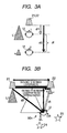
- Figs. 3A and 3B are diagrams illustrating a conversion procedure of a delay difference. As shown in Fig. 3A , let the volume level of the loudspeaker 21, the volume level of the loudspeaker 22, the distance from the loudspeaker 22 to the listening position 90, and the distance from the loudspeaker 21 to the listening position 90 be L1, L2, d1, and d2, respectively.
- a listening displacement ⁇ is determined, and the distances d1 and d2 are geometrically expressed by the following expressions.
- the controller 17 reads out the distance between the loudspeakers 21 and 22 and the listening distance H from the memory 18, determines ⁇ (> 0) by Expressions 1 to 3, and calculates d1 and d2. Then, a distance difference df between d1 and d2 is calculated, and a delay difference is obtained by dividing the delay difference df by the sound velocity. The controller 17 adjusts the delay correctors 82L and 82R on the basis of the obtained delay difference.
- a timing at which sounds emitted from the two loudspeakers reach the new listening position is changed to the same as a timing at which sounds emitted from the two loudspeakers reach the default listening position. Therefore, it is possible to move the entire surround sound field in accordance with the listening position of the listener U. That is, as shown in Fig. 2G , the listener U at the new listening position 90n listens to the sounds as if the loudspeaker 22 close to the listener U from among the two loudspeakers 21 and 22 is localized as an Rch loudspeaker 22d at the same distance as the loudspeaker 21 far from the listener U.
- the Cch sound image 23 is localized at the approximately center of the Lch loudspeaker 21 and the Rch loudspeaker 22d.
- the sound V1 from the Lch loudspeaker 21 to the right ear ER of the listener U and the V2 from the Rch loudspeaker 22 (Rch loudspeaker 22d) to the right ear ER to cancel the sound V1 are in opposite phase.
- the volume level of the Lch loudspeaker 21 is L1
- the volume level of the Rch loudspeaker 22 is L2. Therefore, the listener U listens to the sounds from the loudspeakers 21 and 22 at the substantially same volume level at the listening position 90n. For this reason, at the listening position 90n, crosstalk cancellation is effectively performed, and the sounds V1 and V2 are cancelled each other. As a result, the sounds are not listened through the right ear ER of the listener U. Though not shown, the same is applied to the left ear EL of the listener U.
- the listener U turns his/her face (head) toward the center of the monitor 28 in order to view video or image displayed on the screen of the monitor 28.
- the line connecting the Lch loudspeaker 21 and the Rch loudspeaker 22d is substantially parallel to a line connecting the ears EL and ER of the listener U.
- the SLch and SRch virtual sound sources 24 and 25 are localized at rear-left and rear-right positions of the listener U where the line connecting the virtual sound sources 24 and 25 is substantially parallel to the line connecting the Lch loudspeaker 21 and the Rch loudspeaker 22d.
- the sound sources and the virtual sound sources may be localized around the listener U, and as a result, the listener U can feel the surround sense.
- Figs. 4A to 4C show a measurement result when a listening position is set at a center of two loudspeakers.
- Figs. 5A to 5C show a measurement result when a listening position is moved toward a right loudspeaker before a listening position is corrected.
- Figs. 6A to 6C show a measurement result when a listening position is moved toward a right loudspeaker after a listening position is corrected.
- Figs. 4A , 5A , and 6A show the relationship between two loudspeakers and a listening position
- Figs. 4B , 5B , and 6B show frequency characteristic diagrams of an Lch loudspeaker
- FIGS. 4C , 5C , and 6C are frequency characteristic diagrams of an Rch loudspeaker. In these drawings, frequency characteristics of a frequency band of 20 Hz to 20 kHz are shown. The frequency characteristics shown in Figs. 4A to 6C are collected by a dummy head. In the localization apparatus 1, head related transfer functions corresponding to a head shape different from the dummy head used for sound collection.
- crosstalk cancellation is effectively performed if a level difference between a direct path and an indirect path is 6 dB. Therefore, it can be seen that crosstalk cancellation is favorably performed.
- crosstalk cancellation is 6 dB or less even in a frequency band of 300 Hz or more. Therefore, it can be seen that crosstalk cancellation is not favorably performed.
- the head related transfer functions used in the SLch localization adder 42 and the SRch localization adder 46 the head related transfer functions corresponding to a head shape different from the dummy head used for sound collection.
- the volume level and the delay amount are corrected, without correcting the frequency characteristics of sounds emitted from the two loudspeakers 21 and 22, as shown in Figs. 6A to 6C , crosstalk cancellation can be favorably performed.
- Fig. 7A is a block diagram showing the structure of a localization apparatus in which delay correctors are provided at positions different from those in the localization apparatus of Fig. 1 .
- Fig. 7B is a diagram illustrating a virtual surround effect.
- Fig. 8A a block diagram showing the structure of a localization apparatus in which delay correctors are provided at positions different from those in the localization apparatus of Fig. 1 or 7A .
- Fig. 8B is a diagram illustrating a virtual surround effect.
- delay correctors 82L and 82R are provided between the adders 72 and 73 and the adders 74 and 75, respectively, at the rear of the adders 74 and 75.
- Other parts are the same as those in the localization apparatus 1. For this reason, a description will be provided focusing on a difference.
- the delay corrector 82L and 82R are provided at the rear of the crosstalk cancellation corrector 60.
- the audio signals of the rear channels are subjected to crosstalk cancellation by the crosstalk cancellation corrector 60, delayed, and are then added to different audio signals. Therefore, the audio signals of all the channels are balance-adjusted.
- the listener U turns his/her face toward the center of the monitor 28 in order to view video or image displayed on the screen of the monitor 28. For this reason, if the listener U changes the listening position, and as described with reference to Figs.
- a timing at which sounds emitted from the two loudspeakers reach the new listening position is changed to the same as a timing at which sounds emitted from the two loudspeakers reach the default listening position. That is, as shown in Fig. 7B , as described with reference to Figs. 2A to 2H , the listener U at the listening position 90n listens to SLch and SRch sounds as if they are emitted from the Lch loudspeaker 21 and an Rch loudspeaker 22d indicated by a dotted line in Fig. 7B .
- the localized positions of the SLch and SRch virtual sound sources 24 and 25 are corrected and virtually localized at the rear-left and rear-right positions of the listener U, similarly to virtual sound source localization shown in Fig. 2G .
- the two loudspeakers 21 and 22 become the Lch and Rch sound sources, and thus the Cch sound image 23 is localized at the approximately center of the two loudspeakers 21 and 22.
- the sound sources of the rear channels subject to crosstalk cancellation can be virtually localized, and the sound sources of other channels not subject to crosstalk cancellation can be localized at the two loudspeakers or the center of the two loudspeakers. Therefore, the sound sources of channels other than the rear channels can be localized on the monitor 28 or a near side of the monitor 28, not on a depth side of the monitor 28.
- a localization apparatus 3 shown in Fig. 8A is different from the localization apparatus 2 in that delay correctors 83L and 83R are provided on Lch and Rch input signal lines 76 and 77 in front of the adders 74 and 75, respectively.
- Other parts are the same as those in the localization apparatus 2. For this reason, a description will be provided focusing on a difference.
- the delay correctors 82L, 82R, 83L, and 83R are provided at the rear of the crosstalk cancellation corrector 60 and on the Lch and Rch input signal lines 76 and 77 in front of the adders 74 and 75, respectively.
- the controller 17 calculates the distance difference df between the two loudspeakers according to the procedure described with reference to Figs. 3A and 3B , and also obtains the delay difference.
- the delay correctors 82L and 82R and the delay correctors 83L and 83R are adjusted on the basis of the obtained delay difference.
- the audio signals of the rear channels are subjected to crosstalk cancellation by the crosstalk cancellation corrector 60 and the audio signals of the front channels are delayed, and are then added to other audio signals. Therefore, the audio signals of all the channels are balance-adjusted.
- the listener U turns his/her face toward to the center of the monitor 28 in order to view video or image displayed on the screen of the monitor 28. For this reason, if the listener changes the listening position, and as described with reference to Figs. 2A to 2H , correction is performed, a timing at which sounds emitted from the two loudspeakers reach the new listening position is changed to the same as a timing at which sounds emitted from the two loudspeakers reach the default listening position. That is, as shown in Fig.
- the listener U at the listening position 90n listens to sounds as if the loudspeaker 22 close to the listener U from among the two loudspeakers 21 and 22 is localized as the Rch loudspeaker 22d, indicated by the dotted line, at the same distance as the loudspeaker 21 far from the listener U.
- the Cch sound image 23 is not delayed, and thus it is localized at the approximately center of the Lch loudspeaker 21 and the Rch loudspeaker 22.
- the SLch and SRch virtual sound sources 24 and 25 are localized at rear-left and rear-right positions of the listener U where a line connecting the virtual sound sources 24 and 25 is substantially parallel to a line connecting the Lch loudspeaker 21 and the Rch virtual loudspeaker 22d. Therefore, at the listening position 90n, the listener U can feel the surround sense.
- the sound sources of the rear channels subject to crosstalk cancellation are virtually localized, and delay is performed as if the Rch virtual loudspeaker 22d is localized on a depth side of the Rch loudspeaker 22. Therefore, the audio signals of the channels other than the center channel are delayed and balance-adjusted, and thus the entire sound field excluding the center channel can be moved in accordance with the listening position.
- the sound source of the center channel can be localized on the monitor 28 or a near side of the monitor 28, not on a depth side of the monitor 28.
- a change in position of the delay correctors enables selection of a localization position of a sound source to be corrected for any of the multi-channel sound.
- the delay correctors 81L, 81R, 82L, 82R, 83L, and 83R may be provided in a single localization apparatus, and the listener U may operate the operating section 19 to selectively function the same delay correctors as those in one of the localization apparatuses 1 to 3. In this case, the localization of the sound sources may be changed in accordance with the preference of the listener U.
- the distance D between the loudspeakers 21 and 22 is substantially identical to the horizontal width of the monitor 28, which is provided along with one of the localization apparatuses 1 to 3, and the listening distance H is determined by the optimum viewing distance of the monitor 28 (the shortest distance between the line connecting the two loudspeakers and the listening position).
- the monitor size in the case of the system having one of the localization apparatuses 1 to 3 and the monitor 28, the monitor size (inches), the horizontal width of the monitor, and the optimum viewing distance of the monitor may be stored in the memory 18 beforehand in association with each other. When such a system is installed, the monitor size may be input by using the operating section 19.
- the controller 17 can read out the horizontal width of the monitor as the distance D between the loudspeakers 21 and 22 and the optimum viewing distance of the monitor as the listening distance H from the memory 18, and can perform the above-described adjustment.
- a position detection unit for detecting the position of the listener or a plurality of sound image localization coefficients are not needed.
- the correction of the levels (balance) of the audio signals and the delay amount in accordance with the listening position of the listener ensures adjustment of the localized positions of the virtual sound sources, without needing correction of frequency characteristics in accordance with an angle of the listening position with respect to the two loudspeakers. As a result, the listener can feel the surround sense.
- SLch and SRch are localized as the virtual sound sources
- the invention is not limited thereto.
- other channels such as Lch, Rch, and the like, may be localized as the virtual sound sources.
- a sound image, which is desired at a center for example, a sound image, such as a voice of an announcer in a news program or a vocalist of a band, may be localized at the approximately center of the two loudspeakers 21 and 22.
Landscapes
- Physics & Mathematics (AREA)
- Engineering & Computer Science (AREA)
- Acoustics & Sound (AREA)
- Signal Processing (AREA)
- Stereophonic System (AREA)
Claims (5)
- Vorrichtung (1, 2, 3) zur Lokalisierung einer virtuellen Klangquelle, in der zwei Lautsprecher (21, 22) zum Emittieren von Klang von Video-/Klanginhalt an vorderen linken und vorderen rechten Positionen hinsichtlich einer Standardhörposition angeordnet sind, und Mehrkanal-Audiosignale des Video-/Klanginhalts an die zwei Lautsprecher geliefert werden, um dadurch virtuelle Klangquellen (24, 25) um einen Zuhörer (U) an der Standardhörposition (90) zu lokalisieren, weil die Vorrichtung umfasst:eine virtuelle Lokalisation-Vermittlungseinheit (42, 46), die eingerichtet ist zum Berechnen von Transfercharakteristiken von Klang, der Ohren des Zuhörers an der Standardhörposition von einer virtuell lokalisierten Position um die Standardhörposition erreicht, auf Basis von vorbestimmten kopfbezogenen Transferfunktionen, und zum Vermitteln der Transfercharakteristiken zu Audiosignalen der Kanäle, die als virtuelle Klangquelle zu lokalisieren sind;eine Übersprechen-Aufhebungseinheit (60), die eingerichtet ist zum Durchführen einer Übersprechensaufhebung auf den Audiosignalen, die mit den Transfercharakteristiken ausgestattet sind, um ein Übersprechen für den Zuhörer an der Standardhörposition aufzuheben;eine Handlungseinheit (17), die eingerichtet ist zum Empfangen einer Handlung von dem Zuhörer, um ein Klangbild (23) zu lokalisieren, von dem gewünscht wird, an einem ungefähren Mittelpunkt der zwei Lautsprecher an einer neuen Hörposition (90n) verschieden von der Standardhörposition (90) lokalisiert zu werden;eine Balance-Anpassungseinheit (84), die eingerichtet ist zum Durchführen einer Balanceanpassung auf den Signalpegeln der Audiosignale, die an die zwei Lautsprecher zu liefern sind, in Übereinstimmung mit der von der Handlungseinheit empfangenen Handlung, um Klang des von den zwei Lautsprechern emittierten Klangbildes einzustellen, an dem gleichen Lautstärkepegel an der neuen Hörposition zu sein;eine erste Verzögerungseinheit (81, 82, 83), die eingerichtet ist zum Berechnen einer Differenz in einer Distanz von den zwei Lautsprechern zu der neuen Hörposition (90n) in Verbindung mit der von der Balance-Anpassungseinheit (84) durchgeführten Balanceanpassung, zum Verzögern einer Zeitsteuerung zum Liefern der der Übersprechensaufhebung unterworfenen Audiosignale an die zwei Lautsprecher (21, 22) auf Basis der Differenz in der Distanz, um eine Zeitsteuerung zu ändern, zu der von den zwei Lautsprechern (21, 22) emittierten Klänge die neue Hörposition (90n) erreichen, auf die gleiche wie eine Zeitsteuerung, an der von den zwei Lautsprechern emittierten Klänge die Standardhörposition (90) erreichen, und zum Ausgeben der verzögerten Audiosignale an die Balance-Anpassungseinheit (84);eine Eingabeeinheit (19), die eingerichtet ist zum Empfangen, als Daten, die zum Berechnen der Differenz in einer Distanz von den zwei Lautsprechern zu der neuen Hörposition zu verwenden sind, einer Eingabe einer Information betreffend eine Distanz zwischen den zwei Lautsprechern und einer kürzesten Distanz zwischen einer die zwei Lautsprecher verbindenden Linie und der Hörposition; undeine Speichereinheit (18), die eingerichtet ist zum Speichern der von der Eingabeeinheit empfangenen Information,wobei die erste Verzögerungseinheit (81, 82, 83) eingerichtet ist zum Berechnen der Differenz in einer Distanz durch Verwenden der von der Speichereinheit ausgelesen Information und einer Differenz in Ausgangspegeln zwischen den zwei Lautsprechern, nachdem die Balanceanpassung von der Balance-Anpassungseinheit durchgeführt wurde.
- Vorrichtung nach Anspruch 1, weiterhin umfassend:eine Addiereinheit (74, 75), die eingerichtet ist zum Addieren des der Übersprechensaufhebung unterworfenen Audiosignals und eines anderen, nicht der Übersprechensaufhebung unterworfenen Audiosignals, für jedes der Mehrkanal-Audiosignale,wobei die erste Verzögerungseinheit (81, 82, 83) eingerichtet ist zum Verzögern des addierten Audiosignals.
- Vorrichtung nach Anspruch 1, weiterhin umfassend:eine Addiereinheit (74, 75), die eingerichtet ist zum Addieren des der Übersprechensaufhebung unterworfenen Audiosignals und eines anderen, nicht der Übersprechensaufhebung unterworfenen Audiosignals für jedes der Mehrkanal-Audiosignale,wobei die Balance-Anpassungseinheit (84) eingerichtet ist zum Durchführen der Balanceanpassung auf den von dem Addiereinheit addierten Audiosignal.
- Vorrichtung nach Anspruch 3,
wobei das andere, nicht der Übersprechensaufhebung unterworfene Audiosignal ein Vorderkanal-Audiosignal enthält, und
die Vorrichtung weiterhin enthält:eine zweite Verzögerungseinheit (83), die eingerichtet ist zum Verzögern einer Klangausgabezeitsteuerung zum Liefern der Vorderkanal-Audiosignalen an die zwei Lautsprecher auf Basis der Differenz in einer Distanz, die von der Verzögerungseinheit berechnet wird, um Klang basierend auf den Vorderkanal-Audiosignalen zu veranlassen, von den virtuell lokalisierten zwei Lautsprechern emittiert zu werden. - Vorrichtung nach Anspruch 1, weiterhin umfassend:einen Monitor (28) zum Anzeigen von Video des Video-/Klanginhalts, angeordnet zwischen den zwei Lautsprechern;eine Größenspeichereinheit (18), die eingerichtet ist zum Speichern einer Größe des Monitors, einer Distanz zwischen den zwei Lautsprechern, eingestellt entsprechend der Größe, und einer kürzesten Distanz zwischen einer die zwei Lautsprecher verbindenden Linie und der Hörposition; undeine Größeneingabeeinheit (19), die eingerichtet ist zum Empfangen einer Eingabe der Größe des Monitors,wobei die Verzögerungseinheit (81, 82, 83), die eingerichtet ist zum Auslesen von Information betreffend die Distanz zwischen den Lautsprechern gemäß der Größe des Monitors, empfangen von der Größeneingabeeinheit, und der kürzesten Distanz zwischen der die zwei Lautsprecher verbindenden Linie und der Hörposition von der Größenspeichereinheit, und zum Berechnen der Differenz in einer Distanz durch Verwenden der Information und einer Differenz in Ausgabepegel zwischen den zwei Lautsprechern, nachdem die Balanceanpassung von der Balance-Anpassungseinheit durchgeführt wurde.
Applications Claiming Priority (1)
| Application Number | Priority Date | Filing Date | Title |
|---|---|---|---|
| JP2007295637A JP5245368B2 (ja) | 2007-11-14 | 2007-11-14 | 仮想音源定位装置 |
Publications (3)
| Publication Number | Publication Date |
|---|---|
| EP2061279A2 EP2061279A2 (de) | 2009-05-20 |
| EP2061279A3 EP2061279A3 (de) | 2013-03-27 |
| EP2061279B1 true EP2061279B1 (de) | 2015-09-09 |
Family
ID=40343553
Family Applications (1)
| Application Number | Title | Priority Date | Filing Date |
|---|---|---|---|
| EP08169126.3A Ceased EP2061279B1 (de) | 2007-11-14 | 2008-11-14 | Vorrichtung zur Lokalisierung einer virtuellen Klangquelle |
Country Status (3)
| Country | Link |
|---|---|
| US (1) | US8494189B2 (de) |
| EP (1) | EP2061279B1 (de) |
| JP (1) | JP5245368B2 (de) |
Families Citing this family (45)
| Publication number | Priority date | Publication date | Assignee | Title |
|---|---|---|---|---|
| JP4946305B2 (ja) * | 2006-09-22 | 2012-06-06 | ソニー株式会社 | 音響再生システム、音響再生装置および音響再生方法 |
| WO2010140088A1 (en) * | 2009-06-03 | 2010-12-09 | Koninklijke Philips Electronics N.V. | Estimation of loudspeaker positions |
| JP2011049785A (ja) * | 2009-08-26 | 2011-03-10 | Sharp Corp | 音声信号処理装置、音声信号処理方法、および表示装置 |
| EP2309781A3 (de) * | 2009-09-23 | 2013-12-18 | Iosono GmbH | Vorrichtung und Verfahren zur Berechnung der Filterkoeffizienten für vordefinierte Lautsprecheranordnung |
| JP5330328B2 (ja) * | 2010-08-04 | 2013-10-30 | 株式会社東芝 | 音像定位装置 |
| WO2012147196A1 (ja) * | 2011-04-28 | 2012-11-01 | パイオニア株式会社 | 音声信号処理装置及び音声信号処理プログラム |
| US10321252B2 (en) * | 2012-02-13 | 2019-06-11 | Axd Technologies, Llc | Transaural synthesis method for sound spatialization |
| US8704070B2 (en) * | 2012-03-04 | 2014-04-22 | John Beaty | System and method for mapping and displaying audio source locations |
| US9462384B2 (en) | 2012-09-05 | 2016-10-04 | Harman International Industries, Inc. | Nomadic device for controlling one or more portable speakers |
| US20150264502A1 (en) * | 2012-11-16 | 2015-09-17 | Yamaha Corporation | Audio Signal Processing Device, Position Information Acquisition Device, and Audio Signal Processing System |
| US11395086B2 (en) * | 2013-03-15 | 2022-07-19 | Jawbone Innovations, Llc | Listening optimization for cross-talk cancelled audio |
| US10827292B2 (en) | 2013-03-15 | 2020-11-03 | Jawb Acquisition Llc | Spatial audio aggregation for multiple sources of spatial audio |
| KR102127640B1 (ko) * | 2013-03-28 | 2020-06-30 | 삼성전자주식회사 | 휴대 단말 및 보청기와 휴대 단말에서 음원의 위치를 제공하는 방법 |
| JP6369465B2 (ja) * | 2013-07-24 | 2018-08-08 | ソニー株式会社 | 情報処理装置および方法、並びにプログラム |
| JP6287202B2 (ja) * | 2013-08-19 | 2018-03-07 | ヤマハ株式会社 | スピーカ装置 |
| US9042563B1 (en) | 2014-04-11 | 2015-05-26 | John Beaty | System and method to localize sound and provide real-time world coordinates with communication |
| CN104125522A (zh) * | 2014-07-18 | 2014-10-29 | 北京智谷睿拓技术服务有限公司 | 声道配置方法、装置及用户设备 |
| US9544679B2 (en) * | 2014-12-08 | 2017-01-10 | Harman International Industries, Inc. | Adjusting speakers using facial recognition |
| JP2016140039A (ja) * | 2015-01-29 | 2016-08-04 | ソニー株式会社 | 音響信号処理装置、音響信号処理方法、及び、プログラム |
| US20170078793A1 (en) * | 2015-03-23 | 2017-03-16 | Eric Jay Alexander | Inversion Speaker and Headphone for Music Production |
| KR102342081B1 (ko) * | 2015-04-22 | 2021-12-23 | 삼성디스플레이 주식회사 | 멀티미디어 장치 및 이의 구동 방법 |
| US20160321917A1 (en) * | 2015-04-30 | 2016-11-03 | Board Of Regents, The University Of Texas System | Utilizing a mobile device as a motion-based controller |
| US9686625B2 (en) * | 2015-07-21 | 2017-06-20 | Disney Enterprises, Inc. | Systems and methods for delivery of personalized audio |
| WO2017098949A1 (ja) * | 2015-12-10 | 2017-06-15 | ソニー株式会社 | 音声処理装置および方法、並びにプログラム |
| DE102016103209A1 (de) | 2016-02-24 | 2017-08-24 | Visteon Global Technologies, Inc. | System und Verfahren zur Positionserkennung von Lautsprechern und zur Wiedergabe von Audiosignalen als Raumklang |
| CN106028226B (zh) * | 2016-05-27 | 2019-03-05 | 北京奇虎科技有限公司 | 声音播放方法及设备 |
| US10205906B2 (en) | 2016-07-26 | 2019-02-12 | The Directv Group, Inc. | Method and apparatus to present multiple audio content |
| CN110892735B (zh) * | 2017-07-31 | 2021-03-23 | 华为技术有限公司 | 一种音频处理方法以及音频处理设备 |
| US11477595B2 (en) | 2018-04-10 | 2022-10-18 | Sony Corporation | Audio processing device and audio processing method |
| JP2020036113A (ja) * | 2018-08-28 | 2020-03-05 | シャープ株式会社 | 音響システム |
| KR102174168B1 (ko) | 2018-10-26 | 2020-11-04 | 주식회사 에스큐그리고 | 스피커 음향 특성을 고려한 독립음장 구현 방법 및 구현 시스템 |
| CN109639881A (zh) * | 2018-11-10 | 2019-04-16 | 东莞市华睿电子科技有限公司 | 一种通话中音频信号的播放控制方法 |
| CN109672916B (zh) * | 2018-12-29 | 2022-03-11 | 深圳Tcl新技术有限公司 | 信源的切换方法、电视机及存储介质 |
| WO2021138421A1 (en) * | 2019-12-31 | 2021-07-08 | Harman International Industries, Incorporated | System and method for virtual sound effect with invisible loudspeaker(s) |
| CN111372167B (zh) * | 2020-02-24 | 2021-10-26 | Oppo广东移动通信有限公司 | 音效优化方法及装置、电子设备、存储介质 |
| US10945090B1 (en) * | 2020-03-24 | 2021-03-09 | Apple Inc. | Surround sound rendering based on room acoustics |
| CN112135226B (zh) * | 2020-08-11 | 2022-06-10 | 广东声音科技有限公司 | Y轴音频再生方法以及y轴音频再生系统 |
| CN114747196B (zh) * | 2020-08-21 | 2025-07-29 | Lg电子株式会社 | 使用多个音频装置来输出多声道音频的终端和方法 |
| EP4288879A4 (de) | 2021-02-05 | 2024-12-11 | Sound United LLC | System und verfahren zur bereitstellung von erweitertem audio für streaming-videoinhalt |
| US12483852B1 (en) * | 2021-09-20 | 2025-11-25 | Sound United Llc | System and method for adjusting loudspeaker performance based on listener location |
| WO2023061972A1 (en) * | 2021-10-11 | 2023-04-20 | Telefonaktiebolaget Lm Ericsson (Publ) | Spatial rendering of audio elements having an extent |
| CN113993057A (zh) * | 2021-10-25 | 2022-01-28 | 浙江德清知路导航科技有限公司 | 基于音频实时定位技术的声场自适应系统、方法、存储介质 |
| US12470872B2 (en) | 2022-01-31 | 2025-11-11 | Sound United, LLC | Loudspeaker systems |
| US12610205B2 (en) * | 2022-12-09 | 2026-04-21 | Bang & Olufsen A/S | Adaptive loudspeaker and listener positioning compensation |
| CN117729472B (zh) * | 2024-01-31 | 2024-09-27 | 深圳市丰禾原电子科技有限公司 | 家庭影院系统的音效设置方法、装置和计算机存储介质 |
Citations (2)
| Publication number | Priority date | Publication date | Assignee | Title |
|---|---|---|---|---|
| JPS62140600A (ja) * | 1985-12-13 | 1987-06-24 | Matsushita Electric Ind Co Ltd | 音響効果装置 |
| JPH02140100A (ja) * | 1988-08-30 | 1990-05-29 | Nec Corp | オーディオ信号処理システム |
Family Cites Families (14)
| Publication number | Priority date | Publication date | Assignee | Title |
|---|---|---|---|---|
| JPS57141500U (de) * | 1981-02-26 | 1982-09-04 | ||
| EP0357034A3 (de) * | 1988-08-30 | 1991-08-07 | Nec Corporation | Audioverarbeitungssystem für Balancesteuerung der Amplitude und Phase eines Audiosignals |
| JP2985919B2 (ja) | 1993-02-26 | 1999-12-06 | 日本ビクター株式会社 | 音像定位制御装置 |
| JPH08265899A (ja) * | 1995-01-26 | 1996-10-11 | Victor Co Of Japan Ltd | サラウンド信号処理装置及び映像音声再生装置 |
| US5799094A (en) * | 1995-01-26 | 1998-08-25 | Victor Company Of Japan, Ltd. | Surround signal processing apparatus and video and audio signal reproducing apparatus |
| JPH09252499A (ja) * | 1996-03-14 | 1997-09-22 | Mitsubishi Electric Corp | 多チャンネル音響再生装置 |
| US6850621B2 (en) * | 1996-06-21 | 2005-02-01 | Yamaha Corporation | Three-dimensional sound reproducing apparatus and a three-dimensional sound reproduction method |
| US6243476B1 (en) * | 1997-06-18 | 2001-06-05 | Massachusetts Institute Of Technology | Method and apparatus for producing binaural audio for a moving listener |
| US7113609B1 (en) * | 1999-06-04 | 2006-09-26 | Zoran Corporation | Virtual multichannel speaker system |
| US8054980B2 (en) * | 2003-09-05 | 2011-11-08 | Stmicroelectronics Asia Pacific Pte, Ltd. | Apparatus and method for rendering audio information to virtualize speakers in an audio system |
| KR101118214B1 (ko) | 2004-09-21 | 2012-03-16 | 삼성전자주식회사 | 청취 위치를 고려한 2채널 가상 음향 재생 방법 및 장치 |
| JP2007028134A (ja) | 2005-07-15 | 2007-02-01 | Fujitsu Ltd | 携帯電話機 |
| JP2007028198A (ja) * | 2005-07-15 | 2007-02-01 | Yamaha Corp | 音響装置 |
| KR100739798B1 (ko) * | 2005-12-22 | 2007-07-13 | 삼성전자주식회사 | 청취 위치를 고려한 2채널 입체음향 재생 방법 및 장치 |
-
2007
- 2007-11-14 JP JP2007295637A patent/JP5245368B2/ja not_active Expired - Fee Related
-
2008
- 2008-11-14 EP EP08169126.3A patent/EP2061279B1/de not_active Ceased
- 2008-11-14 US US12/271,289 patent/US8494189B2/en active Active
Patent Citations (2)
| Publication number | Priority date | Publication date | Assignee | Title |
|---|---|---|---|---|
| JPS62140600A (ja) * | 1985-12-13 | 1987-06-24 | Matsushita Electric Ind Co Ltd | 音響効果装置 |
| JPH02140100A (ja) * | 1988-08-30 | 1990-05-29 | Nec Corp | オーディオ信号処理システム |
Also Published As
| Publication number | Publication date |
|---|---|
| US20090123007A1 (en) | 2009-05-14 |
| JP2009124395A (ja) | 2009-06-04 |
| JP5245368B2 (ja) | 2013-07-24 |
| EP2061279A3 (de) | 2013-03-27 |
| US8494189B2 (en) | 2013-07-23 |
| EP2061279A2 (de) | 2009-05-20 |
Similar Documents
| Publication | Publication Date | Title |
|---|---|---|
| US8494189B2 (en) | Virtual sound source localization apparatus | |
| US9432793B2 (en) | Head-related transfer function convolution method and head-related transfer function convolution device | |
| KR100678929B1 (ko) | 다채널 디지털 사운드 재생방법 및 장치 | |
| EP2664165B1 (de) | Vorrichtungen, systeme und verfahren für steuerbare schallbereiche in einem medienraum | |
| JP4924119B2 (ja) | アレイスピーカ装置 | |
| CN1658709B (zh) | 声音再现设备和声音再现方法 | |
| JP7785664B2 (ja) | ハイブリッド式近距離/遠距離場スピーカー仮想化 | |
| CN101931853A (zh) | 音频信号处理设备和音频信号处理方法 | |
| EP3214854B1 (de) | Lautsprechervorrichtung | |
| US7978860B2 (en) | Playback apparatus and playback method | |
| JP4867367B2 (ja) | 立体音響再生装置 | |
| JP2012235456A (ja) | 音声信号処理装置及び音声信号処理プログラム | |
| JP2008312096A (ja) | 音響再生装置及びテレビ受像機 | |
| JP4466519B2 (ja) | Avアンプ装置 | |
| JP5194614B2 (ja) | 音場形成装置 | |
| JP6287191B2 (ja) | スピーカ装置 | |
| JP5326332B2 (ja) | スピーカ装置、信号処理方法およびプログラム | |
| JP4917946B2 (ja) | 音像定位処理装置等 | |
| JP2023080769A (ja) | 再生制御装置、頭外定位処理システム、及び再生制御方法 | |
| JP2011004261A (ja) | Avアンプ装置 | |
| JP4848774B2 (ja) | 音響装置、音響再生方法および音響再生プログラム | |
| JP4981995B1 (ja) | 音声信号処理装置及び音声信号処理プログラム | |
| JP2006352728A (ja) | オーディオ装置 | |
| JP2009212944A (ja) | 音響装置 | |
| JP2015126358A (ja) | スピーカ装置 |
Legal Events
| Date | Code | Title | Description |
|---|---|---|---|
| PUAI | Public reference made under article 153(3) epc to a published international application that has entered the european phase |
Free format text: ORIGINAL CODE: 0009012 |
|
| AK | Designated contracting states |
Kind code of ref document: A2 Designated state(s): AT BE BG CH CY CZ DE DK EE ES FI FR GB GR HR HU IE IS IT LI LT LU LV MC MT NL NO PL PT RO SE SI SK TR |
|
| AX | Request for extension of the european patent |
Extension state: AL BA MK RS |
|
| PUAL | Search report despatched |
Free format text: ORIGINAL CODE: 0009013 |
|
| AK | Designated contracting states |
Kind code of ref document: A3 Designated state(s): AT BE BG CH CY CZ DE DK EE ES FI FR GB GR HR HU IE IS IT LI LT LU LV MC MT NL NO PL PT RO SE SI SK TR |
|
| AX | Request for extension of the european patent |
Extension state: AL BA MK RS |
|
| RIC1 | Information provided on ipc code assigned before grant |
Ipc: H04S 7/00 20060101AFI20130218BHEP |
|
| 17P | Request for examination filed |
Effective date: 20130917 |
|
| RBV | Designated contracting states (corrected) |
Designated state(s): AT BE BG CH CY CZ DE DK EE ES FI FR GB GR HR HU IE IS IT LI LT LU LV MC MT NL NO PL PT RO SE SI SK TR |
|
| AKX | Designation fees paid |
Designated state(s): DE FR GB |
|
| 17Q | First examination report despatched |
Effective date: 20140103 |
|
| GRAP | Despatch of communication of intention to grant a patent |
Free format text: ORIGINAL CODE: EPIDOSNIGR1 |
|
| INTG | Intention to grant announced |
Effective date: 20150402 |
|
| GRAS | Grant fee paid |
Free format text: ORIGINAL CODE: EPIDOSNIGR3 |
|
| GRAA | (expected) grant |
Free format text: ORIGINAL CODE: 0009210 |
|
| AK | Designated contracting states |
Kind code of ref document: B1 Designated state(s): DE FR GB |
|
| REG | Reference to a national code |
Ref country code: GB Ref legal event code: FG4D |
|
| REG | Reference to a national code |
Ref country code: FR Ref legal event code: PLFP Year of fee payment: 8 |
|
| REG | Reference to a national code |
Ref country code: DE Ref legal event code: R096 Ref document number: 602008040049 Country of ref document: DE |
|
| REG | Reference to a national code |
Ref country code: DE Ref legal event code: R097 Ref document number: 602008040049 Country of ref document: DE |
|
| PLBE | No opposition filed within time limit |
Free format text: ORIGINAL CODE: 0009261 |
|
| STAA | Information on the status of an ep patent application or granted ep patent |
Free format text: STATUS: NO OPPOSITION FILED WITHIN TIME LIMIT |
|
| 26N | No opposition filed |
Effective date: 20160610 |
|
| REG | Reference to a national code |
Ref country code: FR Ref legal event code: PLFP Year of fee payment: 9 |
|
| REG | Reference to a national code |
Ref country code: FR Ref legal event code: PLFP Year of fee payment: 10 |
|
| PGFP | Annual fee paid to national office [announced via postgrant information from national office to epo] |
Ref country code: DE Payment date: 20171108 Year of fee payment: 10 Ref country code: FR Payment date: 20171012 Year of fee payment: 10 |
|
| PGFP | Annual fee paid to national office [announced via postgrant information from national office to epo] |
Ref country code: GB Payment date: 20171108 Year of fee payment: 10 |
|
| REG | Reference to a national code |
Ref country code: DE Ref legal event code: R119 Ref document number: 602008040049 Country of ref document: DE |
|
| GBPC | Gb: european patent ceased through non-payment of renewal fee |
Effective date: 20181114 |
|
| PG25 | Lapsed in a contracting state [announced via postgrant information from national office to epo] |
Ref country code: DE Free format text: LAPSE BECAUSE OF NON-PAYMENT OF DUE FEES Effective date: 20190601 Ref country code: FR Free format text: LAPSE BECAUSE OF NON-PAYMENT OF DUE FEES Effective date: 20181130 |
|
| PG25 | Lapsed in a contracting state [announced via postgrant information from national office to epo] |
Ref country code: GB Free format text: LAPSE BECAUSE OF NON-PAYMENT OF DUE FEES Effective date: 20181114 |