EP2062018B1 - Retardateur sensiblement achromatique à compensation autonome de l'angle de déviation - Google Patents
Retardateur sensiblement achromatique à compensation autonome de l'angle de déviation Download PDFInfo
- Publication number
- EP2062018B1 EP2062018B1 EP07810297A EP07810297A EP2062018B1 EP 2062018 B1 EP2062018 B1 EP 2062018B1 EP 07810297 A EP07810297 A EP 07810297A EP 07810297 A EP07810297 A EP 07810297A EP 2062018 B1 EP2062018 B1 EP 2062018B1
- Authority
- EP
- European Patent Office
- Prior art keywords
- right angle
- sides
- parallelogram shaped
- rhomb
- another
- Prior art date
- Legal status (The legal status is an assumption and is not a legal conclusion. Google has not performed a legal analysis and makes no representation as to the accuracy of the status listed.)
- Active
Links
- GDOPTJXRTPNYNR-UHFFFAOYSA-N CC1CCCC1 Chemical compound CC1CCCC1 GDOPTJXRTPNYNR-UHFFFAOYSA-N 0.000 description 1
Images


Classifications
-
- G—PHYSICS
- G02—OPTICS
- G02B—OPTICAL ELEMENTS, SYSTEMS OR APPARATUS
- G02B5/00—Optical elements other than lenses
- G02B5/30—Polarising elements
-
- G—PHYSICS
- G02—OPTICS
- G02B—OPTICAL ELEMENTS, SYSTEMS OR APPARATUS
- G02B5/00—Optical elements other than lenses
- G02B5/30—Polarising elements
- G02B5/3083—Birefringent or phase retarding elements
-
- G—PHYSICS
- G01—MEASURING; TESTING
- G01J—MEASUREMENT OF INTENSITY, VELOCITY, SPECTRAL CONTENT, POLARISATION, PHASE OR PULSE CHARACTERISTICS OF INFRARED, VISIBLE OR ULTRAVIOLET LIGHT; COLORIMETRY; RADIATION PYROMETRY
- G01J4/00—Measuring polarisation of light
-
- G—PHYSICS
- G01—MEASURING; TESTING
- G01N—INVESTIGATING OR ANALYSING MATERIALS BY DETERMINING THEIR CHEMICAL OR PHYSICAL PROPERTIES
- G01N21/00—Investigating or analysing materials by the use of optical means, i.e. using sub-millimetre waves, infrared, visible or ultraviolet light
- G01N21/17—Systems in which incident light is modified in accordance with the properties of the material investigated
- G01N21/21—Polarisation-affecting properties
- G01N21/211—Ellipsometry
-
- G—PHYSICS
- G02—OPTICS
- G02B—OPTICAL ELEMENTS, SYSTEMS OR APPARATUS
- G02B26/00—Optical devices or arrangements for the control of light using movable or deformable optical elements
- G02B26/06—Optical devices or arrangements for the control of light using movable or deformable optical elements for controlling the phase of light
-
- G—PHYSICS
- G02—OPTICS
- G02B—OPTICAL ELEMENTS, SYSTEMS OR APPARATUS
- G02B27/00—Optical systems or apparatus not provided for by any of the groups G02B1/00 - G02B26/00, G02B30/00
- G02B27/28—Optical systems or apparatus not provided for by any of the groups G02B1/00 - G02B26/00, G02B30/00 for polarising
-
- G—PHYSICS
- G01—MEASURING; TESTING
- G01J—MEASUREMENT OF INTENSITY, VELOCITY, SPECTRAL CONTENT, POLARISATION, PHASE OR PULSE CHARACTERISTICS OF INFRARED, VISIBLE OR ULTRAVIOLET LIGHT; COLORIMETRY; RADIATION PYROMETRY
- G01J1/00—Photometry, e.g. photographic exposure meter
- G01J1/02—Details
- G01J1/04—Optical or mechanical part supplementary adjustable parts
- G01J1/0407—Optical elements not provided otherwise, e.g. manifolds, windows, holograms, gratings
-
- G—PHYSICS
- G01—MEASURING; TESTING
- G01N—INVESTIGATING OR ANALYSING MATERIALS BY DETERMINING THEIR CHEMICAL OR PHYSICAL PROPERTIES
- G01N21/00—Investigating or analysing materials by the use of optical means, i.e. using sub-millimetre waves, infrared, visible or ultraviolet light
- G01N21/17—Systems in which incident light is modified in accordance with the properties of the material investigated
- G01N21/21—Polarisation-affecting properties
- G01N21/211—Ellipsometry
- G01N2021/213—Spectrometric ellipsometry
Definitions
- the present invention relates to a system for introducing a relative phase retardation into orthogonally polarized components of an incident electromagnetic beam.
- Systems of the invention may be used to provide a substantially achromatic retarder which uses multiple total internal reflections of a single, undeviated, transmitted beam to generate retardance.
- the reflections are oriented to minimize changes in the net retardance against the input beam angle over a wide spectral range, namely, 190 - 1700 nm, as a function of system translation and rotation.
- the retarders are suitable for use in a rotating compensator ellipsometer or polarimeter.
- compensator-based ellipsometer and/or polarimeter designs require a compensator element that provides retardance within a certain acceptable range over the entire spectral range.
- birefringent waveplates of quartz or MgF 2 have been used as compensator elements in rotating element designs.
- a single waveplate exhibits a (1/wavelength) dependence in retardance vs. wavelength, while a dual/multiple waveplate design, (as disclosed in US Patent No. 6,353,477 ), can minimize the effect of the (1/wavelength) dependence.
- NAGIB N ET AL "Total internal reflection phase retarders constructed from prisms; Total internal reflection phase retarders constructed from prisms" 1 April 2004 (2004-04-01), JOURNAL OF OPTICS.
- A PURE AND APPLIED OPTICS, INSTITUTE OF PHYSICS PUBLISHING, BRISTOL, GB, PAGE(S) 425 - 425, XP020081415 ISSN: 1464-4258 , describes the construction of a rhomb-type total internal reflection phase retarder from prisms.
- US-A-6456376 describes a spectroscopic rotating compensator ellipsometer system arranged such that the electromagnetic beam intensity is caused to quickly decay to zero as a function of radius.
- D1 NAGIB N: “Phase retarders highly insensitive to the input angle” 1 March 1998 (1998-03-01), APPLIED OPTICS, OSA, OPTICAL SOCIETY OF AMERICA, WASHINGTON, DC, PAGE(S) 1231 - 1235, XP007909727 ISSN: 0003-6935 describes a retarder, for use at a specified wavelength, which is insensitive to changes in the incident angle of an input beam.
- D1 describes system for introducing a relative phase retardation into orthogonally polarized components of an electromagnetic beam entered thereinto, said system consisting of at least two sequential elements oriented with respect to one another such that said entered electromagnetic beam undergoes total internal reflection at least once in each of the at least two elements; the sequence, orientation, geometry, and symmetry of the elements being such that the locus of an output beam is substantially undeviated from the locus of the input beam; wherein two of said sequential elements are parallelogram shaped rhombs, each said rhomb having first, second, third and fourth sides, said first and third sides being parallel to one another and said second and fourth sides being parallel to one another, said first and second sides of said first parallelogram shaped rhomb, and said second and third sides of said second parallelogram shaped rhomb meeting one another at angles greater than ninety degrees therebetween, and said second and third sides of said first parallelogram shaped rhomb and said first and second sides of said second parallelogram shaped rhomb meeting one another at angles less than nine
- D1 is for use at a single wavelength
- spectral achromaticity is of secondary importance.
- the present invention seeks to provide a system for introducing a relative phase retardation into orthogonally polarized components of an incident electromagnetic beam with improved characteristics.
- a system for introducing a relative phase retardation into orthogonally polarized components of an incident electromagnetic beam as defined above is characterised in that it is for use over the spectral range of 190 to 1700 nm, in that the parallelogram shaped rhombs are each made from fused silica, in that at least one of the second and fourth sides of at least one of the parallelogram shaped rhombs has a coating thereon of MgF 2 which has a lower refractive index from that of the fused silica from which the corresponding parallelogram shaped rhomb is comprised, and in that each coating of MgF 2 is between 30-45 nm.
- angles of the parallelogram shaped rhombs are 36, 144, 36, and 144 degrees or 45, 235, 45 and 235 degrees.
- the coating of MgF 2 is 35 nm.
- one of the parallelogram shaped rhombs is formed by a combination of two sequential elements
- the other parallelogram shaped rhomb is formed by a combination of two sequential elements
- each said sequential element being a right angle prism having right angle sides adjacent to the right angle thereof and a side (ha, hc, hc, hd) opposite the right angle thereof;
- said right angle prisms being oriented with respect to one another such that, as viewed in side elevation, the first right angle prism is positioned so that its side (ha) opposite the right angle is facing downwardly and to the right, and so that directly above the first right angle prism is the second right angle prism, which is oriented so that its side (hb) opposite the right angle thereof is facing upwardly and to the left, and so that directly to the right of the second right angle prism is the third right angle prism which is oriented so that its side (hc) opposite the right angle thereof is facing upwardly and to the right, and so that directly below the third right angle prism is the fourth right
- the locus of the input beam is oriented substantially but not exactly, perpendicularly to the first side of the first parallelogram shaped rhomb.
- system further comprises at least one selection made from the group consisting of:
- the third side of the first parallelogram shaped rhomb is adjacent to the first side of the second parallelogram shaped rhomb, the said third and first sides being substantially, but not exactly, parallel and defining an acute angle therebetween.
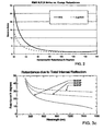
- Fig. 1 shows results from a retarder comprising two birefringent waveplates. Note that the retardance varies from 35 - 130 degrees over the typical UV-VIS-NIR spectral range of 190 - 1700 nm.
- RMS Root Mean squared
- a rotating compensator ellipsometer (RCE) configuration it has been determined to be beneficial to keep the retardance between 80 and 160 degrees, as this keeps the relative RMS N, C, S noise to less than 2.0.
- the dual-RCE configuration is slightly more forgiving over a retardance range of 60 - 160 degrees.
- Figs. 1 and 2 show that using birefringent waveplates through which a beam of electromagnetic radiation is caused to pass, in wide spectral range rotating compensator ellipsometer systems, compromises the noise performance of the system.
- Figs. 3a and 3b show retardance vs. internal angle and wavelength, (at a given angle), for a fused silica/air interface. Note that the change in retardance vs. wavelength for total internal reflectance is very small compared to the (1 /wavelength) dependence of birefringence-induced retardance. Fresnel rhomb retarders which are based on this effect are readily available.
- a typical 1/4 wave Fresnel rhomb design translates the beam significantly, and the retardance also changes significantly as a function of beam angle, making it impractical to use a Fresnel rhomb in a rotating compensator style ellipsometer or polarimeter design.
- Fig. 4a shows a Typical Wave 1/4 wave 90 degree retardance Fresnel rhomb and demonstrates the translation effect.
- Fig. 4b shows a known approach to combining two Fresnel rhombs to achieve a substantially non-translated beam.
- the rhombs each have first (RS1), second (RS2), third (RS4) and fourth (RS4) sides, with the first (RS1) and third (RS3) sides being parallel to one another, and the second (RS2) and fourth (RS4) sides being parallel to one another.
- the first (RS1) and second (RS2), and the third (RS3) and fourth (RS4) sides of the first Fresnel rhomb meet one another at angles greater than ninety degrees therebetween, and the second (RS2) and third (RS3) sides and said first (RS1) and fourth (RS4) sides thereof meet one another at angles less than ninety degrees therebetween.
- the at least two parallelogram shaped rhombs are oriented with their first (RSI) and third (RS3) sides being substantially parallel to one another.
- a beam of electromagnetic radiation caused to enter the first (RS1) side of the first Fresnel rhomb, at a substantially normal angle thereto, then proceeds so that it internally reflects from the fourth (RS4) and second (RS2) side thereof, then exits the third (RS3) side thereof in a direction such that it then enters the first (RS1) side of the second Fresnel rhomb at a substantially normal angle thereto.
- the beam then proceeds so that it internally reflects from the second (RS2) and fourth (RS4) side thereof, then exits the third (RS3) side thereof.
- the embodiment illustrated in Figure 4b is distinguished over known configurations in that at least one of the sides (RS1) (RS2) (RS3) (RS4) of at least one of the parallelogram shaped rhombs has a coating thereupon which has a different refractive index from that of the material from which the corresponding parallelogram shaped rhomb is comprised. Specifically, it is sides (RS2) and (RS4) of each rhomb which are coated.
- the angles of the parallelogram shaped rhomb can be 36, 144, 36, and 144 degrees or 45, 135, 45 and 135 degrees, and the rhombs can be fabricated from fused silica, with the coating being a material, (eg. MgF 2 ), with a lower refractive index.
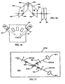
- Fig. 4c shows an embodiment of the invention which is a variation of Fig. 4b .
- four similar right angle prisms namely first (ra), second (rb), third (rc) and fourth (rd), are shown, having sides opposite their right angles of, respectively, (ha) (hb) (hc) and (hd).
- the first right angle prism (ra) is positioned so that its side (ha) opposite the right angle thereof is facing downward and to the right.
- the second right angle prism (rb) Directly above the first right angle prism (rb), which is oriented so that its side (hb) opposite the right angle thereof is facing upward and to the left.
- the third right of right angle prism (rc) which is oriented so that its side (hc) opposite the right angle thereof Is facing upward and to the right.
- the fourth right angle prism (rd) positioned directly below the third right angle prism (rd), oriented so that its side (hd) opposite the right angle thereof is facing downward and to the left.
- each element (ra) (rb) (rc) and (rd) adjacent to the right angles thereof are identifiable as "right angle sides". It is the sides of the elements (ra) (rb) (rc) and (rd) opposite to the right angles that are coated with the material of different refractive index material. As previously, where the elements are made of fused silica the coating can be, for instance, 35nm of lower index MgF 2 . The coating makes the retardance entered by a total internal reflection from a side opposite the right angle thereof substantially achromatic with range of retardation.
- Fig. 4c Also shown in Fig. 4c are two optional wedge elements (w1) and (w2), the purpose of which is described with respect to Fig. 12b .
- a coating may also be applied to a reflective outer surface thereof.
- Fig. 4d shows an embodiment of the invention having two Fresnel rhombs (R1) (R2) which are equivalent to the four right angle prisms (ra) + (rb) and (rc) + (rd) of Fig. 4c .
- Two wedges (w1) (w2) can be combined to result in a non-deviation of a beam (B) caused to pass therethrough.
- the angles of the rhombs are 45, 135, 45 and 135 degrees.
- Coatings with a different refractive index from that of the material from which the rhomb is comprised are provided on surfaces thereof as described above with reference to Fig. 4b .
- a beam (B) is typically not entered exactly along a normal to the surface entered, (eg. (RS1) in Fig. 4d ).
- This diverts unwanted depolarizing secondary bounces out of the primary beam and such a beam entry locus can be termed "substantially normal" to the surface where the off-normal angle is sufficient to divert said reflections.
- a typical off-normal angle is about three (3) degrees which deviates transmitted secondary beams by about six (6) degrees. This is sufficient to provide separation from the primary transmitted beam.
- the wedges (w1) (w2) can be rotated with respect to one another and/or simultaneously to result in a non-deviated beam, (B).
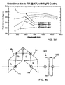
- Fig. 3c shows retardance vs. internal angle and wavelength, (at a given angle), for the fused silica/air interface for an arrangement as in Fig. 4c but with no coatings
- Fig. 3d shows the results for the same arrangement but with a different refractive index coating on reflective surfaces of a system as described above.
- Figs. 3a and 3c indicate that near a 45 degree angle of incidence the retardance varies strongly as a function of both wavelength and angle of incidence.
- a total retardance, resulting from four reflections, varies between 180 degrees at 190nm to less than 90 degrees at 1700nm.
- Fig. 3c shows retardance vs. internal angle and wavelength, (at a given angle), for the fused silica/air interface for an arrangement as in Fig. 4c but with no coatings
- Fig. 3d shows the results for the same arrangement but with a different refractive index coating on reflective surfaces of a system as described above.
- 3d indicates that including a coating on the side of the elements (ra) (rb) (rc) and (rd) opposite their right angle can make the result more achromatic.
- the elements (ra) (rb) (rc) and (rd) are made from fused silica, and the coatings are between 30 - 45nm of MgF 2 , the total retardation for four total internal reflections in the described system is between 116 and 136 degrees over a range of wavelengths of 190nm - 1700nm.
- the geometry of the reflections is such that a given change in the input beam angle causes opposite changes in the internal angles of reflection, and therefore, (since the slope of the retardance vs. angle curve above is relatively linear over small angle ranges), the net retardation of the system does not change to the 1 st order for small changes in the beam angle.
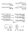
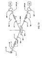
- FIG. 5 An example of another retarder system, which is not an embodiment of the invention claimed herein, is shown in Fig. 5 .
- Each triangular shaped prism has first (TS1) and second (TS2) sides of equal length which project from one another at an angle greater than ninety degrees therebetween, and a third side (TS3) oriented opposite said greater than ninety degree angle.
- the at least two similar triangular shaped prisms are oriented with respect to one another such that the third (TS3) sides thereof are substantially collinear.
- a beam of electromagnetic radiation caused to enter the first side of the first thereof, at a non-normal angle thereto, is refracted so that it internally reflects from said third side thereof, then exits said second side thereof in a direction such that it then enters the first side of another thereof at a non-normal angle thereto, is refracted so that it internally reflects from said third side thereof, then exits said second side thereof.
- the prisms can be fabricated from fused silica.
- FIG. 6 Another embodiment of a new retarder system, which is not embodiment of the claimed invention, is shown in Fig. 6 .
- the parallelogram shaped rhombs each have first (RS1), second (RS2), third (RS3) and fourth (RS4) sides, the first (RS1) and third (RS3) sides being parallel to one another, and the second (RS2) and fourth (RS4) sides being parallel to one another.
- the first (RS1) and second (RS2), and third (RS3) and fourth (RS4) sides of the first parallelogram shaped rhomb meet one another at angles greater than ninety degrees therebetween, and the second (RS2) and third (RS3) sides and the first (RS1) and fourth (RS4) sides thereof meet one another at angles less than ninety degrees therebetween.
- the two parallelogram shaped rhombs are oriented with their second (RS2) sides being substantially colinear and with their fourth (RS4) sides thereof being substantially colinear, such that a beam of electromagnetic radiation caused to enter the first side (RS1) of the first parallelogram shaped rhomb, at a non-normal angle thereto, is refracted so that it internally reflects from said fourth (RS4) and second (RS2) sides thereof, then exits said third (RS3) side thereof in a direction such that it then enters the first (RS1) side of the second thereof at a non-normal angle thereto, is refracted so that it internally reflects from said second (RS2) and fourth (RS4) side thereof, then exits said third (RS3) side thereof.
- the parallelogram shaped rhomb can be fabricated from fused silica.
- Both of the arrangments shown in Figs. 5 and 6 have input and output surfaces into which a beam is entered, and out of which it exits. These surfaces serve to refract the beam in use. Other surfaces at which total internal reflection occurs are used to enter retardance. It is noted that the Fresnel losses at the refracting interfaces result in a relative attenuation for orthogonally polarized beams.
- the orthogonal beams are typically denoted p and s for light polarized parallel and perpendicular to the plane of incidence.
- the relative attenuation and retardation of an optical element can be quantified by the equation below, which is similar to the standard ellipsometry definition.
- the ( ⁇ ) value depends on the number and angle of refracting surfaces in the design. For the triangle design ( ⁇ ) is about 57 degrees, and for the rhomb design ( ⁇ ) is about 53 degrees.
- ( ⁇ ) Since ( ⁇ ) is dependent on the index of refraction, it varies a few degrees over the 190 - 1700 nm spectral range). While the ( ⁇ ) value of the retarder does have to be determined in the ellipsometer/polarimeter system calibration, the sensitivity and accuracy of the instrument has been found to not be significantly degraded as long as ( ⁇ ) is not too far from 45 degrees. It is noted that the beam enters and exits the elements at near a Brewster angle of incidence, hence substantially 100% of the p polarized light is transmitted through the system.
- Figs. 7a, 7b, 8a and 8b show that if the sequential elements are translated up or down as a unit, the exiting beam remains collinear with the input beam. If the sequential elements are rotated, Figs. 9a, 9b, 10a and 10b show that the exiting beam angle is unchanged, (though it is slightly translated).
- Figs. 11 a, 11 b, 11 c, 11 d, 11e, 11f show that the most useful property of the new retarder design is that as the angle of the input beam is changed, the resulting polarization properties ( ⁇ ) and ( ⁇ ) change very little. This is because the geometry and symmetry of the designs are such that changes in the refraction and total internal reflection angles have opposite signs for the two elements shown in the system of Figs. 7a, 7b, 8a and 8b , which in turn cancels change in ( ⁇ ) and ( ⁇ ) vs. input beam angle to a 1 st order approximation. Typically the change in ( ⁇ ) and ( ⁇ ) for a one degree change in beam angle is approximately 0.01 degree. Note that Figs. 11a - 11f show that:
- the net relative attenuation and retardance ( ⁇ ) and (A) of the system can be controlled by adjusting the number of total internal reflections (determined by the number and length of the elements), the angles of refraction and reflection (determined by the prism and/or rhomb angles), and the material used to fabricate the elements.
- any transparent, optically isotropic material can be used for the elements, though care should be taken in mounting the elements to minimize strain-induced birefringence.
- Fused silica is ideal for the UV-VIS-NIR spectral range, but CaF2 is preferable in the DUV, and Si, Ge, ZnSe, KRS5, etc. are suited for use in the IR.
- preferred embodiment designs use fused silica, and have the following properties over a wide 190 - 1700 nm spectral range:
- FIG. 12a demonstrates a system for accomplishing this by allowing translation and/or rotation of an element
- Fig. 12b shows an additional sequential two wedge (w1) (w2) system wherein relative rotation of one wedge with respect to the other provides a similar benefit.
- a system can then include at least one selection from the group consisting of:
- This system for each of a Reflection and Transmission mode comprises:
- the ellipsometer or polarimeter system also has at least one rotatable compensator (C) (C') (C") present at at least one location selected from the group consisting of:
- the at least one rotatable compensator (C) (C') (C") comprises at least two sequential elements oriented with respect to one another such that said entered electromagnetic beam undergoes total internal reflection at least once in each of the elements, with the orientation, geometry, and symmetry of the elements being such that the output beam position is undevlated by a translation of the system, and the output beam angle is undeviated by a rotation of the system.
- Two triangular shaped prisms may be used for the elements, and the angles of the triangular prisms are 26, 128, and 26 degrees.
- the fabrication of the prisms can be from fused silica.
- two parallelogram shaped rhombs may be used for the elements, with the angles of the parallelogram shaped rhombs being 36, 144, 36, and 144 degrees.
- the fabrication of the parallelogram can be from fused silica.
- Fig. 14 shows an example of an ellipsometer or polarimeter system, comprising a source (LS) of polychromatic beam of electromagnetic radiation, a first aperture (A1), a second aperture (A2), a fixed polarizer (P), a rotating compensator (C), a third aperture (A3), a fourth aperture (A4), a first substantially achromatic lens (AL1), a fifth aperture (A5), a stage (STG) for supporting a material system, a sixth aperture (A6), a second substantially achromatic lens (AL2), a seventh aperture (A7), an eighth aperture (A8), a fixed analyzer (A), a ninth aperture (A9), a third substantially achromatic lens (AL3), an optical fiber (OF) and a detector system (DET) which contains a dispersive element and a multiplicity of detector elements.
- LS source
- A1 first aperture
- A2 a second aperture
- P fixed polarizer
- C rotating compensator
- UV filter (F1) present between said source (LS) of polychromatic beam of electromagnetic radiation and said stage (STG) for supporting a material system.
- said fixed analyzer (A) and fixed polarizer (P) are maintained essentially fixed in position and said rotating compensator (C) is caused to continuously rotate while a polychromatic beam of electromagnetic radiation produced by said source (LS) of a polychromatic beam of electromagnetic radiation is sequentially caused to pass through said first aperture (A1), second aperture (A2), fixed polarizer (P), rotating compensator (C), third aperture (A3), fourth aperture (A4), first substantially achromatic lens (AL1), and the fifth aperture (A5).
- the polychromatic beam of electromagnetic radiation also passes through said UV filter, then interacts with a material systems (MS) placed on said stage (STG) for supporting a material system (MS). Then, sequentially, the beam passes through said sixth (A6) aperture, second substantially achromatic lens (AL2), seventh aperture (A7), eighth aperture (A8), fixed analyzer (A), ninth aperture (A9), third substantially achromatic lens (AL3), optionally passes through a beam shaping aperture (A10), and then enters said optical fiber (OF) and passes therethrough to enter said detector system (DET).
- MS material systems
- Fig. 15 illustrates another ellipsometer or polarimeter system, similar to that of Fig. 13 .
- a Material System (MS) under investigation by a Spectroscopic Rotating compensator Material system investigation system is positioned upon the Material System Supporting Stage (STG).
- STG Material System Supporting Stage
- a Material System (Sample), (MS) can be positioned in a Magneto-Optic System which is physically too large to be supported by said Material System Supporting Stage (STG), or in an environmental control chamber.
- the system of Fig. 13 , 14 or 15 can be placed into an evacuated or purged, (eg. by nitrogen or argon), Chamber to the end that UV absorbing Oxygen and Water Vapor are not present therewithin.
- Fig. 13 , 14 or 15 The entire Fig. 13 , 14 or 15 system can be so encompassed within a said Chamber, or only the Sample (MS) Stage portion thereof.
- the Chamber can be of multiple region construction.
- Fig. 16 shows a Chamber (CHA) which can be interpreted to contain one or multiple interior regions and
- Fig. 17 shows a one region environmental control chamber (CHA).
- the rhombs (eg. (R1) and (R2) in Fig. 4d ), are oriented as functional mirror images of each other, while the side the input beam enters is, in both instances, labeled (RS1). It is felt this was the best way to describe the invention. However, it might lead to some confusion regarding angles between, say, sides (RS1) and (RS2). In the foregoing discussion that angle is identified as being greater than 90 degrees. This is valid for the first (RS1) shown rhomb. For purposes of understanding the foregoing discussion, however, in mirror image the sides (RS1) and (RS3) in the second rhomb (RS2) can be considered reversed when the angles therebetween are described as are those in the first rhomb (RS1).
Landscapes
- Physics & Mathematics (AREA)
- General Physics & Mathematics (AREA)
- Optics & Photonics (AREA)
- General Health & Medical Sciences (AREA)
- Pathology (AREA)
- Chemical & Material Sciences (AREA)
- Analytical Chemistry (AREA)
- Biochemistry (AREA)
- Health & Medical Sciences (AREA)
- Immunology (AREA)
- Life Sciences & Earth Sciences (AREA)
- Spectroscopy & Molecular Physics (AREA)
- Polarising Elements (AREA)
- Investigating Or Analysing Materials By Optical Means (AREA)
- Optical Elements Other Than Lenses (AREA)
- Spectrometry And Color Measurement (AREA)
- Optical Radar Systems And Details Thereof (AREA)
Abstract
Claims (5)
- Système pour introduire un retard de phase relative dans des composantes polarisées orthogonalement d'un faisceau électromagnétique appliqué dans celui-ci, ledit système comprenant au moins deux éléments séquentiels orientés l'un par rapport à l'autre de sorte que ledit faisceau électromagnétique appliqué subisse une réflexion interne totale au moins une fois dans chacun des au moins deux éléments ;
la séquence, l'orientation, la géométrie et la symétrie des éléments étant telle que le lieu géométrique d'un faisceau de sortie soit sensiblement non dévié par rapport au lieu géométrique du faisceau d'entrée ;
dans lequel deux desdits éléments séquentiels sont des rhomboèdres en forme de parallélogramme, chacun desdits rhomboèdres ayant des premier (RS1), deuxième (RS2), troisième (RS3) et quatrième (RS4) côtés, lesdits premier (RS1) et troisième (RS3) côtés étant parallèles l'un à l'autre et lesdits deuxième (RS2) et quatrième (RS4) côtés étant parallèles l'un à l'autre, lesdits premier (RS1) et deuxième (RS2) côtés dudit premier rhomboèdre en forme de parallélogramme et lesdits deuxième (RS2) et troisième (RS3) côtés dudit deuxième rhomboèdre en forme de parallélogramme se rencontrant l'un l'autre selon des angles supérieurs à quatre-vingt-dix degrés entre eux, et lesdits deuxième (RS2) et troisième (RS3) côtés dudit premier rhomboèdre en forme de parallélogramme et lesdits premier (RS1) et deuxième (RS2) côtés dudit deuxième rhomboèdre en forme de parallélogramme se rencontrant l'un l'autre selon des angles inférieurs à quatre-vingt-dix degrés entre eux,
lesdits au moins deux rhomboèdres en forme de parallélogramme étant orientés avec leurs premier et troisième côtés étant sensiblement parallèles entre eux ;
par lequel un faisceau d'entrée de rayonnement électromagnétique, forcé à passer à travers le premier côté (RS1) d'un rhomboèdre en forme de parallélogramme, avec un angle sensiblement normal à celui-ci, poursuit ensuite de sorte qu'il est réfléchi à l'intérieur par lesdits quatrième (RS4) et deuxième (RS2) côtés de celui-ci, et sort ensuite dudit troisième côté (RS3) dans une direction telle qu'il passe ensuite à travers le premier côté (RS1) du deuxième rhomboèdre en forme de parallélogramme avec un angle sensiblement normal à celui-ci, et poursuit ensuite de sorte qu'il est réfléchi à l'intérieur par lesdits deuxième (RS2) et quatrième (RS4) côtés de celui-ci, et sort ensuite dudit troisième côté (RS3) de celui-ci ;
ledit système étant caractérisé en ce qu'il est destiné à être utilisé sur une plage spectrale de 190 à 1700 nm, en ce que les rhomboèdres en forme de parallélogramme sont réalisés chacun en silice fondue, en ce qu'au moins un des deuxième (RS2) et quatrième (RS4) côtés d'au moins un des rhomboèdres en forme de parallélogramme a sur celui-ci un revêtement de MgF2 qui a un indice de réfraction inférieur à celui de la silice fondue qui constitue le rhomboèdre en forme de parallélogramme correspondant, et en ce que le revêtement de MgF2 est entre 30-45 nm. - Système selon la revendication 1, dans lequel les angles des rhomboèdres en forme de parallélogramme sont de 36, 144, 36 et 144 degrés, ou de 45, 135, 45 et 135 degrés.
- Système selon la revendication 1, dans lequel le revêtement de MgF2 est de 35 nm.
- Système selon la revendication 1, dans lequel un des rhomboèdres en forme de parallélogramme est formé par une combinaison de deux éléments séquentiels (ra) et (rb) et l'autre rhomboèdre en forme de parallélogramme est formé par une combinaison de deux éléments séquentiels (rc) et (rd), chacun desdits éléments séquentiels étant un prisme rectangle ayant des côtés à angle droit adjacents à son angle droit et un côté (ha, hb, hc, hd) opposé à l'angle droit de celui-ci ; lesdits prismes rectangles étant orientés l'un par rapport à l'autre de sorte que, tels que vus en élévation latérale, le premier prisme rectangle (ra) est positionné de sorte que son côté (ha) opposé à l'angle droit est orienté vers le bas et vers la droite, et de sorte que directement au-dessus du premier prisme rectangle (ra) se trouve le deuxième prisme rectangle (rb), qui est orienté de sorte que son côté (hb) opposé à l'angle droit de celui-ci est orienté vers le haut et vers la gauche, et de sorte qu'immédiatement à droite du deuxième prisme rectangle (rb) se trouve le troisième prisme rectangle (rc) qui est orienté de sorte que son côté (hc) opposé à l'angle droit de celui-ci est orienté vers le haut et vers la droite, et de sorte que directement au-dessous du troisième prisme rectangle (rc) se trouve le quatrième prisme rectangle (rd), orienté de sorte que son côté (hd) opposé à l'angle droit de celui-ci est orienté vers le bas et vers la gauche.
- Système selon la revendication 1 ou la revendication 4, comprenant en outre au moins une sélection effectuée parmi le groupe comprenant :au moins un des éléments séquentiels a un mécanisme pour la translation et/ou le basculement de l'élément, dans le but d'aligner le système de sorte que le faisceau de sortie soit sensiblement non dévié par rapport audit faisceau d'entrée ;au moins un des éléments séquentiels a un revêtement sur une surface de celui-ci à travers lequel le faisceau de rayonnement électromagnétique entre ou sort, ledit revêtement ayant un indice de réfraction différent de celui du matériau qui constitue ledit élément correspondant ;un système additionnel de coins multiples séquentiels est présent dans ledit système pour introduire un retard de phase relative dans des composantes polarisées orthogonalement d'un faisceau électromagnétique, dans lequel un desdits coins (w1) peut être pivoté par rapport à un autre (w2) et/ou les deux coins (w1, w2) peuvent être pivotés simultanément, dans le but d'aligner le système de sorte que le faisceau de sortie est sensiblement non dévié par rapport audit faisceau d'entrée.
Applications Claiming Priority (3)
| Application Number | Priority Date | Filing Date | Title |
|---|---|---|---|
| US11/590,408 US7460230B2 (en) | 2005-11-04 | 2006-10-31 | Deviation angle self compensating substantially achromatic retarder |
| US11/633,138 US7450231B2 (en) | 2005-11-04 | 2006-12-04 | Deviation angle self compensating substantially achromatic retarder |
| PCT/US2007/015695 WO2008054558A2 (fr) | 2006-10-31 | 2007-07-10 | Retardateur sensiblement achromatique à compensation autonome de l'angle de déviation |
Publications (3)
| Publication Number | Publication Date |
|---|---|
| EP2062018A2 EP2062018A2 (fr) | 2009-05-27 |
| EP2062018A4 EP2062018A4 (fr) | 2009-10-21 |
| EP2062018B1 true EP2062018B1 (fr) | 2012-03-07 |
Family
ID=39344822
Family Applications (1)
| Application Number | Title | Priority Date | Filing Date |
|---|---|---|---|
| EP07810297A Active EP2062018B1 (fr) | 2006-10-31 | 2007-07-10 | Retardateur sensiblement achromatique à compensation autonome de l'angle de déviation |
Country Status (5)
| Country | Link |
|---|---|
| US (1) | US7450231B2 (fr) |
| EP (1) | EP2062018B1 (fr) |
| JP (2) | JP2010508511A (fr) |
| KR (1) | KR101335567B1 (fr) |
| WO (1) | WO2008054558A2 (fr) |
Families Citing this family (84)
| Publication number | Priority date | Publication date | Assignee | Title |
|---|---|---|---|---|
| US11026768B2 (en) | 1998-10-08 | 2021-06-08 | Align Technology, Inc. | Dental appliance reinforcement |
| US9492245B2 (en) | 2004-02-27 | 2016-11-15 | Align Technology, Inc. | Method and system for providing dynamic orthodontic assessment and treatment profiles |
| US7907280B2 (en) * | 2005-11-04 | 2011-03-15 | J.A. Woollam Co., Inc. | Method of constructing a deviation angle self compensating substantially achromatic retarder to compensate beam traslation |
| US8462341B2 (en) | 2005-11-04 | 2013-06-11 | J.A. Woollam Co., Inc. | Mounting for deviation angle self compensating substantially achromatic retarder |
| US7878805B2 (en) | 2007-05-25 | 2011-02-01 | Align Technology, Inc. | Tabbed dental appliance |
| US8738394B2 (en) | 2007-11-08 | 2014-05-27 | Eric E. Kuo | Clinical data file |
| US8108189B2 (en) | 2008-03-25 | 2012-01-31 | Align Technologies, Inc. | Reconstruction of non-visible part of tooth |
| US9492243B2 (en) | 2008-05-23 | 2016-11-15 | Align Technology, Inc. | Dental implant positioning |
| US8092215B2 (en) | 2008-05-23 | 2012-01-10 | Align Technology, Inc. | Smile designer |
| US8172569B2 (en) | 2008-06-12 | 2012-05-08 | Align Technology, Inc. | Dental appliance |
| US8152518B2 (en) | 2008-10-08 | 2012-04-10 | Align Technology, Inc. | Dental positioning appliance having metallic portion |
| JP4711009B2 (ja) | 2008-10-16 | 2011-06-29 | ソニー株式会社 | 光学的測定装置 |
| US8416408B1 (en) | 2009-02-27 | 2013-04-09 | J.A. Woollam Co., Inc. | Terahertz-infrared ellipsometer system, and method of use |
| US8169611B2 (en) | 2009-02-27 | 2012-05-01 | University Of Nebraska Board Of Regents | Terahertz-infrared ellipsometer system, and method of use |
| US8934096B2 (en) | 2009-02-27 | 2015-01-13 | University Of Nebraska Board Of Regents | Terahertz-infrared ellipsometer system, and method of use |
| US8736838B2 (en) | 2009-02-27 | 2014-05-27 | J.A. Woollam Co., Inc. | Terahertz ellipsometer system, and method of use |
| US8488119B2 (en) | 2009-02-27 | 2013-07-16 | J.A. Woollam Co., Inc. | Terahertz-infrared ellipsometer system, and method of use |
| US8292617B2 (en) | 2009-03-19 | 2012-10-23 | Align Technology, Inc. | Dental wire attachment |
| US8765031B2 (en) | 2009-08-13 | 2014-07-01 | Align Technology, Inc. | Method of forming a dental appliance |
| US9241774B2 (en) | 2010-04-30 | 2016-01-26 | Align Technology, Inc. | Patterned dental positioning appliance |
| US9211166B2 (en) | 2010-04-30 | 2015-12-15 | Align Technology, Inc. | Individualized orthodontic treatment index |
| US9403238B2 (en) | 2011-09-21 | 2016-08-02 | Align Technology, Inc. | Laser cutting |
| WO2013101252A1 (fr) * | 2011-12-31 | 2013-07-04 | J.A. Woollam Co., Inc. | Ellipsomètre térahertz et procédé d'utilisation |
| US9375300B2 (en) | 2012-02-02 | 2016-06-28 | Align Technology, Inc. | Identifying forces on a tooth |
| JP6097703B2 (ja) | 2012-02-08 | 2017-03-15 | 学校法人 埼玉医科大学 | 軸対称偏光変換素子 |
| US9220580B2 (en) | 2012-03-01 | 2015-12-29 | Align Technology, Inc. | Determining a dental treatment difficulty |
| US9414897B2 (en) | 2012-05-22 | 2016-08-16 | Align Technology, Inc. | Adjustment of tooth position in a virtual dental model |
| US10772506B2 (en) | 2014-07-07 | 2020-09-15 | Align Technology, Inc. | Apparatus for dental confocal imaging |
| US9693839B2 (en) * | 2014-07-17 | 2017-07-04 | Align Technology, Inc. | Probe head and apparatus for intraoral confocal imaging using polarization-retarding coatings |
| US9675430B2 (en) | 2014-08-15 | 2017-06-13 | Align Technology, Inc. | Confocal imaging apparatus with curved focal surface |
| US10449016B2 (en) | 2014-09-19 | 2019-10-22 | Align Technology, Inc. | Arch adjustment appliance |
| US9610141B2 (en) | 2014-09-19 | 2017-04-04 | Align Technology, Inc. | Arch expanding appliance |
| CN104317064A (zh) * | 2014-09-24 | 2015-01-28 | 福建福晶科技股份有限公司 | 一种宽带消色差补偿器 |
| EP3204754B1 (fr) | 2014-10-06 | 2022-09-14 | Applied Photophysics Limited | Dispositif d'étalonnage et ses utilisations |
| US9744001B2 (en) | 2014-11-13 | 2017-08-29 | Align Technology, Inc. | Dental appliance with cavity for an unerupted or erupting tooth |
| US10504386B2 (en) | 2015-01-27 | 2019-12-10 | Align Technology, Inc. | Training method and system for oral-cavity-imaging-and-modeling equipment |
| CN105181604A (zh) * | 2015-05-11 | 2015-12-23 | 福州大学 | 一种多角度入射单发椭偏测量方法 |
| US10248883B2 (en) | 2015-08-20 | 2019-04-02 | Align Technology, Inc. | Photograph-based assessment of dental treatments and procedures |
| US11554000B2 (en) | 2015-11-12 | 2023-01-17 | Align Technology, Inc. | Dental attachment formation structure |
| US11931222B2 (en) | 2015-11-12 | 2024-03-19 | Align Technology, Inc. | Dental attachment formation structures |
| US11596502B2 (en) | 2015-12-09 | 2023-03-07 | Align Technology, Inc. | Dental attachment placement structure |
| US11103330B2 (en) | 2015-12-09 | 2021-08-31 | Align Technology, Inc. | Dental attachment placement structure |
| EP3471599B1 (fr) | 2016-06-17 | 2025-11-19 | Align Technology, Inc. | Appareils intraoraux avec détection |
| WO2017218951A1 (fr) | 2016-06-17 | 2017-12-21 | Align Technology, Inc. | Dispositif de surveillance de performances d'un appareil orthodontique |
| WO2018022940A1 (fr) | 2016-07-27 | 2018-02-01 | Align Technology, Inc. | Scanner intra-buccal pouvant établir un diagnostic dentaire |
| US10507087B2 (en) | 2016-07-27 | 2019-12-17 | Align Technology, Inc. | Methods and apparatuses for forming a three-dimensional volumetric model of a subject's teeth |
| US10595966B2 (en) | 2016-11-04 | 2020-03-24 | Align Technology, Inc. | Methods and apparatuses for dental images |
| US11026831B2 (en) | 2016-12-02 | 2021-06-08 | Align Technology, Inc. | Dental appliance features for speech enhancement |
| EP3547950A1 (fr) | 2016-12-02 | 2019-10-09 | Align Technology, Inc. | Procédés et appareils pour personnaliser des dispositifs d'expansion palatine rapides à l'aide de modèles numériques |
| US11376101B2 (en) | 2016-12-02 | 2022-07-05 | Align Technology, Inc. | Force control, stop mechanism, regulating structure of removable arch adjustment appliance |
| CN114224534B (zh) | 2016-12-02 | 2025-02-18 | 阿莱恩技术有限公司 | 腭扩张器和扩张腭的方法 |
| US10548700B2 (en) | 2016-12-16 | 2020-02-04 | Align Technology, Inc. | Dental appliance etch template |
| US10456043B2 (en) | 2017-01-12 | 2019-10-29 | Align Technology, Inc. | Compact confocal dental scanning apparatus |
| US10779718B2 (en) | 2017-02-13 | 2020-09-22 | Align Technology, Inc. | Cheek retractor and mobile device holder |
| WO2018183358A1 (fr) | 2017-03-27 | 2018-10-04 | Align Technology, Inc. | Appareils et procédés d'aide à des thérapies dentaires |
| US10613515B2 (en) | 2017-03-31 | 2020-04-07 | Align Technology, Inc. | Orthodontic appliances including at least partially un-erupted teeth and method of forming them |
| US11045283B2 (en) | 2017-06-09 | 2021-06-29 | Align Technology, Inc. | Palatal expander with skeletal anchorage devices |
| CN116942335A (zh) | 2017-06-16 | 2023-10-27 | 阿莱恩技术有限公司 | 牙齿类型和萌出状态的自动检测 |
| US10639134B2 (en) | 2017-06-26 | 2020-05-05 | Align Technology, Inc. | Biosensor performance indicator for intraoral appliances |
| US10885521B2 (en) | 2017-07-17 | 2021-01-05 | Align Technology, Inc. | Method and apparatuses for interactive ordering of dental aligners |
| WO2019018784A1 (fr) | 2017-07-21 | 2019-01-24 | Align Technology, Inc. | Ancrage de contour palatin |
| CN110996836B (zh) | 2017-07-27 | 2023-04-11 | 阿莱恩技术有限公司 | 用于通过光学相干断层扫描术来处理正畸矫正器的系统和方法 |
| WO2019023461A1 (fr) | 2017-07-27 | 2019-01-31 | Align Technology, Inc. | Teinte, transparence et émaillage dentaire |
| US12274597B2 (en) * | 2017-08-11 | 2025-04-15 | Align Technology, Inc. | Dental attachment template tray systems |
| WO2019035979A1 (fr) | 2017-08-15 | 2019-02-21 | Align Technology, Inc. | Évaluation et calcul de couloir buccal |
| WO2019036677A1 (fr) | 2017-08-17 | 2019-02-21 | Align Technology, Inc. | Surveillance de conformité d'appareil dentaire |
| US12171575B2 (en) | 2017-10-04 | 2024-12-24 | Align Technology, Inc. | Intraoral systems and methods for sampling soft-tissue |
| US10813720B2 (en) | 2017-10-05 | 2020-10-27 | Align Technology, Inc. | Interproximal reduction templates |
| WO2019084326A1 (fr) | 2017-10-27 | 2019-05-02 | Align Technology, Inc. | Autres structures de réglage de morsure |
| CN116602778A (zh) | 2017-10-31 | 2023-08-18 | 阿莱恩技术有限公司 | 具有选择性牙合负荷和受控牙尖交错的牙科器具 |
| EP3703607B1 (fr) | 2017-11-01 | 2025-03-26 | Align Technology, Inc. | Planification automatique de traitement |
| US11534974B2 (en) | 2017-11-17 | 2022-12-27 | Align Technology, Inc. | Customized fabrication of orthodontic retainers based on patient anatomy |
| CN118948478A (zh) | 2017-11-30 | 2024-11-15 | 阿莱恩技术有限公司 | 用于监测口腔矫治器的传感器 |
| WO2019118876A1 (fr) | 2017-12-15 | 2019-06-20 | Align Technology, Inc. | Méthodes et appareils de traitement orthodontique adaptatif à boucle fermée |
| US10980613B2 (en) | 2017-12-29 | 2021-04-20 | Align Technology, Inc. | Augmented reality enhancements for dental practitioners |
| JP7427595B2 (ja) | 2018-01-26 | 2024-02-05 | アライン テクノロジー, インコーポレイテッド | 診断の為の口腔内のスキャン及び追跡 |
| US11937991B2 (en) | 2018-03-27 | 2024-03-26 | Align Technology, Inc. | Dental attachment placement structure |
| WO2019200008A1 (fr) | 2018-04-11 | 2019-10-17 | Align Technology, Inc. | Appareils d'expansion palatine libérables |
| JP6876189B1 (ja) * | 2020-08-11 | 2021-05-26 | 株式会社光学技研 | フレネルロム、該フレネルロムを備えた計測装置及び光アッテネーター |
| US11733534B2 (en) * | 2021-01-21 | 2023-08-22 | AdlOptica Optical Systems GmbH | Optics for formation of multiple light spots with controlled spot intensity and variable spot pattern geometry |
| JP7621141B2 (ja) * | 2021-03-05 | 2025-01-24 | 株式会社光学技研 | 広帯域円偏光子及び該広帯域円偏光子を備えた計測装置 |
| JP7221320B2 (ja) * | 2021-03-05 | 2023-02-13 | 株式会社光学技研 | 広帯域位相子、該広帯域位相子を備えた計測装置及び光アッテネーター |
| US11906770B2 (en) * | 2021-10-21 | 2024-02-20 | KLA Corporal | Monolithic optical retarder |
| JP7221433B1 (ja) | 2022-02-03 | 2023-02-13 | 株式会社光学技研 | 光学素子及び光学素子の製造方法 |
Family Cites Families (24)
| Publication number | Priority date | Publication date | Assignee | Title |
|---|---|---|---|---|
| GB1119240A (en) * | 1965-09-23 | 1968-07-10 | Nat Res Dev | Quarterwave retardation systems |
| US4331378A (en) | 1976-10-22 | 1982-05-25 | E. I. Du Pont De Nemours And Company | Reinforced optical fiber cable with glass or silica core |
| DD245489A1 (de) * | 1985-12-31 | 1987-05-06 | Zeiss Jena Veb Carl | Zirkularpolarisationseinrichtung |
| US4822150A (en) * | 1987-05-18 | 1989-04-18 | Eastman Kodak Company | Optical device for rotating the polarization of a light beam |
| GB8720923D0 (en) * | 1987-09-05 | 1987-10-14 | Emi Plc Thorn | Optical image rotators |
| US4917461A (en) * | 1989-01-11 | 1990-04-17 | Goldstein Dennis H | Achromatic infrared retarder |
| JPH0336504A (ja) * | 1989-07-03 | 1991-02-18 | Copal Co Ltd | 光路偏向装置 |
| US6141102A (en) * | 1999-01-19 | 2000-10-31 | J. A. Woolam Co. Inc | Single trianglular shaped optical retarder element for use in spectroscopic ellipsometer and polarimeter systems |
| US5706212A (en) * | 1996-03-20 | 1998-01-06 | Board Of Regents Of University Of Nebraska | Infrared ellipsometer/polarimeter system, method of calibration, and use thereof |
| US6084675A (en) * | 1995-09-20 | 2000-07-04 | J. A. Woollam Co. Inc. | Adjustable beam alignment compensator/retarder with application in spectroscopic ellipsometer and polarimeter systems |
| US6084674A (en) * | 1999-01-04 | 2000-07-04 | J. A. Woollam Co., Inc. | Parallelogram shaped optical retarder element for use in spectroscopic ellipsometer and polarimeter systems |
| US6353477B1 (en) | 1992-09-18 | 2002-03-05 | J. A. Woollam Co. Inc. | Regression calibrated spectroscopic rotating compensator ellipsometer system with pseudo-achromatic retarder system |
| US6118537A (en) * | 1999-01-04 | 2000-09-12 | J. A. Woollam Co. Inc. | Multiple tipped berek plate optical retarder elements for use in spectroscopic ellipsometer and polarimeter systems |
| US6100981A (en) * | 1999-01-04 | 2000-08-08 | J.A. Woollam Co. Inc. | Dual horizontally oriented triangle shaped optical retarder element for use in spectroscopic ellipsometer and polarimeter systems |
| JP3340824B2 (ja) * | 1993-12-13 | 2002-11-05 | レーザーテック株式会社 | 全反射プリズムを含む光学系 |
| US5946098A (en) * | 1997-12-23 | 1999-08-31 | J.A. Woollam Co. Inc. | Optical elements for use in spectroscopic ellipsometer and polarimeter systems |
| US5751482A (en) * | 1996-04-22 | 1998-05-12 | Imation Corp. | Achromatic polarization-rotating right-angle prism system |
| US5706087A (en) | 1996-10-04 | 1998-01-06 | The Board Of Regents Of The University Of Nebraska | Electromagnetic beam directing means-sample analysis system stage, and method of use |
| GB0110492D0 (en) * | 2001-04-28 | 2001-06-20 | Secr Defence | Optical device |
| US6546159B1 (en) * | 2001-08-22 | 2003-04-08 | Avanex Corporation | Method and apparatus for compensating differential group delay |
| US7202418B2 (en) | 2004-01-07 | 2007-04-10 | Cable Components Group, Llc | Flame retardant and smoke suppressant composite high performance support-separators and conduit tubes |
| US20060023308A1 (en) * | 2004-07-29 | 2006-02-02 | Hunt Jeffrey H | Infrared polarization rotation element |
| US7218821B2 (en) | 2004-08-20 | 2007-05-15 | Furukawa Electric North America Inc. | Optical fiber cables |
| US7298480B2 (en) | 2005-12-23 | 2007-11-20 | Ecole Polytechnique | Broadband ellipsometer / polarimeter system |
-
2006
- 2006-12-04 US US11/633,138 patent/US7450231B2/en active Active
-
2007
- 2007-07-10 JP JP2009534564A patent/JP2010508511A/ja not_active Ceased
- 2007-07-10 EP EP07810297A patent/EP2062018B1/fr active Active
- 2007-07-10 KR KR1020087030571A patent/KR101335567B1/ko active Active
- 2007-07-10 WO PCT/US2007/015695 patent/WO2008054558A2/fr not_active Ceased
-
2012
- 2012-02-17 JP JP2012032511A patent/JP5438789B2/ja active Active
Also Published As
| Publication number | Publication date |
|---|---|
| JP5438789B2 (ja) | 2014-03-12 |
| KR101335567B1 (ko) | 2013-12-02 |
| JP2010508511A (ja) | 2010-03-18 |
| WO2008054558A3 (fr) | 2008-09-04 |
| KR20090087812A (ko) | 2009-08-18 |
| US7450231B2 (en) | 2008-11-11 |
| EP2062018A4 (fr) | 2009-10-21 |
| US20080100842A1 (en) | 2008-05-01 |
| WO2008054558A2 (fr) | 2008-05-08 |
| JP2012141623A (ja) | 2012-07-26 |
| EP2062018A2 (fr) | 2009-05-27 |
Similar Documents
| Publication | Publication Date | Title |
|---|---|---|
| EP2062018B1 (fr) | Retardateur sensiblement achromatique à compensation autonome de l'angle de déviation | |
| US7907280B2 (en) | Method of constructing a deviation angle self compensating substantially achromatic retarder to compensate beam traslation | |
| US7460230B2 (en) | Deviation angle self compensating substantially achromatic retarder | |
| US7616319B1 (en) | Spectroscopic ellipsometer and polarimeter systems | |
| US5946098A (en) | Optical elements for use in spectroscopic ellipsometer and polarimeter systems | |
| US6118537A (en) | Multiple tipped berek plate optical retarder elements for use in spectroscopic ellipsometer and polarimeter systems | |
| US6141102A (en) | Single trianglular shaped optical retarder element for use in spectroscopic ellipsometer and polarimeter systems | |
| US6100981A (en) | Dual horizontally oriented triangle shaped optical retarder element for use in spectroscopic ellipsometer and polarimeter systems | |
| US6870621B2 (en) | Small spot ellipsometer | |
| US8462341B2 (en) | Mounting for deviation angle self compensating substantially achromatic retarder | |
| CA2290860C (fr) | Systeme d'eclairage polarisant en contre-jour pour ecrans a cristaux liquides a vision directe | |
| US7245376B2 (en) | Combined spatial filter and relay systems in rotating compensator ellipsometer/polarimeter | |
| Ilyin | Second‐order error propagation in the Mueller matrix of a spectropolarimeter | |
| US7336361B1 (en) | Spectroscopic ellipsometer and polarimeter systems | |
| CN101825785A (zh) | 反射型液晶盒的倾角测定方法以及测定装置 | |
| US7099006B1 (en) | Ellipsometer or polarimeter and the like system with beam chromatic shifting and directing means | |
| US7304737B1 (en) | Rotating or rotatable compensator system providing aberation corrected electromagnetic raadiation to a spot on a sample at multiple angles of a incidence | |
| Packham et al. | CanariCam-Polarimetry: A Dual-Beam 10 m Polarimeter for the GTC | |
| US7193710B1 (en) | Rotating or rotatable compensator spectroscopic ellipsometer system including multiple element lenses | |
| US7215424B1 (en) | Broadband ellipsometer or polarimeter system including at least one multiple element lens | |
| Mahler et al. | Low polarization optical system design | |
| Hodgkinson | Linear and circular form birefringence of coatings fabricated by serial bideposition | |
| US7535566B1 (en) | Beam chromatic shifting and directing means | |
| Ilyin et al. | On the design of the PEPSI spectropolarimeter for the LBT | |
| Sassella et al. | Generalized anisotropic ellipsometry applied to an organic single crystal: Potassium acid phthalate |
Legal Events
| Date | Code | Title | Description |
|---|---|---|---|
| PUAI | Public reference made under article 153(3) epc to a published international application that has entered the european phase |
Free format text: ORIGINAL CODE: 0009012 |
|
| 17P | Request for examination filed |
Effective date: 20081201 |
|
| AK | Designated contracting states |
Kind code of ref document: A2 Designated state(s): AT BE BG CH CY CZ DE DK EE ES FI FR GB GR HU IE IS IT LI LT LU LV MC MT NL PL PT RO SE SI SK TR |
|
| AX | Request for extension of the european patent |
Extension state: AL BA HR MK RS |
|
| A4 | Supplementary search report drawn up and despatched |
Effective date: 20090917 |
|
| 17Q | First examination report despatched |
Effective date: 20100108 |
|
| DAX | Request for extension of the european patent (deleted) | ||
| RBV | Designated contracting states (corrected) |
Designated state(s): DE FR GB |
|
| REG | Reference to a national code |
Ref country code: DE Ref legal event code: R079 Ref document number: 602007021199 Country of ref document: DE Free format text: PREVIOUS MAIN CLASS: G01J0004000000 Ipc: G02B0026060000 |
|
| GRAP | Despatch of communication of intention to grant a patent |
Free format text: ORIGINAL CODE: EPIDOSNIGR1 |
|
| RIC1 | Information provided on ipc code assigned before grant |
Ipc: G02B 5/30 20060101ALI20110913BHEP Ipc: G02B 26/06 20060101AFI20110913BHEP |
|
| GRAS | Grant fee paid |
Free format text: ORIGINAL CODE: EPIDOSNIGR3 |
|
| GRAA | (expected) grant |
Free format text: ORIGINAL CODE: 0009210 |
|
| AK | Designated contracting states |
Kind code of ref document: B1 Designated state(s): DE FR GB |
|
| REG | Reference to a national code |
Ref country code: GB Ref legal event code: FG4D |
|
| REG | Reference to a national code |
Ref country code: DE Ref legal event code: R096 Ref document number: 602007021199 Country of ref document: DE Effective date: 20120503 |
|
| PLBE | No opposition filed within time limit |
Free format text: ORIGINAL CODE: 0009261 |
|
| STAA | Information on the status of an ep patent application or granted ep patent |
Free format text: STATUS: NO OPPOSITION FILED WITHIN TIME LIMIT |
|
| 26N | No opposition filed |
Effective date: 20121210 |
|
| REG | Reference to a national code |
Ref country code: DE Ref legal event code: R097 Ref document number: 602007021199 Country of ref document: DE Effective date: 20121210 |
|
| REG | Reference to a national code |
Ref country code: FR Ref legal event code: PLFP Year of fee payment: 10 |
|
| REG | Reference to a national code |
Ref country code: FR Ref legal event code: PLFP Year of fee payment: 11 |
|
| REG | Reference to a national code |
Ref country code: FR Ref legal event code: PLFP Year of fee payment: 12 |
|
| PGFP | Annual fee paid to national office [announced via postgrant information from national office to epo] |
Ref country code: GB Payment date: 20250529 Year of fee payment: 19 |
|
| PGFP | Annual fee paid to national office [announced via postgrant information from national office to epo] |
Ref country code: FR Payment date: 20250610 Year of fee payment: 19 |
|
| PGFP | Annual fee paid to national office [announced via postgrant information from national office to epo] |
Ref country code: DE Payment date: 20250604 Year of fee payment: 19 |