EP2062060B1 - Tête de mesure et procédé de mesure - Google Patents
Tête de mesure et procédé de mesure Download PDFInfo
- Publication number
- EP2062060B1 EP2062060B1 EP07730591.0A EP07730591A EP2062060B1 EP 2062060 B1 EP2062060 B1 EP 2062060B1 EP 07730591 A EP07730591 A EP 07730591A EP 2062060 B1 EP2062060 B1 EP 2062060B1
- Authority
- EP
- European Patent Office
- Prior art keywords
- hole
- measuring
- electrode
- measuring head
- insulating
- Prior art date
- Legal status (The legal status is an assumption and is not a legal conclusion. Google has not performed a legal analysis and makes no representation as to the accuracy of the status listed.)
- Active
Links
Images
Classifications
-
- G—PHYSICS
- G01—MEASURING; TESTING
- G01V—GEOPHYSICS; GRAVITATIONAL MEASUREMENTS; DETECTING MASSES OR OBJECTS; TAGS
- G01V3/00—Electric or magnetic prospecting or detecting; Measuring magnetic field characteristics of the earth, e.g. declination, deviation
- G01V3/18—Electric or magnetic prospecting or detecting; Measuring magnetic field characteristics of the earth, e.g. declination, deviation specially adapted for well-logging
- G01V3/20—Electric or magnetic prospecting or detecting; Measuring magnetic field characteristics of the earth, e.g. declination, deviation specially adapted for well-logging operating with propagation of electric current
Definitions
- the invention relates to various electrical measurements conducted in holes drilled in the ground, and in particular in a rocky soil, for investigating the soil quality.
- the invention focuses specifically on the measuring head used in the measurements, and on the actual measuring method.
- the so called single point resistance is based on measuring the resistance between an electrode placed in a hole drilled in the ground and the surroundings of the hole.
- SPR single point resistance
- the resistance by a solid rock is high, but typically decreases significantly by rock fractures or clefts filled with water. The resistance can thus be used when investigating the positions of clefts or the like.
- Another known method is mise a la masse. It involves feeding electric current into an electrode, which is placed in a hole drilled in the ground, and measuring the voltage from other holes drilled in the ground at a distance from the first hole.
- an electrode which is placed in a hole drilled in the ground
- measuring the voltage from other holes drilled in the ground at a distance from the first hole When the current electrode is placed in a conductive area, for example by a wet rock cleft or ore deposit, a nearly constant potential is formed in said area. The higher the resistance of the area outside the conductive area, the faster is the decrease in the potential outside the conductive area. Examining the voltage in and outside the conductive area allows thus the determination of geometry, and also, to some extent, of conductivity of the conductive area.
- the electrical measuring area should be limited near the electrode.
- the resistance for instance by a rock cleft does not necessarily differ much from the resistance between the electrode and the walls of the hole in other parts of the hole.
- the current fed through an electrode may migrate both upwards and downwards in the conductive hole, and further to other clefts than the ones the investigation is focused on.
- a conductive area i.e. a cleft
- it is not certain that the cleft in question is the one into which the current is fed. The resolution of these methods is therefore inadequate.
- Further methods include a focused through-casing method in a petroleum well in US 2001/0033164 , a soil-surveying method in JP H05 346017 , a method for investigating earth formations in US 3882376 , a method for electrical borehole logging in US 2874347 and a method utilizing a flow meter in US 5804714 .
- the objective of the invention is to alleviate the problem referred to above and thereby improve the accuracy of electrical measurements conducted in holes drilled in the ground.
- the measuring head and the measuring method of the invention are characterized by what has been presented in claims 1 and 5, respectively.
- the measuring head of the invention for use in electrical measurements conducted in holes drilled in the ground comprises an elongated body, adjustable to the hole, which body comprises an electrode, electrically connecting the measuring head with its surroundings, for transmitting an electrical signal between the measuring head and its surroundings.
- the body has a significantly smaller profile than the hole used for measuring, so that it can be easily placed in the hole.
- the outer surface of the body is typically made, except for the electrode area, from plastic or other insulating material, such that the metal-coated electrode is the only part of the measuring head having electrical contact with the surroundings of the measuring head.
- the signal transmission in this context may be directed from the electrode to the surroundings, such as when supplying the current signal in mise a la masse, but the same measuring head construction is as well equally suitable for receiving the voltage signal of the mise a la masse method.
- the measuring head comprises insulating means, placed on the body on both sides of the electrode along the length of the hole to form a measuring area, electrically insulated from other parts of the hole, around the electrode placed in the hole.
- Delimiting the measuring area in this way provides significant improvement to the measuring resolution, because the area into which the signal is fed or, respectively, in which the signal is received is limited near the electrode. For example in mise a la masse, this ensures that current is fed only into the desired rock cleft or other conductive area, and, respectively, by voltage measurements of limited coverage area, the conductive area determined in this way is known to be in contact with the exact and same area.
- the insulating means are preferably flexible and elastic, plate-like insulating sheets, arranged around the body and having a free diameter which is at least equal to that of the hole. They can be made for example from plastic or rubber.
- the free diameter of the flexible insulating sheet herein means the diameter in the transverse direction of the body when the measuring head is not placed in the hole.
- a flexible insulating sheet having a diameter larger than that of the hole is, when the measuring head is placed in the hole, pressed tightly against the walls of the hole, at the same time efficiently breaking the electrical connection lengthwise in the hole. Even if the sheets are not pressed completely tightly against the wall, the electrical conductivity past the insulating sheet will in any case decrease significantly.
- Such insulating sheets are very simple, and therefore cost-effective, means for realizing electrical insulation.
- the insulating sheets curve in one direction along the length of the body, such that they follow the movements of the measuring head in the hole in one direction, and, when the measuring head moves in the opposite direction, become tighter pressed against the walls of the hole.
- the curving may be directed, for example, toward the upper end of the measuring head, which facilitates the placement of the measuring head into the hole, and the measuring area can be tightly insulated by lifting the measuring head slightly upwards at the desired depth.
- one preferred embodiment of the invention comprises, on both sides of the electrode, at least two successive insulating sheets along the length of the body. In this way, a possibly insufficient insulation capacity of one insulating sheet does not compromise efficient electrical insulation.
- the insulating means are preferably arranged to move along the length of the body for adjusting the length of the measuring area, arranged around the electrode and electrically insulated from other parts of the hole.
- the method involves electrically insulating, along the length of the hole, the surroundings of the electrode from other parts of the hole. This allows the limitation of the coverage area for the measuring head signal supply or reception, which significantly improves the measuring resolution. Insulating means such as those described above are preferably used for the electrical insulation.
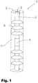
- Fig. 1 represents one embodiment of the measuring head in accordance with the invention
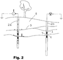
- Fig. 2 represents the principle of mise a la masse when the measuring head in accordance with the invention is used
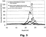
- Fig. 3 represents an example of the measurement results from a measuring arrangement such as the one represented in Fig. 2 .
- Fig. 1 represents a section of a measuring head 1 and a drill hole 2 into which the measuring head is placed.
- the measuring head comprises an elongated body 3, coated in an insulating material, the mid-portion of which body comprises a metallic electrode 4, electroconductively connected via a cable 5 attached to the measuring head and laid inside the body with other measuring equipment (not shown in the figure) on the ground surface.
- the electrical signal can be transmitted via the electrode between the measuring head and its surroundings.
- Three flexible and elastic, thin and plate-like plastic sheets 6 are successively attached to the body of the measuring head on both sides of the electrode.
- the size of the sheets is so adapted that the diameter of each sheet, when in free position, is slightly larger than that of the drill hole.
- the plastic sheets function as electrical insulators, forming around the electrode, along the length of the hole, a measuring area 7, electrically insulated from other parts of the drill hole.
- the insulated measuring area delimits thus the area in which an electrical signal may be transmitted between the electrode and its surroundings. This means that both when feeding the signal via the electrode and when using it as a receiving signal detector, the areal resolution of the electrode improves substantially when compared to the solutions of the prior art, which do not form an electrically insulated measuring area. This improvement in resolution is illustrated in Fig. 2 .
- Both sides of the electrode comprise three insulating sheets, because one insulating sheet is not necessarily capable of insulating the measuring area efficiently enough in all circumstances.
- the sheets 6 curve mutually in the same direction along the length of the body of the measuring head. This facilitates the movement of the measuring head in one direction in the drill hole, and the pressure of the sheets against the wall of the hole as the measuring head is moved in the other direction in the hole.
- curving is directed toward the lower end of the measuring head.
- the direction may as well be the opposite, as in Fig. 2 .
- the curving direction depends for example on whether the measurements are intended to be conducted first at the lower end of the hole and thereafter by lifting the measuring head stepwise in the hole, or the other way round.
- Fig. 2 illustrates the efficiency of the invention in mise a la masse.
- Two drill holes 2a, 2b are drilled in rocky soil 8.
- the soil comprises clefts 9 which are typically filled with water and therefore conduct electricity.
- the principle of mise a la masse is to feed electric current I into the conductive underground area via the drill hole, and to measure the voltage from the other holes.
- An area which has good conductivity is substantially detected in voltage measurements as an area of constant potential, outside which the potential changes all the more radically as the electrical conductivity in the surroundings of the area decreases. This allows the determination of size and shape of the conductive areas, such as rock clefts or ore deposits, and further of their conductivity.
- Fig. 1 illustrates the efficiency of the invention in mise a la masse.
- the electric current when feeding electric current into the drill hole 2a, possibly filled with water, by means of a traditional measuring head, the electric current may flow both up- and downwards in the hole filled with water in accordance with the arrows indicated in dashed line in the figure, and further into all clefts 9, within the ratios defined by their conductivities.
- prospecting for conductive areas by means of measuring the voltage from the other holes 2b such areas would be detected by every cleft, and it would not necessarily be possible to determine, even by the intensity of the voltage, which of the areas would be in direct contact with the cleft nearest to the electrode feeding the current.
- the coverage areas of both current supply and voltage measurement can be delimited in such a way that the measuring resolution improves substantially.
- the current for example, cannot flow out of the measuring area 7 in the drill hole 2a.
- This enables the detection from the potential measurement hole, by means of measuring the voltage, of the exact cleft which is positioned by the measuring area of the electrode feeding the current.
- a similar improvement in resolution when compared to the measuring heads in accordance with the prior art is also detected for example in SPR conducted by one electrode.
- Fig. 3 The measurement results of Fig. 3 were obtained in an arrangement in which a current electrode was placed in one hole by a rock cleft, formed at the depth of 23,6m, and the potential measurement electrode was being moved in the other hole.
- the figure shows the results of the potential measurement electrode at the electrode depths of 10 - 30m. Measurements were conducted using arrangements in which the insulating rubber sheets in accordance with the invention were not used, in which the insulating sheets were used only around the potential measurement electrode, and in which the insulating sheets were installed in both measuring heads. The insulating sheets were used as stacks of four successive sheets.
Landscapes
- Life Sciences & Earth Sciences (AREA)
- Engineering & Computer Science (AREA)
- Environmental & Geological Engineering (AREA)
- Geology (AREA)
- Remote Sensing (AREA)
- Physics & Mathematics (AREA)
- General Life Sciences & Earth Sciences (AREA)
- General Physics & Mathematics (AREA)
- Geophysics (AREA)
- Investigating Or Analyzing Materials By The Use Of Electric Means (AREA)
- Geophysics And Detection Of Objects (AREA)
Claims (5)
- Tête de mesure (1) pour une utilisation dans des mesures électriques conduites dans des trous (2, 2a, 2b) creusés dans le sol (8), comprenant un corps allongé (3), pouvant s'adapter dans le trou, lequel corps comprend une électrode (4), connectant électriquement la tête de mesure avec ses alentours, pour transmettre un signal électrique entre la tête de mesure et ses alentours, dans laquelle la tête de mesure (1) comprend des moyens d'isolation (6) placés sur le corps (3) des deux côtés de l'électrode (4) suivant la longueur du trou (2, 2a, 2b) afin de former une zone de mesure (7), isolée électriquement d'autres parties du trou, autour de l'électrode placée dans le trou ; caractérisée en ce que
les moyens d'isolation (6) sont des feuilles d'isolation de type plaque, flexibles et élastiques agencées autour du corps (3) et dans laquelle les bords des feuilles flexibles sont adaptés pour être appuyés contre les parois du trou (2, 2a, 2b). - Tête de mesure (1) selon la revendication 1, caractérisée en ce que les feuilles d'isolation (6) se courbent dans une direction suivant la longueur du corps (3), de sorte qu'elles suivent le mouvement de la tête de mesure dans le trou (2, 2a, 2b) dans une direction, et sont alors appuyées de façon plus serrée contre les parois du trou du fait du mouvement de la tête de mesure dans la direction opposée.
- Tête de mesure (1) selon la revendication 1 ou 2, caractérisée en ce que, pour augmenter l'efficacité de l'isolation de la zone de mesure (7), au moins deux feuilles d'isolation (6) sont placées successivement des deux côtés de l'électrode (4) suivant la longueur du corps (3).
- Tête de mesure (1) selon l'une quelconque des revendications précédentes, caractérisée en ce que les moyens d'isolation (6) sont agencés pour se déplacer suivant la longueur du corps (3) pour régler la longueur de la zone de mesure (7), agencée autour de l'électrode (4) et isolée électriquement d'autres parties du trou (2, 2a, 2b).
- Procédé de mesure pour une utilisation dans des mesures électriques conduites dans des trous (2, 2a, 2b) creusés dans le sol, procédé dans lequel un signal électrique (I, U) est transmis entre l'électrode (4) placée dans le trou et ses alentours, dans lequel les alentours de l'électrode (4) sont isolés électriquement d'autres parties du trou, suivant la longueur du trou (2, 2a, 2b), caractérisé par l'utilisation de moyens d'isolation (6) qui sont des feuilles d'isolation de type plaque, flexibles et élastiques et dans lequel les bords des feuilles flexibles sont adaptés pour être appuyés contre les parois du trou (2, 2a, 2b).
Applications Claiming Priority (2)
| Application Number | Priority Date | Filing Date | Title |
|---|---|---|---|
| FI20060812A FI120324B (fi) | 2006-09-12 | 2006-09-12 | Virtausmittari |
| PCT/FI2007/000122 WO2008031914A1 (fr) | 2006-09-12 | 2007-05-08 | Tête de mesure et procédé de mesure |
Publications (3)
| Publication Number | Publication Date |
|---|---|
| EP2062060A1 EP2062060A1 (fr) | 2009-05-27 |
| EP2062060A4 EP2062060A4 (fr) | 2017-07-26 |
| EP2062060B1 true EP2062060B1 (fr) | 2020-01-08 |
Family
ID=39654519
Family Applications (1)
| Application Number | Title | Priority Date | Filing Date |
|---|---|---|---|
| EP07730591.0A Active EP2062060B1 (fr) | 2006-09-12 | 2007-05-08 | Tête de mesure et procédé de mesure |
Country Status (5)
| Country | Link |
|---|---|
| US (1) | US8330465B2 (fr) |
| EP (1) | EP2062060B1 (fr) |
| JP (1) | JP5484056B2 (fr) |
| CA (1) | CA2662742C (fr) |
| WO (1) | WO2008031914A1 (fr) |
Families Citing this family (2)
| Publication number | Priority date | Publication date | Assignee | Title |
|---|---|---|---|---|
| JP5565751B2 (ja) * | 2010-06-03 | 2014-08-06 | 株式会社大林組 | 岩盤内の水みち検出システム及び方法 |
| US10082592B2 (en) * | 2015-09-01 | 2018-09-25 | Sondex Wireline Limited | Resistivity imager with reduced borehole loading |
Family Cites Families (29)
| Publication number | Priority date | Publication date | Assignee | Title |
|---|---|---|---|---|
| US2669689A (en) * | 1945-04-13 | 1954-02-16 | Schlumberger Well Surv Corp | Method and apparatus for determining earth for mation factors |
| US2712629A (en) * | 1951-03-07 | 1955-07-05 | Schlumberger Well Surv Corp | Electrical logging of earth formations traversed by a bore hole |
| US2874347A (en) | 1954-11-02 | 1959-02-17 | Gulf Research Development Co | Electric logging |
| US2852734A (en) * | 1957-04-24 | 1958-09-16 | Union Oil Co | Groundwater direction determination |
| US3521154A (en) | 1967-07-03 | 1970-07-21 | Schlumberger Technology Corp | Methods and apparatus for enhancing well logging signals by the use of multiple measurements of the same formation characteristic |
| US3882376A (en) | 1972-04-24 | 1975-05-06 | Schlumberger Technology Corp | Methods and apparatus for investigating earth formations |
| FR2592426B1 (fr) | 1985-12-30 | 1988-04-08 | Inst Francais Du Petrole | Dispositif et procede pour determiner l'orientation de fractures dans une formation geologique |
| JPH0641986B2 (ja) * | 1986-02-27 | 1994-06-01 | 大成基礎設計株式会社 | 地下水の微流速および流向測定法 |
| US4786874A (en) * | 1986-08-20 | 1988-11-22 | Teleco Oilfield Services Inc. | Resistivity sensor for generating asymmetrical current field and method of using the same |
| US5103178A (en) * | 1990-09-11 | 1992-04-07 | Louisiana State University And Agricultural And Mechanical College | Method using a pluraliyt of electrode, including a reference electrode, for recording a spontaneous potential curve in a borehole while drilling |
| US5200705A (en) * | 1991-10-31 | 1993-04-06 | Schlumberger Technology Corporation | Dipmeter apparatus and method using transducer array having longitudinally spaced transducers |
| JP2554969B2 (ja) | 1991-12-09 | 1996-11-20 | 強化土エンジニヤリング株式会社 | 土質調査方法および装置 |
| US6581455B1 (en) * | 1995-03-31 | 2003-06-24 | Baker Hughes Incorporated | Modified formation testing apparatus with borehole grippers and method of formation testing |
| DE69626633T2 (de) * | 1996-01-12 | 2003-09-18 | Posiva Oy, Helsinki | Durchflussmesser |
| JP3551602B2 (ja) | 1996-02-19 | 2004-08-11 | 前田建設工業株式会社 | ボーリング孔漏水位置測定方法及び測定装置 |
| JPH09257950A (ja) | 1996-03-21 | 1997-10-03 | Toho Chisui Kk | 地下水流測定方法とその装置 |
| US5892460A (en) * | 1997-03-06 | 1999-04-06 | Halliburton Energy Services, Inc. | Logging while drilling tool with azimuthal sensistivity |
| US6025722A (en) * | 1997-03-07 | 2000-02-15 | Western Atlas International, Inc. | Azimuthally segmented resistivity measuring apparatus and method |
| US5831156A (en) | 1997-03-12 | 1998-11-03 | Mullins; Albert Augustus | Downhole system for well control and operation |
| JPH10268061A (ja) | 1997-03-26 | 1998-10-09 | Koa Kaihatsu Kk | 地盤比抵抗測定センサ |
| JP4163358B2 (ja) * | 2000-01-13 | 2008-10-08 | 東邦地水株式会社 | 地下水流測定装置 |
| US6633164B2 (en) | 2000-01-24 | 2003-10-14 | Shell Oil Company | Measuring focused through-casing resistivity using induction chokes and also using well casing as the formation contact electrodes |
| US6359438B1 (en) * | 2000-01-28 | 2002-03-19 | Halliburton Energy Services, Inc. | Multi-depth focused resistivity imaging tool for logging while drilling applications |
| JP4276367B2 (ja) * | 2000-10-03 | 2009-06-10 | 鹿島建設株式会社 | 高圧高温流体の流向および流速計測方法および装置 |
| US7109719B2 (en) * | 2004-05-11 | 2006-09-19 | Baker Hughes Incorporated | Method and apparatus for azimuthal resistivity measurements in a borehole |
| US7302841B2 (en) * | 2005-01-11 | 2007-12-04 | Estes James D | Free point tool with low mass sensor |
| US8130117B2 (en) * | 2006-03-23 | 2012-03-06 | Schlumberger Technology Corporation | Drill bit with an electrically isolated transmitter |
| CA2652624C (fr) * | 2006-06-19 | 2013-09-03 | Halliburton Energy Services, Inc. | Ouverture d'antenne dans un tube de fond de puits |
| FI120324B (fi) * | 2006-09-12 | 2009-09-15 | Posiva Oy | Virtausmittari |
-
2007
- 2007-05-08 EP EP07730591.0A patent/EP2062060B1/fr active Active
- 2007-05-08 CA CA2662742A patent/CA2662742C/fr active Active
- 2007-05-08 US US12/440,771 patent/US8330465B2/en not_active Expired - Fee Related
- 2007-05-08 JP JP2009527164A patent/JP5484056B2/ja not_active Expired - Fee Related
- 2007-05-08 WO PCT/FI2007/000122 patent/WO2008031914A1/fr not_active Ceased
Non-Patent Citations (1)
| Title |
|---|
| None * |
Also Published As
| Publication number | Publication date |
|---|---|
| JP2010502972A (ja) | 2010-01-28 |
| CA2662742C (fr) | 2015-08-04 |
| US20100013488A1 (en) | 2010-01-21 |
| JP5484056B2 (ja) | 2014-05-07 |
| WO2008031914A1 (fr) | 2008-03-20 |
| EP2062060A4 (fr) | 2017-07-26 |
| US8330465B2 (en) | 2012-12-11 |
| CA2662742A1 (fr) | 2008-03-20 |
| EP2062060A1 (fr) | 2009-05-27 |
Similar Documents
| Publication | Publication Date | Title |
|---|---|---|
| US7066282B2 (en) | Apparatus and methods for measuring formation characteristics in presence of conductive and non-conductive muds | |
| US9500762B2 (en) | Borehole resistivity imager using discrete energy pulsing | |
| US20220299671A1 (en) | Concealed mineral resource prediction method and logging system based on petro-electromagnetism | |
| WO2005062909A2 (fr) | Imageur multimode de boue a l'huile | |
| CN102628357A (zh) | 一种测井用数据处理设备 | |
| US20130099808A1 (en) | Fluid resistivity sensor | |
| KR101975600B1 (ko) | 지반 측정용 콘 관입장치 | |
| WO2007120072A1 (fr) | Procédé de diagraphie électrique de puits de forage | |
| CN102498418B (zh) | 用于原始矿床地电勘探的传感器设备和方法 | |
| CN102720484A (zh) | 一种随钻声波测井仪器及测井方法 | |
| US8330465B2 (en) | Measuring head and measuring method | |
| KR101324102B1 (ko) | 전기 비저항 탐사용 접지전극 | |
| CN1349614A (zh) | 套管井所穿过的地层的电阻率的测定方法和装置 | |
| US7106076B2 (en) | Device for the simultaneous application of electrical signals and measurement of the electrical potential in a sample | |
| CN203097871U (zh) | 用于测井仪器的极板电极系和用于测井仪器的极板组件 | |
| KR101380699B1 (ko) | 측정 헤드 및 측정 방법 | |
| CN211422629U (zh) | 一种井下油藏监测仪 | |
| CN103643946A (zh) | 一种随钻双电参数测井仪器 | |
| US9423524B2 (en) | Oil-based mud imager with a line source | |
| KR20030042607A (ko) | 전기비저항 탐사 방법 및 장치 | |
| US20190071958A1 (en) | Apparatus and Method of Focused In-Situ Electrical Heating of Hydrocarbon Bearing Formations | |
| CN214660114U (zh) | 微球极板及微球聚焦测井仪 | |
| CA2524728C (fr) | Systeme pour mesurer la resistivite d'une formation terrestre au travers d'un tubage de puits conduisant l'electricite | |
| CN204333225U (zh) | 一种钻井用地层电阻率测量天线 | |
| CN119466739B (zh) | 一种油基泥浆随钻电成像测井装置和方法 |
Legal Events
| Date | Code | Title | Description |
|---|---|---|---|
| PUAI | Public reference made under article 153(3) epc to a published international application that has entered the european phase |
Free format text: ORIGINAL CODE: 0009012 |
|
| 17P | Request for examination filed |
Effective date: 20090312 |
|
| AK | Designated contracting states |
Kind code of ref document: A1 Designated state(s): AT BE BG CH CY CZ DE DK EE ES FI FR GB GR HU IE IS IT LI LT LU LV MC MT NL PL PT RO SE SI SK TR |
|
| AX | Request for extension of the european patent |
Extension state: AL BA HR MK RS |
|
| DAX | Request for extension of the european patent (deleted) | ||
| RA4 | Supplementary search report drawn up and despatched (corrected) |
Effective date: 20170623 |
|
| RIC1 | Information provided on ipc code assigned before grant |
Ipc: G01V 3/20 20060101AFI20170619BHEP |
|
| REG | Reference to a national code |
Ref country code: DE Ref legal event code: R079 Ref document number: 602007059723 Country of ref document: DE Free format text: PREVIOUS MAIN CLASS: G01R0027000000 Ipc: G01V0003200000 |
|
| GRAP | Despatch of communication of intention to grant a patent |
Free format text: ORIGINAL CODE: EPIDOSNIGR1 |
|
| STAA | Information on the status of an ep patent application or granted ep patent |
Free format text: STATUS: GRANT OF PATENT IS INTENDED |
|
| RIC1 | Information provided on ipc code assigned before grant |
Ipc: G01V 3/20 20060101AFI20190814BHEP |
|
| INTG | Intention to grant announced |
Effective date: 20190828 |
|
| RIN1 | Information on inventor provided before grant (corrected) |
Inventor name: HAUTOJAERVI, AIMO Inventor name: ROUHIAINEN, PEKKA Inventor name: AHOKAS, TURO |
|
| GRAS | Grant fee paid |
Free format text: ORIGINAL CODE: EPIDOSNIGR3 |
|
| GRAA | (expected) grant |
Free format text: ORIGINAL CODE: 0009210 |
|
| STAA | Information on the status of an ep patent application or granted ep patent |
Free format text: STATUS: THE PATENT HAS BEEN GRANTED |
|
| AK | Designated contracting states |
Kind code of ref document: B1 Designated state(s): AT BE BG CH CY CZ DE DK EE ES FI FR GB GR HU IE IS IT LI LT LU LV MC MT NL PL PT RO SE SI SK TR |
|
| RAP1 | Party data changed (applicant data changed or rights of an application transferred) |
Owner name: POSIVA OY |
|
| REG | Reference to a national code |
Ref country code: GB Ref legal event code: FG4D |
|
| REG | Reference to a national code |
Ref country code: CH Ref legal event code: EP |
|
| REG | Reference to a national code |
Ref country code: DE Ref legal event code: R096 Ref document number: 602007059723 Country of ref document: DE |
|
| REG | Reference to a national code |
Ref country code: IE Ref legal event code: FG4D |
|
| REG | Reference to a national code |
Ref country code: AT Ref legal event code: REF Ref document number: 1223390 Country of ref document: AT Kind code of ref document: T Effective date: 20200215 |
|
| REG | Reference to a national code |
Ref country code: CH Ref legal event code: NV Representative=s name: ARNOLD AND SIEDSMA AG, CH |
|
| REG | Reference to a national code |
Ref country code: FI Ref legal event code: FGE |
|
| REG | Reference to a national code |
Ref country code: SE Ref legal event code: TRGR |
|
| REG | Reference to a national code |
Ref country code: NL Ref legal event code: MP Effective date: 20200108 |
|
| REG | Reference to a national code |
Ref country code: LT Ref legal event code: MG4D |
|
| PG25 | Lapsed in a contracting state [announced via postgrant information from national office to epo] |
Ref country code: LT Free format text: LAPSE BECAUSE OF FAILURE TO SUBMIT A TRANSLATION OF THE DESCRIPTION OR TO PAY THE FEE WITHIN THE PRESCRIBED TIME-LIMIT Effective date: 20200108 Ref country code: NL Free format text: LAPSE BECAUSE OF FAILURE TO SUBMIT A TRANSLATION OF THE DESCRIPTION OR TO PAY THE FEE WITHIN THE PRESCRIBED TIME-LIMIT Effective date: 20200108 Ref country code: PT Free format text: LAPSE BECAUSE OF FAILURE TO SUBMIT A TRANSLATION OF THE DESCRIPTION OR TO PAY THE FEE WITHIN THE PRESCRIBED TIME-LIMIT Effective date: 20200531 |
|
| PG25 | Lapsed in a contracting state [announced via postgrant information from national office to epo] |
Ref country code: LV Free format text: LAPSE BECAUSE OF FAILURE TO SUBMIT A TRANSLATION OF THE DESCRIPTION OR TO PAY THE FEE WITHIN THE PRESCRIBED TIME-LIMIT Effective date: 20200108 Ref country code: GR Free format text: LAPSE BECAUSE OF FAILURE TO SUBMIT A TRANSLATION OF THE DESCRIPTION OR TO PAY THE FEE WITHIN THE PRESCRIBED TIME-LIMIT Effective date: 20200409 Ref country code: IS Free format text: LAPSE BECAUSE OF FAILURE TO SUBMIT A TRANSLATION OF THE DESCRIPTION OR TO PAY THE FEE WITHIN THE PRESCRIBED TIME-LIMIT Effective date: 20200508 Ref country code: BG Free format text: LAPSE BECAUSE OF FAILURE TO SUBMIT A TRANSLATION OF THE DESCRIPTION OR TO PAY THE FEE WITHIN THE PRESCRIBED TIME-LIMIT Effective date: 20200408 |
|
| REG | Reference to a national code |
Ref country code: DE Ref legal event code: R097 Ref document number: 602007059723 Country of ref document: DE |
|
| PG25 | Lapsed in a contracting state [announced via postgrant information from national office to epo] |
Ref country code: RO Free format text: LAPSE BECAUSE OF FAILURE TO SUBMIT A TRANSLATION OF THE DESCRIPTION OR TO PAY THE FEE WITHIN THE PRESCRIBED TIME-LIMIT Effective date: 20200108 Ref country code: ES Free format text: LAPSE BECAUSE OF FAILURE TO SUBMIT A TRANSLATION OF THE DESCRIPTION OR TO PAY THE FEE WITHIN THE PRESCRIBED TIME-LIMIT Effective date: 20200108 Ref country code: DK Free format text: LAPSE BECAUSE OF FAILURE TO SUBMIT A TRANSLATION OF THE DESCRIPTION OR TO PAY THE FEE WITHIN THE PRESCRIBED TIME-LIMIT Effective date: 20200108 Ref country code: EE Free format text: LAPSE BECAUSE OF FAILURE TO SUBMIT A TRANSLATION OF THE DESCRIPTION OR TO PAY THE FEE WITHIN THE PRESCRIBED TIME-LIMIT Effective date: 20200108 Ref country code: SK Free format text: LAPSE BECAUSE OF FAILURE TO SUBMIT A TRANSLATION OF THE DESCRIPTION OR TO PAY THE FEE WITHIN THE PRESCRIBED TIME-LIMIT Effective date: 20200108 |
|
| PLBE | No opposition filed within time limit |
Free format text: ORIGINAL CODE: 0009261 |
|
| STAA | Information on the status of an ep patent application or granted ep patent |
Free format text: STATUS: NO OPPOSITION FILED WITHIN TIME LIMIT |
|
| REG | Reference to a national code |
Ref country code: AT Ref legal event code: MK05 Ref document number: 1223390 Country of ref document: AT Kind code of ref document: T Effective date: 20200108 |
|
| 26N | No opposition filed |
Effective date: 20201009 |
|
| PG25 | Lapsed in a contracting state [announced via postgrant information from national office to epo] |
Ref country code: AT Free format text: LAPSE BECAUSE OF FAILURE TO SUBMIT A TRANSLATION OF THE DESCRIPTION OR TO PAY THE FEE WITHIN THE PRESCRIBED TIME-LIMIT Effective date: 20200108 Ref country code: MC Free format text: LAPSE BECAUSE OF FAILURE TO SUBMIT A TRANSLATION OF THE DESCRIPTION OR TO PAY THE FEE WITHIN THE PRESCRIBED TIME-LIMIT Effective date: 20200108 Ref country code: IT Free format text: LAPSE BECAUSE OF FAILURE TO SUBMIT A TRANSLATION OF THE DESCRIPTION OR TO PAY THE FEE WITHIN THE PRESCRIBED TIME-LIMIT Effective date: 20200108 |
|
| PG25 | Lapsed in a contracting state [announced via postgrant information from national office to epo] |
Ref country code: PL Free format text: LAPSE BECAUSE OF FAILURE TO SUBMIT A TRANSLATION OF THE DESCRIPTION OR TO PAY THE FEE WITHIN THE PRESCRIBED TIME-LIMIT Effective date: 20200108 Ref country code: SI Free format text: LAPSE BECAUSE OF FAILURE TO SUBMIT A TRANSLATION OF THE DESCRIPTION OR TO PAY THE FEE WITHIN THE PRESCRIBED TIME-LIMIT Effective date: 20200108 |
|
| REG | Reference to a national code |
Ref country code: BE Ref legal event code: MM Effective date: 20200531 |
|
| PG25 | Lapsed in a contracting state [announced via postgrant information from national office to epo] |
Ref country code: LU Free format text: LAPSE BECAUSE OF NON-PAYMENT OF DUE FEES Effective date: 20200508 |
|
| PG25 | Lapsed in a contracting state [announced via postgrant information from national office to epo] |
Ref country code: IE Free format text: LAPSE BECAUSE OF NON-PAYMENT OF DUE FEES Effective date: 20200508 |
|
| PG25 | Lapsed in a contracting state [announced via postgrant information from national office to epo] |
Ref country code: BE Free format text: LAPSE BECAUSE OF NON-PAYMENT OF DUE FEES Effective date: 20200531 |
|
| PG25 | Lapsed in a contracting state [announced via postgrant information from national office to epo] |
Ref country code: TR Free format text: LAPSE BECAUSE OF FAILURE TO SUBMIT A TRANSLATION OF THE DESCRIPTION OR TO PAY THE FEE WITHIN THE PRESCRIBED TIME-LIMIT Effective date: 20200108 Ref country code: MT Free format text: LAPSE BECAUSE OF FAILURE TO SUBMIT A TRANSLATION OF THE DESCRIPTION OR TO PAY THE FEE WITHIN THE PRESCRIBED TIME-LIMIT Effective date: 20200108 Ref country code: CY Free format text: LAPSE BECAUSE OF FAILURE TO SUBMIT A TRANSLATION OF THE DESCRIPTION OR TO PAY THE FEE WITHIN THE PRESCRIBED TIME-LIMIT Effective date: 20200108 |
|
| PGFP | Annual fee paid to national office [announced via postgrant information from national office to epo] |
Ref country code: FR Payment date: 20230516 Year of fee payment: 17 Ref country code: DE Payment date: 20230524 Year of fee payment: 17 Ref country code: CZ Payment date: 20230419 Year of fee payment: 17 Ref country code: CH Payment date: 20230602 Year of fee payment: 17 |
|
| PGFP | Annual fee paid to national office [announced via postgrant information from national office to epo] |
Ref country code: SE Payment date: 20230516 Year of fee payment: 17 Ref country code: FI Payment date: 20230512 Year of fee payment: 17 |
|
| PGFP | Annual fee paid to national office [announced via postgrant information from national office to epo] |
Ref country code: GB Payment date: 20230523 Year of fee payment: 17 |
|
| REG | Reference to a national code |
Ref country code: DE Ref legal event code: R119 Ref document number: 602007059723 Country of ref document: DE |
|
| REG | Reference to a national code |
Ref country code: CH Ref legal event code: PL |
|
| REG | Reference to a national code |
Ref country code: SE Ref legal event code: EUG |
|
| PG25 | Lapsed in a contracting state [announced via postgrant information from national office to epo] |
Ref country code: FI Free format text: LAPSE BECAUSE OF NON-PAYMENT OF DUE FEES Effective date: 20240508 |
|
| PG25 | Lapsed in a contracting state [announced via postgrant information from national office to epo] |
Ref country code: CZ Free format text: LAPSE BECAUSE OF NON-PAYMENT OF DUE FEES Effective date: 20240508 |
|
| GBPC | Gb: european patent ceased through non-payment of renewal fee |
Effective date: 20240508 |
|
| PG25 | Lapsed in a contracting state [announced via postgrant information from national office to epo] |
Ref country code: FI Free format text: LAPSE BECAUSE OF NON-PAYMENT OF DUE FEES Effective date: 20240508 Ref country code: CZ Free format text: LAPSE BECAUSE OF NON-PAYMENT OF DUE FEES Effective date: 20240508 Ref country code: CH Free format text: LAPSE BECAUSE OF NON-PAYMENT OF DUE FEES Effective date: 20240531 |
|
| PG25 | Lapsed in a contracting state [announced via postgrant information from national office to epo] |
Ref country code: DE Free format text: LAPSE BECAUSE OF NON-PAYMENT OF DUE FEES Effective date: 20241203 |
|
| PG25 | Lapsed in a contracting state [announced via postgrant information from national office to epo] |
Ref country code: FR Free format text: LAPSE BECAUSE OF NON-PAYMENT OF DUE FEES Effective date: 20240531 |
|
| PG25 | Lapsed in a contracting state [announced via postgrant information from national office to epo] |
Ref country code: GB Free format text: LAPSE BECAUSE OF NON-PAYMENT OF DUE FEES Effective date: 20240508 |
|
| PG25 | Lapsed in a contracting state [announced via postgrant information from national office to epo] |
Ref country code: SE Free format text: LAPSE BECAUSE OF NON-PAYMENT OF DUE FEES Effective date: 20240509 |