EP2062472A1 - Werkzeughalter, der das Ausweichen eines Hindernisses in einer Reihe ermöglicht - Google Patents
Werkzeughalter, der das Ausweichen eines Hindernisses in einer Reihe ermöglicht Download PDFInfo
- Publication number
- EP2062472A1 EP2062472A1 EP08305836A EP08305836A EP2062472A1 EP 2062472 A1 EP2062472 A1 EP 2062472A1 EP 08305836 A EP08305836 A EP 08305836A EP 08305836 A EP08305836 A EP 08305836A EP 2062472 A1 EP2062472 A1 EP 2062472A1
- Authority
- EP
- European Patent Office
- Prior art keywords
- tool
- axis
- arm
- support
- rotation
- Prior art date
- Legal status (The legal status is an assumption and is not a legal conclusion. Google has not performed a legal analysis and makes no representation as to the accuracy of the status listed.)
- Granted
Links
Images


Classifications
-
- A—HUMAN NECESSITIES
- A01—AGRICULTURE; FORESTRY; ANIMAL HUSBANDRY; HUNTING; TRAPPING; FISHING
- A01B—SOIL WORKING IN AGRICULTURE OR FORESTRY; PARTS, DETAILS, OR ACCESSORIES OF AGRICULTURAL MACHINES OR IMPLEMENTS, IN GENERAL
- A01B39/00—Machines specially adapted for working soil on which crops are growing
- A01B39/12—Machines specially adapted for working soil on which crops are growing for special purposes, e.g. for special culture
- A01B39/16—Machines specially adapted for working soil on which crops are growing for special purposes, e.g. for special culture for working in vineyards, orchards, or the like
Definitions
- the present invention relates to a tool support for the avoidance of an obstacle in a row. It also relates to a device for automatically regulating the working depth of the ground of a tool, more particularly adapted to the tool holder of the invention for a decavaillonneuse.
- a decavaillonneuse comprises a share which returns the earth on a shallow depth between the vines of the same rank in particular to perform a weeding mechanical type.
- a decavaillonneuse is reported on a chassis towed by a motorized vehicle or carried directly by the motorized vehicle.
- the first solution is to connect the share to a first side of a deformable parallelogram in a plane substantially parallel to the ground.
- Reminder means are provided to maintain the parallelogram in a so-called working position.
- a rod is secured to one of the sides of said parallelogram, in particular opposite to that supporting the tool, said rod being able to bear against the feet in order to cause deformation of said parallelogram against the biasing means and the spacing of the tool of the row axis.
- the tool support comprises a feeler likely to take contact with the feet, a sensor capable of detecting a movement of the probe when it comes into contact with a foot and a hydraulic actuator capable of ensuring the movement of the tool between a so-called working position at the axis of the row and an avoidance position, the tool being away from the row axis.
- the tool support comprises a deformable parallelogram in a plane substantially parallel to the ground, the tool being integral with one side of said parallelogram.
- the body of the hydraulic actuator is linked to one side and its stem to another side.
- a double acting distributor is provided, a first state of the distributor corresponding to the output rod and a second state to the retracted rod.
- the probe is movable relative to the support and maintained in a first position by means of return. When the probe comes into contact with an obstacle (foot or stake), it moves slightly against the return means.
- This weak movement is detected by the sensor which informs the distributor which then changes state causing the displacement of the rod, the deformation of the parallelogram and the spacing of the tool from the row axis.
- the return means cause the movement of said probe to the rest position.
- This weak movement is detected by the sensor which informs the distributor which then changes state causing the displacement of the rod, the deformation of the parallelogram and the return of the tool at the row axis.
- the hydraulic actuator is of rotary type and the tool is connected to an arm pivotable through said actuator so as to move the tool away from the row axis.
- the support comprises a probe, a sensor and a double-acting distributor.
- the documents FR-1362750 , FR-2104685 and FR-2290828 describe decavaillonnates each comprising a deformable parallelogram whose deformation is controlled by a pneumatic type actuator.
- the solutions proposed by these documents are not satisfactory because the arrangement of the deformable parallelogram and the actuator does not allow an optimization of the support in terms of actuator power and space.
- the quality depends essentially on the regularity of the working depth of the tool.
- the ploughshare or blade must work the ground to a height of about 5 cm. If the working depth is not sufficient, the roots of the vegetation remain in the unworked soil so that the vegetation resumes quickly. In the opposite case, if the working depth is excessive, the roots of the vegetation are returned with too much soil not allowing them to dry so that the vegetation also resumes quickly.
- the working height must be regulated precisely.
- the working depth of the tool should be regularly adjusted along the row.
- the quality of the weeding is related to the dexterity of the user which is not satisfactory.
- a plow is connected to the tractor via a three-point hitch comprising a lifting device.
- means are provided for measuring the force of the tool on the lifting device and adjust its height according to the measured effort which must oscillate in a range of values. If the measured force exceeds the maximum value of the range, a command is sent to raise the tilt system and reduce the working depth of the plow shares. Otherwise, if the measured force is less than the minimum value of the range then a control is transmitted to lower the lifting system and increase the working depth of the coulters of the plow.
- this solution does not allow to regulate optimally the working depth in the case of a decavaillonneuse, the measurement of the force being disturbed during the avoidance of the feet in particular by the weight and the inertia of the frame in movement.
- each element of the drill can pivot about a horizontal axis and comprises a follower roller provided for rolling on the ground.
- the roller follows the terrain and eventually rotates the element around the horizontal axis so that the seeds are arranged substantially at the same depth.
- each element comprises a frame supporting several tools, with the front and rear wheels in contact with the ground mounted on arms mounted to pivot relative to the frame.
- An actuator is provided on each arm to rotate and adjust the height of the frame relative to the ground.
- Sensors are provided to determine the position of each arm and inform a central unit that controls according to the difference in position of the arms of the various elements actuators to adjust the position of the elements together.
- the present invention aims to overcome the disadvantages of the prior art by providing a tool support, more particularly adapted to a decavaillonneuse, to optimize the power required and the quality of work.
- the subject of the invention is a tool support capable of translating in a direction substantially parallel to a row, so as to maintain a tool in line with the axis of said row between obstacles, said support comprising a first arm, a second arm whose first end is articulated along a first axis of rotation at a first distal end of the first arm, a third arm to which is connected the tool, a first end is articulated along a second axis of rotation substantially parallel to the first axis at the second end of the second arm and a fourth arm whose first end is articulated along a third axis of rotation substantially parallel to the first axis at the second end of the third arm and whose second end is articulated along a fourth axis of rotation substantially parallel to the first axis at a second end of first arm, said support being capable of occupying a first state in which the tool is disposed at the row axis and a second state in which the tool is spaced apart from the row axis, said support also comprising means for
- the dotted line has a dotted line 10 comprising obstacles 12 such as feet or stakes.
- a tool support 14 to which is connected a tool 16, such as a share in the illustrated example.
- a tool 16 such as a share
- the tool support according to the invention may be suitable for other tools (such as a blade inter ceps for example) and other types of culture.
- the tool support 14 is capable of translating in a direction (shown by the arrows in the figures) substantially parallel to said rows 10 so as to maintain the tool at the axis of the row between the obstacles.
- the tool support 14 can be fixed on a machine connected to a motorized machine such as a tractor or directly attached to a motorized machine.
- the tool support optionally comprises a first part 18 ensuring the avoidance of the obstacles 12 and possibly a second part ensuring the automatic regulation of the working depth of the tool 16.
- This first part 18 comprises a first arm 20 extending in a plane substantially parallel to the ground, a second arm 22 whose first end is articulated along a first axis 24 of rotation substantially perpendicular to the ground at a distal end of the first arm 20, a third arm 26, a first end is articulated along a second axis 28 of rotation substantially parallel to the first axis 24 at the second end of the second arm 22 and a fourth arm 30, a first end is articulated along a third axis 32 of rotation substantially parallel to the first axis 24 at the second end of the third arm 26 and whose second end is articulated along a fourth axis 34 of rotation substantially parallel to the first axis 24 at the first arm 20.
- the four arms 20, 22, 26 and 30 form a deformable quadrilateral.
- the tool 16 is secured to the third arm 26 via a gooseneck 36.
- the tool 16 is disposed at the axis 10 of the row while when in a second configuration, the tool 16 is spaced from the axis of the row 10 as illustrated on the figures 2 and 3 .
- Returning means 38 are provided to maintain the quadrilateral in the first configuration for which the tool 16 is disposed at the axis 10 of the row.
- the return means 38 comprise at least one tension spring.
- a preferably adjustable stop 40 makes it possible to adjust the first configuration.
- one of the movable elements, in particular the second arm 22 comprises an extension 42 capable of bearing against a stop 40 secured to the first arm 20.
- the return means 38 serve to keep the extension 42 pressed against the abutment 40.
- the deformable quadrilateral makes it possible to maintain the orientation of the share during the avoidance, unlike the variant with a single axis of rotation which causes a pivoting of the share.
- the length of the arms between the axes of rotation and / or by adjusting the shape of the gooseneck it is possible to define a particular kinematics of the share during avoidance and reduce the efforts of the tool on the support when working the earth.
- the geometry of the support and / or the return means 38 provide a quasi-balance of efforts when the tool works the ground.
- the shapes of the tool 16 allow a better return of the tool to the first state and helps reduce the power required.
- the first part 18 ensuring the avoidance of obstacles comprises means 44 for detecting an obstacle present in the row.
- These detection means 44 comprise a feeler 46 capable of pivoting about an axis of rotation 48 substantially parallel to the hinge axis 24 and a sensor 50 for detecting the pivoting movement of said probe 46.
- the feeler 46 is held in a first position corresponding to the absence of an obstacle as illustrated in FIGS. figures 1 and 3 by means of return means 52 which come to immobilize it against a stop 53.
- the feeler 46 is held against the stop 53.
- the arrangement and the shapes of the feeler 46 and the tool 16 are such that the tool 16 is set back relative to the feeler 46 during the avoidance and does not protrude to catch the obstacle.
- the detection means 44 while bearing against the stop 53 can assist mechanically modifying the geometry of the tool support, for example if the force of the actuator is not sufficient.
- the detection means 44 ensure the passage of the support in the second state and ensure that the tool 16 is always offset from the obstacle.
- the feeler 46 comprises a first substantially rectilinear portion and a slightly curved rearward end in the direction of movement of the tool, the rectilinear portion being substantially perpendicular to the row axis and the beginning of the curved portion being disposed substantially to the right of the row axis.
- the probe 46 When the probe 46 comes into contact with an obstacle 12, it pivots slightly by an angle ⁇ against the biasing means 52. The sensor 50 in the form of a switch is then actuated by the probe. The hurdle passed, as illustrated on the figure 3 , the probe 46 pivots against the direction by the action of the return means 52 and no longer operates the contactor 50.
- the sensitivity of the detection means 44 is adjustable, more or less taring the return means 52 for example.
- the axis of rotation 48 of the probe 46 is integral with the movable part, and in particular in the illustrated case of the second arm 22. This configuration allows the probe to rotate also during the avoidance which facilitates the passage of the obstacle.
- the invention is not limited to this type of detection means and other solutions could be envisaged for the detection of obstacles.
- the first part 18 ensuring the avoidance of obstacles comprises at least one pneumatic actuator 54 ensuring the movement of at least one moving part to generate the movement of the tool 16 of a first state in which it is positioned at the right of the row axis to a second state in which it is spaced from said row axis to avoid an obstacle, said pneumatic actuator 54 being driven by the detection means.
- the pneumatic solution makes it possible to limit the risks of pollution in case of leakage. Moreover, the fact of using pneumatic energy makes it possible to reduce the necessary powers, which results in a reduction in consumption.
- the pneumatic actuator 54 is of single-acting type and makes it possible to cause only the spacing of the tool from the axis of the row against the return means 38.
- a single chamber of the pneumatic actuator 54 is supplied with compressed air from a source not shown.
- the supply is controlled by a valve 56 which is itself controlled by the detection means 44.
- the means 44 When the means 44 detect an obstacle, as illustrated in FIG. figure 2 , they control the opening of the valve 56 which allows the supply of the pneumatic actuator 54. The latter causes the change of state of the system against the return means 38 which results in the distance of the tool 16 of the row axis. As long as the probe 46 is in contact with the obstacle, the pneumatic actuator 54 is supplied with compressed air and the tool is kept away from the row axis. When the probe 46 is no longer in contact with the obstacle, as shown in FIG. figure 3 , the detection means 44 control the closing of the valve 56 which stops the supply of the pneumatic actuator 54. The latter being no longer supplied, the return means 38 cause the change of state of the system which translates by the return of the tool to the right of the row.
- the return means 38 make it possible to obtain a stable position, which corresponds to the working position when the tool is at the level of the axis 10 of the row. pneumatic actuator allowing the change of state and the holding in the remote position.
- the pneumatic actuator is of double-acting type and allows the maintenance in the stable positions, namely at the level of the row and spaced apart from the rank, as well as the change from one state to another.
- This configuration has the advantage of allowing the user to force the change of state and impose on the tool a return to working position at the row level.
- the pneumatic actuator comprises an adjustable throttle in order to adjust the kinematics of the tool from the position to the right of the row axis at the spaced apart position, the throttle being arranged either at the level of the exhaust or at the admission level.
- the pneumatic energy is more reactive, the energy being stored in a reservoir and released into the actuator.
- a fast movement is obtained at the beginning of the adjustable spacing movement by throttling.
- This configuration limits the risk of plant damage, which is essential for seedlings or for certain crops such as apple trees.
- the actuator 54 is interposed between the first arm 20 and an extension 62 of the second arm, said extension 62 being disposed opposite the second axis of rotation 28 relative to the first axis of rotation 24.
- the first axis of rotation 24 is disposed between the second axis of rotation and the articulation between the actuator 54 and the extension 62.
- This arrangement makes it possible to optimize the power of the actuator by means of a greater lever arm which enables to reduce the effort required to cause the spacing of the tool.
- the actuator 54 is disposed opposite the tool 16 and does not risk interfering with said tool or an element projected by said tool, which contributes to the reliability of the mechanism.
- this configuration allows the assembly to be more compact insofar as the actuator 54 may not be offset in height relative to the parallelogram.
- the body of the actuator 54 comprises an end at which its rod 60 which is pivotally mounted about an axis 58 integral with the first arm 20, the end of the rod 60 being connected to the extension 62.
- This configuration provides a high compactness facilitating the installation of a possible crankcase.
- the position of the axis 58 is determined so as to obtain a constant and significant lever arm over the entire stroke of the actuator rod, particularly at the end of the stroke when the rod is out.
- a disengageable system may be provided at the connection between the tool 16 and the gooseneck 36.
- the end of the gooseneck 36 comprises an axis 64 around which the tool 16 can pivot.
- the disengageable system makes it possible in a first state to block the rotation of the tool 16 around the axis 66. and in a second state said disengaged to allow the rotation of the share.
- the disengaging system may be replaced by a spring or a pneumatic jack interposed between the tool and the gooseneck which immobilizes the tool when the force exerted by the tool 16 on the link does not exceed a certain threshold and which allows the tool to rotate when said force exceeds a certain threshold, preferably adjustable by taring more or less the spring or the cylinder.
- the tool support may comprise a second portion 66 providing automatic control of the working depth of the tool 16 illustrated in detail on the figure 5 .
- This second part hereinafter referred to as a regulating device 66, comprises a part 68 connected directly or indirectly to a motorized machine and a movable part 70 connected to the tool, according to the illustrated example an upright 70 connected to the first arm 20 of the part ensuring the avoidance of obstacles.
- a hinge 72 is provided between the parts 68 and 70 to allow movement in a plane substantially vertical or perpendicular to the ground of the tool 16 relative to the motorized machine and adjust its working depth.
- this articulation is in the form of a deformable parallelogram, two rods 74 providing the connection between the fixed part 68 and the mobile part 70.
- the parallelogram makes it possible to obtain a variation in the height of the tool without changing its orientation or without influencing the movements of the tool during the avoidance of an obstacle.
- An actuator 76 is provided for deforming the articulation 72.
- the actuator can be interposed between a link 74 and the fixed part 68.
- the actuator 76 is in the form of a jack, for example of the electric or hydraulic type.
- the regulation device 66 comprises means 86 for measuring at least one resultant of the ground reaction force on the tool 16 arranged at the tool support 14 as well as means 88 controlled by the measuring means 86 and controlling the articulation 72, in particular the actuator 76, in order to modify, if necessary, the depth of the tool 16.
- Each tool whose working depth is regulated comprises an articulation and measuring means 86 dedicated thereto.
- unique control can control several tools at a time.
- each tool working the ground comprises measuring means 86 which optimizes the regulation of the working depth of the tools that are individually regulated.
- the measuring means are carried by the tool support and are not offset relative to the tool, such as a follower roller of the prior art, the presence of the regulating device does not increase the range. of unworked ground around the foot during the avoidance.
- the measuring means 86 are arranged at the joint 72. This arrangement makes it possible to move the measuring means 86 away from the active zone of the tool and limits the risk of damaging said measuring means 86.
- the measuring means 86 make it possible to measure a deformation of the articulation, at least one resultant of the reaction force of the ground on the tool tending to deform the articulation 72.
- a pressure sensor can be used as measuring means 86 when the actuator 76 is of hydraulic type and used to measure at least one resultant of the ground reaction force on the tool tending to deform the joint.
- one of the rods 74 is replaced by a hydraulic type cylinder and a pressure sensor is used as a measuring means 86 of at least one resultant of the ground reaction force on the tool tending to deform the articulation.
- the tool support 14 comprises at least two joints, a first articulation 72 making it possible to modify the depth of the tool 16, for example a deformable parallelogram, and a second articulation 90 making it possible to measure at least one resultant of the force of ground reaction on the tool.
- This second articulation 90 is more particularly disposed between the first articulation 72 and the tool 16.
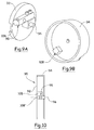
- the second hinge 90 comprises a fixed part 92 connected to a motorized machine or to a chassis connected to a motorized machine and a movable part 94 secured to the tool 16, the two parts 92 and 94 being movable relative to one another. another according to a pivot axis 96 substantially parallel to the ground and perpendicular to the advance movement.
- the first part 92 is connected to the post 70 of the first joint and the second part 94 is connected to the first arm 20 of the obstacle avoidance part.
- the ground reaction force on the tool or at least one of its results leads to a relative movement of the two parts 92 and 94.
- Measuring means 86 are interposed between the two parts 92 and 94 so as to quantify this relative movement which is substantially proportional to the ground reaction force on the tool 16.
- the measuring means 86 are in the form of of a strain gauge 98.
- Means are provided for limiting this relative rotational movement between the two parts over an angular range of the order of a few fractions of a degree so that the measuring means 86 work on an optimum range, particularly in the case of a strain gauge.
- the first part 92 is in the form of an amount supporting a pivot axis 96.
- the second portion 94 is in the form of a yoke with at one end of the bearing surfaces rotatably mounted on the axis 96 and at a second end a sheath 100 in which can be inserted an amount supporting the tool 16.
- a strain gauge 98 is interposed between the sheath 100 and the first portion 92.
- a first portion 102 of the strain gauge 98 is integral with the amount of the first portion 92 while a second portion 102 'is connected to the sleeve 100.
- a stop 104 makes it possible to limit the rotational movement in a first direction and a second stop 106 makes it possible to limit the rotational movement in the other direction.
- these two stops are adjustable in order to adjust the angular range of rotation between the two parts 92 and 94.
- the parts 92 and 94 are each in the form of a disc pivoting about the same pivot axis 96, the two discs being slightly spaced and one of them comprising a cylindrical peripheral wall so as to define a cavity in which are placed the measuring means 86 to protect them.
- Stoppers are provided to limit the relative rotational movement between the two parts 92 and 94.
- a strain gauge 98 is interposed between the two projecting portions 92 and 94 so as to quantify the relative movement between said two parts 92 and 94 and thus the ground reaction force on the tool.
- the strain gauge 98 comprises a first part 108 integral with the first disc 92 and a second part 108 'integral with the second disc 94.
- the operating principle of the regulating device of the invention is as follows:
- control means 88 tend to modify the depth of the tool by controlling the articulation 72 and more particularly the actuator 76 or another articulation.
- the difference can be either positive or negative, which in fact translates into an excessive or insufficient soil working depth.
- the ground reaction force is measured on the tool every second for each tool.
- the values of three consecutive measurements are averaged.
- This average is stored in order to be compared with a predetermined set value for each tool.
- control means 88 control the modification of the depth of the tool.
- the duration of the control pulse of the actuator responsible for modifying the depth of the tool depends on the one hand on the difference between the average and the value of the setpoint and on the other hand on a constant of adjusting the predetermined reactivity by the user, the duration of the pulse being equal to the difference divided by the adjustment constant.
- each tool is independently corrected with a set value or depth that is specific to it and that may be different from one tool to another.
- the tools can work at a controlled depth that is different from one tool to another.
- a first tool can work at a first depth which corresponds to a set point of 20 with a tolerance of +/- 5.
- the value measured by the means 86 can oscillate in a range from to 25 without the control means 88 change the depth of the tool.
- a second tool may have a setpoint and / or correction tolerance identical or different from the first tool.
- the user can program a depth identical to the two tools but with a shift depending on the tilt.
- the device comprises a command making it possible to adjust the offset with respect to an average depth that makes it possible to assign an offset of a certain value, for example +2, to a first tool located at the top of the devers and an offset of an opposite value, for example -2, to a second tool located at the bottom of the slope.
- an offset of a certain value for example +2
- an offset of an opposite value for example -2
- the value measured at a first tool can vary from 13 to 23 whereas the value measured at the second tool can vary from 17 to 27.
- the regulating device 66 comprises means 86 for measuring at least one resultant of the ground reaction force on the tool 16 disposed at the tool support 14 as well as the control means 88 indicated by the measuring means 86 and controlling the articulation 72 so as to modify the depth of the tool 16 if necessary.
- the means 86 are in the form of a pressure sensor for measuring the pressure of the hydraulic fluid delivered to the hydraulic motor rotating the rotary tool. This pressure being substantially proportional to the working depth, it is possible from its measurement to regulate the depth of the tool.
- the tool support comprises means 86 for measuring at least one resultant of the ground reaction force on the tool and control means 88 regulating the position of the tool in function. the difference between the measured value and a set value.
- the tool support comprises at least one hinge whose deformation makes it possible to quantify the reaction force of the ground on the tool.
- This articulation can be combined with another articulation to modify the depth of the tool that can be integrated into the support or independent of the support.
- unique control means can make it possible to regulate several tools each supported by a tool support according to the invention comprising at least one hinge equipped with measuring means 86.
Landscapes
- Life Sciences & Earth Sciences (AREA)
- Engineering & Computer Science (AREA)
- Mechanical Engineering (AREA)
- Soil Sciences (AREA)
- Environmental Sciences (AREA)
- Jib Cranes (AREA)
- Manipulator (AREA)
- Forklifts And Lifting Vehicles (AREA)
- Agricultural Machines (AREA)
- Cutting Tools, Boring Holders, And Turrets (AREA)
- Road Signs Or Road Markings (AREA)
- Soil Working Implements (AREA)
Applications Claiming Priority (2)
| Application Number | Priority Date | Filing Date | Title |
|---|---|---|---|
| FR0759301A FR2923980A1 (fr) | 2007-11-26 | 2007-11-26 | Support d'outil permettant l'evitement d'un obstacle dans un rang |
| FR0854493A FR2933268B1 (fr) | 2008-07-02 | 2008-07-02 | Dispositif pour reguler automatiquement la profondeur de travail du sol d'un outil. |
Publications (2)
| Publication Number | Publication Date |
|---|---|
| EP2062472A1 true EP2062472A1 (de) | 2009-05-27 |
| EP2062472B1 EP2062472B1 (de) | 2011-04-13 |
Family
ID=40261023
Family Applications (1)
| Application Number | Title | Priority Date | Filing Date |
|---|---|---|---|
| EP08305836A Active EP2062472B1 (de) | 2007-11-26 | 2008-11-25 | Werkzeughalter, der das Ausweichen eines Hindernisses in einer Reihe ermöglicht |
Country Status (3)
| Country | Link |
|---|---|
| EP (1) | EP2062472B1 (de) |
| AT (1) | ATE505072T1 (de) |
| DE (1) | DE602008006150D1 (de) |
Cited By (7)
| Publication number | Priority date | Publication date | Assignee | Title |
|---|---|---|---|---|
| ITPD20120337A1 (it) * | 2012-11-09 | 2014-05-10 | Angelo Busolin | Macchina automatica per diradatura o zappatura/arieggiatura del terreno interposto fra una pianta e l'altra di una coltivazione di ortaggi a filare. |
| FR3012285A1 (fr) * | 2013-10-25 | 2015-05-01 | Sarl Jean Michel Egretier | Procede d'actionnement d'un outil porte par un porte-outil inter-plants et porte-outil pour sa mise en oeuvre |
| FR3066879A1 (fr) * | 2017-06-06 | 2018-12-07 | Ferrand | Procede de pilotage d'un support d'outil equipe d'un systeme d'evitement d'obstacles et support d'outil configure pour la mise en œuvre du procede |
| EP3824708A1 (de) * | 2019-11-25 | 2021-05-26 | Rinieri S.r.l. | Zwischenreihenmaschine |
| EP4052550A1 (de) * | 2021-03-05 | 2022-09-07 | Clemens GmbH & Co. KG, Weinbautechnik - Getränketechnik | Seitenhangausgleichsvorrichtung für den weinanbau |
| EP4052551A1 (de) * | 2021-03-05 | 2022-09-07 | Clemens GmbH & Co. KG, Weinbautechnik - Getränketechnik | Landwirtschaftliche maschine mit einem bodenbearbeitungswerkzeug und verfahren zur steuerung eines bodenbearbeitungswerkzeuges |
| EP4406393A1 (de) | 2023-01-17 | 2024-07-31 | Industrias David S.L.U. | Vorrichtung zur zwischenreihenkultivierung von holzartigem erntegut |
Citations (7)
| Publication number | Priority date | Publication date | Assignee | Title |
|---|---|---|---|---|
| FR1362750A (fr) | 1963-05-14 | 1964-06-05 | Décavaillonneuse à commandes pneumatiques | |
| FR2104685A2 (de) | 1970-07-08 | 1972-04-21 | Larrouquere Louis | |
| FR2290828A1 (fr) | 1974-11-13 | 1976-06-11 | Egretier M | Perfectionnements a la commande des charrues decavaillonneuses et outils agricoles analogues |
| DE9114640U1 (de) * | 1991-11-25 | 1992-01-23 | Clemens Und Co Kg, 5560 Wittlich | An ein landwirtschaftliches Fahrzeug o.dgl. anbaubare Vorrichtung zur Bodenbearbeitung |
| US5957218A (en) | 1997-11-18 | 1999-09-28 | Deere & Company | Electrohydraulic control of implement lift cylinders |
| US6701857B1 (en) * | 2003-01-16 | 2004-03-09 | Lynn David Jensen | Depth control device for planting implement |
| CA2549371A1 (en) * | 2006-05-23 | 2007-11-23 | William R. Ritchie | A ground opening device |
-
2008
- 2008-11-25 EP EP08305836A patent/EP2062472B1/de active Active
- 2008-11-25 DE DE602008006150T patent/DE602008006150D1/de active Active
- 2008-11-25 AT AT08305836T patent/ATE505072T1/de not_active IP Right Cessation
Patent Citations (7)
| Publication number | Priority date | Publication date | Assignee | Title |
|---|---|---|---|---|
| FR1362750A (fr) | 1963-05-14 | 1964-06-05 | Décavaillonneuse à commandes pneumatiques | |
| FR2104685A2 (de) | 1970-07-08 | 1972-04-21 | Larrouquere Louis | |
| FR2290828A1 (fr) | 1974-11-13 | 1976-06-11 | Egretier M | Perfectionnements a la commande des charrues decavaillonneuses et outils agricoles analogues |
| DE9114640U1 (de) * | 1991-11-25 | 1992-01-23 | Clemens Und Co Kg, 5560 Wittlich | An ein landwirtschaftliches Fahrzeug o.dgl. anbaubare Vorrichtung zur Bodenbearbeitung |
| US5957218A (en) | 1997-11-18 | 1999-09-28 | Deere & Company | Electrohydraulic control of implement lift cylinders |
| US6701857B1 (en) * | 2003-01-16 | 2004-03-09 | Lynn David Jensen | Depth control device for planting implement |
| CA2549371A1 (en) * | 2006-05-23 | 2007-11-23 | William R. Ritchie | A ground opening device |
Cited By (11)
| Publication number | Priority date | Publication date | Assignee | Title |
|---|---|---|---|---|
| ITPD20120337A1 (it) * | 2012-11-09 | 2014-05-10 | Angelo Busolin | Macchina automatica per diradatura o zappatura/arieggiatura del terreno interposto fra una pianta e l'altra di una coltivazione di ortaggi a filare. |
| FR3012285A1 (fr) * | 2013-10-25 | 2015-05-01 | Sarl Jean Michel Egretier | Procede d'actionnement d'un outil porte par un porte-outil inter-plants et porte-outil pour sa mise en oeuvre |
| FR3012284A1 (fr) * | 2013-10-25 | 2015-05-01 | Sarl Jean Michel Egretier | Porte-outil inter-plants oscillant |
| ES2534705R1 (es) * | 2013-10-25 | 2015-11-23 | Sarl Jean Michel Egretier | Procedimiento de accionamiento de una herramienta portada por un portaherramientas entre plantas y portaherramientas para su puesta en práctica |
| FR3066879A1 (fr) * | 2017-06-06 | 2018-12-07 | Ferrand | Procede de pilotage d'un support d'outil equipe d'un systeme d'evitement d'obstacles et support d'outil configure pour la mise en œuvre du procede |
| EP3412123A1 (de) * | 2017-06-06 | 2018-12-12 | Ferrand | Verfahren zur steuerung eines werkzeugträgers, der mit einem hindernisvermeidungssystem ausgestattet ist, und werkzeugträger, der für die umsetzung dieses verfahrens konfiguriert ist |
| EP3824708A1 (de) * | 2019-11-25 | 2021-05-26 | Rinieri S.r.l. | Zwischenreihenmaschine |
| US11839169B2 (en) | 2019-11-25 | 2023-12-12 | Rinieri S.R.L. | Inter-row machine |
| EP4052550A1 (de) * | 2021-03-05 | 2022-09-07 | Clemens GmbH & Co. KG, Weinbautechnik - Getränketechnik | Seitenhangausgleichsvorrichtung für den weinanbau |
| EP4052551A1 (de) * | 2021-03-05 | 2022-09-07 | Clemens GmbH & Co. KG, Weinbautechnik - Getränketechnik | Landwirtschaftliche maschine mit einem bodenbearbeitungswerkzeug und verfahren zur steuerung eines bodenbearbeitungswerkzeuges |
| EP4406393A1 (de) | 2023-01-17 | 2024-07-31 | Industrias David S.L.U. | Vorrichtung zur zwischenreihenkultivierung von holzartigem erntegut |
Also Published As
| Publication number | Publication date |
|---|---|
| DE602008006150D1 (de) | 2011-05-26 |
| EP2062472B1 (de) | 2011-04-13 |
| ATE505072T1 (de) | 2011-04-15 |
Similar Documents
| Publication | Publication Date | Title |
|---|---|---|
| EP2062472B1 (de) | Werkzeughalter, der das Ausweichen eines Hindernisses in einer Reihe ermöglicht | |
| CA2226656C (fr) | Machine agricole de coupe perfectionnee | |
| EP2839731B1 (de) | Futtererntemaschine | |
| EP1705980B1 (de) | Scheiben-schälpflug für bodenbearbeitungsmaschine | |
| EP3834592B1 (de) | Pflug mit mindestens einer zusätzlichen bodenbearbeitungseinrichtung | |
| EP2818036A1 (de) | Erntemaschine | |
| EP0876748A1 (de) | Maschine mit einer relativ zu der Tragkonstruktion schwenkbaren Bearbeitungseinheit und Schwenk-Verfahren | |
| EP1976367B2 (de) | Bodenbearbeitungsmaschine in der art eines vertikalscheibenpfluges | |
| FR2944410A1 (fr) | Dispositif agricole de travail du sol | |
| FR2904181A1 (fr) | Machine agricole, notamment semoir semi-porte | |
| FR3023448A1 (fr) | Dispositif apte a se deplacer le long d'un rang de culture et integrant au moins un porte-outil flottant | |
| FR2923980A1 (fr) | Support d'outil permettant l'evitement d'un obstacle dans un rang | |
| FR2933268A1 (fr) | Dispositif pour reguler automatiquement la profondeur de travail du sol d'un outil. | |
| CA3044243A1 (fr) | Machine de fenaison avec largeur de projection controlee | |
| EP4460172B1 (de) | Vorrichtung und system zur schnittstelle zwischen einer landwirtschaftlichen traktorkupplung und einem arbeitsgerät | |
| FR3121319A1 (fr) | Ensemble de travail du sol et machine de travail du sol comprenant un tel ensemble | |
| FR3111513A1 (fr) | Machine agricole comportant au moins un dispositif de traitement des végétaux et/ou du sol | |
| FR2551941A1 (fr) | Tracteur muni d'un dispositif de levage avant perfectionne | |
| FR3164345A1 (fr) | Procédé de correction de la dérive d’une machine agricole attelée à l’arrière d’un véhicule tracteur et une telle machine agricole permettant sa mise œuvre | |
| EP2880969B1 (de) | Bodenauflockerungsvorrichtung, die zum Ziehen bestimmt ist und ein verformbares Parallelogramm umfasst, das mit mindestens einem Auflockerungselement ausgestattet ist | |
| EP4374674A1 (de) | Verfahren zur kontrolle und steuerung von mindestens einer zusätzlichen arbeitsvorrichtung, mit der ein drehpflug ausgerüstet ist, und ein solcher drehpflug | |
| FR3002109A3 (fr) | Machine interceps pour le travail de la terre | |
| EP3022996B1 (de) | Landwirtschaftliche maschine mit einer umschaltvorrichtung mit winkelerfassung | |
| EP4706357A1 (de) | Schleppvorrichtung mit einem verformbaren parallelogramm, das mindestens ein hackelement trägt | |
| FR2800972A1 (fr) | Dispositif de fauchage des vegetaux |
Legal Events
| Date | Code | Title | Description |
|---|---|---|---|
| PUAI | Public reference made under article 153(3) epc to a published international application that has entered the european phase |
Free format text: ORIGINAL CODE: 0009012 |
|
| AK | Designated contracting states |
Kind code of ref document: A1 Designated state(s): AT BE BG CH CY CZ DE DK EE ES FI FR GB GR HR HU IE IS IT LI LT LU LV MC MT NL NO PL PT RO SE SI SK TR |
|
| AX | Request for extension of the european patent |
Extension state: AL BA MK RS |
|
| 17P | Request for examination filed |
Effective date: 20091027 |
|
| 17Q | First examination report despatched |
Effective date: 20091120 |
|
| AKX | Designation fees paid |
Designated state(s): AT BE BG CH CY CZ DE DK EE ES FI FR GB GR HR HU IE IS IT LI LT LU LV MC MT NL NO PL PT RO SE SI SK TR |
|
| GRAP | Despatch of communication of intention to grant a patent |
Free format text: ORIGINAL CODE: EPIDOSNIGR1 |
|
| GRAS | Grant fee paid |
Free format text: ORIGINAL CODE: EPIDOSNIGR3 |
|
| GRAA | (expected) grant |
Free format text: ORIGINAL CODE: 0009210 |
|
| AK | Designated contracting states |
Kind code of ref document: B1 Designated state(s): AT BE BG CH CY CZ DE DK EE ES FI FR GB GR HR HU IE IS IT LI LT LU LV MC MT NL NO PL PT RO SE SI SK TR |
|
| REG | Reference to a national code |
Ref country code: GB Ref legal event code: FG4D Free format text: NOT ENGLISH |
|
| REG | Reference to a national code |
Ref country code: CH Ref legal event code: EP |
|
| REG | Reference to a national code |
Ref country code: IE Ref legal event code: FG4D Free format text: LANGUAGE OF EP DOCUMENT: FRENCH |
|
| REF | Corresponds to: |
Ref document number: 602008006150 Country of ref document: DE Date of ref document: 20110526 Kind code of ref document: P |
|
| REG | Reference to a national code |
Ref country code: DE Ref legal event code: R096 Ref document number: 602008006150 Country of ref document: DE Effective date: 20110526 |
|
| REG | Reference to a national code |
Ref country code: NL Ref legal event code: VDEP Effective date: 20110413 |
|
| REG | Reference to a national code |
Ref country code: CH Ref legal event code: NV Representative=s name: BUGNION S.A. |
|
| REG | Reference to a national code |
Ref country code: ES Ref legal event code: FG2A Ref document number: 2364996 Country of ref document: ES Kind code of ref document: T3 Effective date: 20110920 |
|
| LTIE | Lt: invalidation of european patent or patent extension |
Effective date: 20110413 |
|
| PG25 | Lapsed in a contracting state [announced via postgrant information from national office to epo] |
Ref country code: LT Free format text: LAPSE BECAUSE OF FAILURE TO SUBMIT A TRANSLATION OF THE DESCRIPTION OR TO PAY THE FEE WITHIN THE PRESCRIBED TIME-LIMIT Effective date: 20110413 Ref country code: NO Free format text: LAPSE BECAUSE OF FAILURE TO SUBMIT A TRANSLATION OF THE DESCRIPTION OR TO PAY THE FEE WITHIN THE PRESCRIBED TIME-LIMIT Effective date: 20110713 Ref country code: HR Free format text: LAPSE BECAUSE OF FAILURE TO SUBMIT A TRANSLATION OF THE DESCRIPTION OR TO PAY THE FEE WITHIN THE PRESCRIBED TIME-LIMIT Effective date: 20110413 Ref country code: SE Free format text: LAPSE BECAUSE OF FAILURE TO SUBMIT A TRANSLATION OF THE DESCRIPTION OR TO PAY THE FEE WITHIN THE PRESCRIBED TIME-LIMIT Effective date: 20110413 Ref country code: PT Free format text: LAPSE BECAUSE OF FAILURE TO SUBMIT A TRANSLATION OF THE DESCRIPTION OR TO PAY THE FEE WITHIN THE PRESCRIBED TIME-LIMIT Effective date: 20110816 |
|
| REG | Reference to a national code |
Ref country code: IE Ref legal event code: FD4D |
|
| PG25 | Lapsed in a contracting state [announced via postgrant information from national office to epo] |
Ref country code: GR Free format text: LAPSE BECAUSE OF FAILURE TO SUBMIT A TRANSLATION OF THE DESCRIPTION OR TO PAY THE FEE WITHIN THE PRESCRIBED TIME-LIMIT Effective date: 20110714 Ref country code: CY Free format text: LAPSE BECAUSE OF FAILURE TO SUBMIT A TRANSLATION OF THE DESCRIPTION OR TO PAY THE FEE WITHIN THE PRESCRIBED TIME-LIMIT Effective date: 20110413 Ref country code: SI Free format text: LAPSE BECAUSE OF FAILURE TO SUBMIT A TRANSLATION OF THE DESCRIPTION OR TO PAY THE FEE WITHIN THE PRESCRIBED TIME-LIMIT Effective date: 20110413 Ref country code: LV Free format text: LAPSE BECAUSE OF FAILURE TO SUBMIT A TRANSLATION OF THE DESCRIPTION OR TO PAY THE FEE WITHIN THE PRESCRIBED TIME-LIMIT Effective date: 20110413 Ref country code: AT Free format text: LAPSE BECAUSE OF FAILURE TO SUBMIT A TRANSLATION OF THE DESCRIPTION OR TO PAY THE FEE WITHIN THE PRESCRIBED TIME-LIMIT Effective date: 20110413 Ref country code: FI Free format text: LAPSE BECAUSE OF FAILURE TO SUBMIT A TRANSLATION OF THE DESCRIPTION OR TO PAY THE FEE WITHIN THE PRESCRIBED TIME-LIMIT Effective date: 20110413 Ref country code: IS Free format text: LAPSE BECAUSE OF FAILURE TO SUBMIT A TRANSLATION OF THE DESCRIPTION OR TO PAY THE FEE WITHIN THE PRESCRIBED TIME-LIMIT Effective date: 20110813 |
|
| PG25 | Lapsed in a contracting state [announced via postgrant information from national office to epo] |
Ref country code: NL Free format text: LAPSE BECAUSE OF FAILURE TO SUBMIT A TRANSLATION OF THE DESCRIPTION OR TO PAY THE FEE WITHIN THE PRESCRIBED TIME-LIMIT Effective date: 20110413 |
|
| PG25 | Lapsed in a contracting state [announced via postgrant information from national office to epo] |
Ref country code: IE Free format text: LAPSE BECAUSE OF FAILURE TO SUBMIT A TRANSLATION OF THE DESCRIPTION OR TO PAY THE FEE WITHIN THE PRESCRIBED TIME-LIMIT Effective date: 20110413 Ref country code: EE Free format text: LAPSE BECAUSE OF FAILURE TO SUBMIT A TRANSLATION OF THE DESCRIPTION OR TO PAY THE FEE WITHIN THE PRESCRIBED TIME-LIMIT Effective date: 20110413 Ref country code: CZ Free format text: LAPSE BECAUSE OF FAILURE TO SUBMIT A TRANSLATION OF THE DESCRIPTION OR TO PAY THE FEE WITHIN THE PRESCRIBED TIME-LIMIT Effective date: 20110413 |
|
| PLBE | No opposition filed within time limit |
Free format text: ORIGINAL CODE: 0009261 |
|
| STAA | Information on the status of an ep patent application or granted ep patent |
Free format text: STATUS: NO OPPOSITION FILED WITHIN TIME LIMIT |
|
| PG25 | Lapsed in a contracting state [announced via postgrant information from national office to epo] |
Ref country code: SK Free format text: LAPSE BECAUSE OF FAILURE TO SUBMIT A TRANSLATION OF THE DESCRIPTION OR TO PAY THE FEE WITHIN THE PRESCRIBED TIME-LIMIT Effective date: 20110413 Ref country code: PL Free format text: LAPSE BECAUSE OF FAILURE TO SUBMIT A TRANSLATION OF THE DESCRIPTION OR TO PAY THE FEE WITHIN THE PRESCRIBED TIME-LIMIT Effective date: 20110413 Ref country code: DK Free format text: LAPSE BECAUSE OF FAILURE TO SUBMIT A TRANSLATION OF THE DESCRIPTION OR TO PAY THE FEE WITHIN THE PRESCRIBED TIME-LIMIT Effective date: 20110413 Ref country code: RO Free format text: LAPSE BECAUSE OF FAILURE TO SUBMIT A TRANSLATION OF THE DESCRIPTION OR TO PAY THE FEE WITHIN THE PRESCRIBED TIME-LIMIT Effective date: 20110413 |
|
| 26N | No opposition filed |
Effective date: 20120116 |
|
| REG | Reference to a national code |
Ref country code: DE Ref legal event code: R097 Ref document number: 602008006150 Country of ref document: DE Effective date: 20120116 |
|
| BERE | Be: lapsed |
Owner name: SOUSLIKOFF ET CIE Effective date: 20111130 |
|
| PG25 | Lapsed in a contracting state [announced via postgrant information from national office to epo] |
Ref country code: MC Free format text: LAPSE BECAUSE OF NON-PAYMENT OF DUE FEES Effective date: 20111130 |
|
| PG25 | Lapsed in a contracting state [announced via postgrant information from national office to epo] |
Ref country code: BE Free format text: LAPSE BECAUSE OF NON-PAYMENT OF DUE FEES Effective date: 20111130 |
|
| REG | Reference to a national code |
Ref country code: DE Ref legal event code: R082 Ref document number: 602008006150 Country of ref document: DE Representative=s name: REISER & PARTNER PATENTANWAELTE, DE Ref country code: DE Ref legal event code: R082 Ref document number: 602008006150 Country of ref document: DE Representative=s name: REISER & PARTNER PATENTANWAELTE MBB, DE |
|
| PG25 | Lapsed in a contracting state [announced via postgrant information from national office to epo] |
Ref country code: MT Free format text: LAPSE BECAUSE OF FAILURE TO SUBMIT A TRANSLATION OF THE DESCRIPTION OR TO PAY THE FEE WITHIN THE PRESCRIBED TIME-LIMIT Effective date: 20110413 |
|
| PG25 | Lapsed in a contracting state [announced via postgrant information from national office to epo] |
Ref country code: LU Free format text: LAPSE BECAUSE OF NON-PAYMENT OF DUE FEES Effective date: 20111125 |
|
| PG25 | Lapsed in a contracting state [announced via postgrant information from national office to epo] |
Ref country code: BG Free format text: LAPSE BECAUSE OF FAILURE TO SUBMIT A TRANSLATION OF THE DESCRIPTION OR TO PAY THE FEE WITHIN THE PRESCRIBED TIME-LIMIT Effective date: 20110713 |
|
| GBPC | Gb: european patent ceased through non-payment of renewal fee |
Effective date: 20121125 |
|
| PG25 | Lapsed in a contracting state [announced via postgrant information from national office to epo] |
Ref country code: TR Free format text: LAPSE BECAUSE OF FAILURE TO SUBMIT A TRANSLATION OF THE DESCRIPTION OR TO PAY THE FEE WITHIN THE PRESCRIBED TIME-LIMIT Effective date: 20110413 |
|
| PG25 | Lapsed in a contracting state [announced via postgrant information from national office to epo] |
Ref country code: HU Free format text: LAPSE BECAUSE OF FAILURE TO SUBMIT A TRANSLATION OF THE DESCRIPTION OR TO PAY THE FEE WITHIN THE PRESCRIBED TIME-LIMIT Effective date: 20110413 |
|
| PG25 | Lapsed in a contracting state [announced via postgrant information from national office to epo] |
Ref country code: GB Free format text: LAPSE BECAUSE OF NON-PAYMENT OF DUE FEES Effective date: 20121125 |
|
| REG | Reference to a national code |
Ref country code: FR Ref legal event code: PLFP Year of fee payment: 8 |
|
| REG | Reference to a national code |
Ref country code: FR Ref legal event code: PLFP Year of fee payment: 9 |
|
| REG | Reference to a national code |
Ref country code: FR Ref legal event code: PLFP Year of fee payment: 10 |
|
| PGFP | Annual fee paid to national office [announced via postgrant information from national office to epo] |
Ref country code: DE Payment date: 20241119 Year of fee payment: 17 |
|
| PGFP | Annual fee paid to national office [announced via postgrant information from national office to epo] |
Ref country code: IT Payment date: 20241129 Year of fee payment: 17 |
|
| PGFP | Annual fee paid to national office [announced via postgrant information from national office to epo] |
Ref country code: CH Payment date: 20241201 Year of fee payment: 17 |
|
| PGFP | Annual fee paid to national office [announced via postgrant information from national office to epo] |
Ref country code: FR Payment date: 20251119 Year of fee payment: 18 |
|
| PGFP | Annual fee paid to national office [announced via postgrant information from national office to epo] |
Ref country code: ES Payment date: 20251216 Year of fee payment: 18 |