EP2062746A1 - Assemblage de roue et de moyeu - Google Patents
Assemblage de roue et de moyeu Download PDFInfo
- Publication number
- EP2062746A1 EP2062746A1 EP20080152895 EP08152895A EP2062746A1 EP 2062746 A1 EP2062746 A1 EP 2062746A1 EP 20080152895 EP20080152895 EP 20080152895 EP 08152895 A EP08152895 A EP 08152895A EP 2062746 A1 EP2062746 A1 EP 2062746A1
- Authority
- EP
- European Patent Office
- Prior art keywords
- wheel
- sleeve
- retaining member
- pin sleeve
- hub assembly
- Prior art date
- Legal status (The legal status is an assumption and is not a legal conclusion. Google has not performed a legal analysis and makes no representation as to the accuracy of the status listed.)
- Granted
Links
Images








Classifications
-
- B—PERFORMING OPERATIONS; TRANSPORTING
- B60—VEHICLES IN GENERAL
- B60B—VEHICLE WHEELS; CASTORS; AXLES FOR WHEELS OR CASTORS; INCREASING WHEEL ADHESION
- B60B27/00—Hubs
- B60B27/06—Hubs adapted to be fixed on axle
- B60B27/065—Hubs adapted to be fixed on axle characterised by the fixation of the hub to the axle
-
- B—PERFORMING OPERATIONS; TRANSPORTING
- B60—VEHICLES IN GENERAL
- B60B—VEHICLE WHEELS; CASTORS; AXLES FOR WHEELS OR CASTORS; INCREASING WHEEL ADHESION
- B60B27/00—Hubs
-
- B—PERFORMING OPERATIONS; TRANSPORTING
- B60—VEHICLES IN GENERAL
- B60B—VEHICLE WHEELS; CASTORS; AXLES FOR WHEELS OR CASTORS; INCREASING WHEEL ADHESION
- B60B27/00—Hubs
- B60B27/02—Hubs adapted to be rotatably arranged on axle
-
- B—PERFORMING OPERATIONS; TRANSPORTING
- B60—VEHICLES IN GENERAL
- B60B—VEHICLE WHEELS; CASTORS; AXLES FOR WHEELS OR CASTORS; INCREASING WHEEL ADHESION
- B60B37/00—Wheel-axle combinations, e.g. wheel sets
- B60B37/10—Wheel-axle combinations, e.g. wheel sets the wheels being individually rotatable around the axles
-
- B—PERFORMING OPERATIONS; TRANSPORTING
- B60—VEHICLES IN GENERAL
- B60B—VEHICLE WHEELS; CASTORS; AXLES FOR WHEELS OR CASTORS; INCREASING WHEEL ADHESION
- B60B2200/00—Type of product being used or applied
- B60B2200/40—Articles of daily use
- B60B2200/41—Waste bins
-
- B—PERFORMING OPERATIONS; TRANSPORTING
- B60—VEHICLES IN GENERAL
- B60B—VEHICLE WHEELS; CASTORS; AXLES FOR WHEELS OR CASTORS; INCREASING WHEEL ADHESION
- B60B2320/00—Manufacturing or maintenance operations
- B60B2320/10—Assembling; disassembling
-
- B—PERFORMING OPERATIONS; TRANSPORTING
- B60—VEHICLES IN GENERAL
- B60B—VEHICLE WHEELS; CASTORS; AXLES FOR WHEELS OR CASTORS; INCREASING WHEEL ADHESION
- B60B2320/00—Manufacturing or maintenance operations
- B60B2320/50—Securing
-
- B—PERFORMING OPERATIONS; TRANSPORTING
- B60—VEHICLES IN GENERAL
- B60B—VEHICLE WHEELS; CASTORS; AXLES FOR WHEELS OR CASTORS; INCREASING WHEEL ADHESION
- B60B2320/00—Manufacturing or maintenance operations
- B60B2320/50—Securing
- B60B2320/52—Securing to prevent loss
-
- B—PERFORMING OPERATIONS; TRANSPORTING
- B60—VEHICLES IN GENERAL
- B60B—VEHICLE WHEELS; CASTORS; AXLES FOR WHEELS OR CASTORS; INCREASING WHEEL ADHESION
- B60B2360/00—Materials; Physical forms thereof
- B60B2360/30—Synthetic materials
- B60B2360/32—Plastic compositions
-
- B—PERFORMING OPERATIONS; TRANSPORTING
- B60—VEHICLES IN GENERAL
- B60B—VEHICLE WHEELS; CASTORS; AXLES FOR WHEELS OR CASTORS; INCREASING WHEEL ADHESION
- B60B2900/00—Purpose of invention
- B60B2900/20—Avoidance of
- B60B2900/212—Damage
-
- B—PERFORMING OPERATIONS; TRANSPORTING
- B60—VEHICLES IN GENERAL
- B60B—VEHICLE WHEELS; CASTORS; AXLES FOR WHEELS OR CASTORS; INCREASING WHEEL ADHESION
- B60B2900/00—Purpose of invention
- B60B2900/30—Increase in
- B60B2900/331—Safety or security
- B60B2900/3312—Safety or security during regular use
-
- B—PERFORMING OPERATIONS; TRANSPORTING
- B65—CONVEYING; PACKING; STORING; HANDLING THIN OR FILAMENTARY MATERIAL
- B65F—GATHERING OR REMOVAL OF DOMESTIC OR LIKE REFUSE
- B65F1/00—Refuse receptacles; Accessories therefor
- B65F1/14—Other constructional features; Accessories
- B65F1/1468—Means for facilitating the transport of the receptacle, e.g. wheels, rolls
- B65F1/1473—Receptacles having wheels
-
- Y—GENERAL TAGGING OF NEW TECHNOLOGICAL DEVELOPMENTS; GENERAL TAGGING OF CROSS-SECTIONAL TECHNOLOGIES SPANNING OVER SEVERAL SECTIONS OF THE IPC; TECHNICAL SUBJECTS COVERED BY FORMER USPC CROSS-REFERENCE ART COLLECTIONS [XRACs] AND DIGESTS
- Y10—TECHNICAL SUBJECTS COVERED BY FORMER USPC
- Y10T—TECHNICAL SUBJECTS COVERED BY FORMER US CLASSIFICATION
- Y10T29/00—Metal working
- Y10T29/49—Method of mechanical manufacture
- Y10T29/49481—Wheel making
- Y10T29/49492—Land wheel
-
- Y—GENERAL TAGGING OF NEW TECHNOLOGICAL DEVELOPMENTS; GENERAL TAGGING OF CROSS-SECTIONAL TECHNOLOGIES SPANNING OVER SEVERAL SECTIONS OF THE IPC; TECHNICAL SUBJECTS COVERED BY FORMER USPC CROSS-REFERENCE ART COLLECTIONS [XRACs] AND DIGESTS
- Y10—TECHNICAL SUBJECTS COVERED BY FORMER USPC
- Y10T—TECHNICAL SUBJECTS COVERED BY FORMER US CLASSIFICATION
- Y10T29/00—Metal working
- Y10T29/49—Method of mechanical manufacture
- Y10T29/49481—Wheel making
- Y10T29/49492—Land wheel
- Y10T29/49533—Hub making
Definitions
- the present invention generally relates to wheel assemblies and the manner of their mounting to and removal from an axle, and more particularly, to wheel and hub assemblies used on refuse carts and the like.
- plastic wheels on a variety of products has dramatically increased in recent years.
- One area where such plastic wheels have been widely employed is on wheeled refuse or garbage carts or bins of the type commonly employed by homeowners for their trash.
- These carts traditionally have plastic wheels that are mounted on the ends of a metal axle by a hub member or push-on hat fastener (sometimes referred to as "pawl nut").
- the wheel hub is hammered onto the end of the axle to hold the wheel in place. Removal of such plastic wheels in order to replace or repair the wheel or the cart can be difficult because the hammered push-on hat fasteners or hubs require special tools for their removal, or essentially must be destroyed to remove them from the axle. Sometimes this process also damages the axles.
- Wheel-mounting sleeve assemblies have been devised which snap-on to a pre-machined axle to hold the wheel to the axle.
- these snap-on wheel assemblies have been unduly complex, visually unappealing, and poorly suited to the shock loading and vibration commonly encountered.
- the design of certain prior wheel and hub assemblies limits the extent of automatic assembly of a wheel and hub assembly because the pin and spring would be expelled from the wheel assembly without a portion of the wheel to keep them in place.
- the hub assembly may be specifically oriented such that the pin and spring do not fall out until coupling to a wheel.
- manipulation of the hub assembly such as transporting, dropping, turning, and especially vibration caused by automating equipment can cause the pin and spring to become lost before assembly, increasing costs and slowing assembly due to insertion of replacement parts.
- foreign debris can enter the open end of a pin sleeve all the way until assembly with a wheel.
- the pin and spring are generally installed during coupling of the wheel and a hub assembly. Upon disengagement of the wheel from such hub assemblies, which may occur when a wheel assembly is broken (e.g., due to splitting of the wheel from shock loading), the pin and spring can be expelled from the hub assembly to be lost or damaged.
- At least one aspect of the present invention is the realization of the advantages gained from a restraining element such as a plug that prevents the pin and spring from being separated from the hub assembly upon manipulation without being coupled to a wheel.
- a restraining element such as a plug that prevents the pin and spring from being separated from the hub assembly upon manipulation without being coupled to a wheel.
- the plug also allows fully automated assembly because the hub assembly can be oriented in any direction and can be positioned by a vibratory feeder. Moreover, if a wheel is damaged, the hub assembly, which is typically the more expensive component, can be coupled to another wheel because all of its pieces are still in tact and accounted for.
- a wheel assembly comprises a wheel and a hub assembly mounted in the wheel.
- the wheel includes a sleeve bore.
- the hub assembly includes a retainer housing, a retaining member, a biasing element, and a restraining element.
- the retainer housing includes a wheel mounting sleeve and a pin sleeve.
- the wheel mounting sleeve includes an axle bore configured to receive an axle and configured to be inserted within the sleeve bore of the wheel.
- the pin sleeve includes a first end, a second end, and a conduit between the first end and the second end. The first end is in fluid communication with the sleeve bore. The first end includes a shoulder extending into the conduit.
- the retaining member is disposed within the conduit of the pin sleeve.
- the retaining member includes a lip wider than the shoulder. The lip and the shoulder interact to prevent the retaining member from exiting the first end of the pin sleeve.
- the biasing element is disposed within the conduit of the pin sleeve and is configured to bias the retaining member towards the axle bore.
- the retaining member is configured to operatively engage a groove in an axle.
- the restraining element is configured to prevent the retaining member from exiting the second end of the pin sleeve.
- a hub assembly comprises a retainer housing, a retaining member, a biasing element, and a restraining element.
- the retainer housing includes a wheel mounting sleeve and a pin sleeve.
- the wheel mounting sleeve includes an axle bore configured to receive an axle and configured to be inserted within a sleeve bore of a wheel.
- the pin sleeve includes a first end, a second end, and a conduit between the first end and the second end. The first end is in fluid communication with the sleeve bore.
- the first end includes a shoulder extending into the conduit.
- the retaining member is disposed within the conduit of the pin sleeve.
- the retaining member includes a lip wider than the shoulder.
- the lip and the shoulder interact to prevent the retaining member from exiting the first end of the pin sleeve.
- the biasing element is disposed within the conduit of the pin sleeve and is configured to bias the retaining member towards the axle bore.
- the retaining member is configured to operatively engage a groove in an axle.
- the restraining element is configured to prevent the retaining member from exiting the second end of the pin sleeve.
- a method of manufacturing a wheel assembly comprises forming a wheel and forming a retainer housing.
- the wheel includes a sleeve bore.
- Forming the retainer housing includes forming a wheel mounting sleeve and forming a pin sleeve.
- the wheel mounting sleeve includes an axle bore configured to receive an axle and configured to be inserted within the sleeve bore of the wheel.
- the pin sleeve includes a first end, a second end, and a conduit between the first end and the second end. The first end is in fluid communication with the sleeve bore. The first end includes a shoulder extending into the conduit.
- the method further comprises positioning a retaining member within the pin sleeve.
- the retaining member includes a lip wider than the shoulder. The lip and the shoulder interact to prevent the retaining member from exiting the first end of the pin sleeve.
- the method further comprises positioning a biasing element in the pin sleeve to bias the retaining member towards the axle bore.
- the method further comprises occluding the second end of the pin sleeve, thereby preventing the retaining member from exiting the second end of the pin sleeve.
- the method further comprises inserting the wheel mounting sleeve of the retainer housing into the sleeve bore of the wheel, thereby coupling the retainer housing to the wheel.
- Figure 1 is a top perspective view of a refuse cart including a wheel assembly mounted thereto.
- Figure 2A is a top perspective view of a side of an example embodiment of a wheel assembly.
- Figure 2B is a bottom perspective view of another side of the wheel assembly of Figure 2A .
- Figure 3A is a top perspective view of a side of another example embodiment of a wheel assembly.
- Figure 3B is a bottom perspective view of another side of the wheel assembly of Figure 3A .
- Figure 3C is a top perspective cross sectional view of the wheel of the wheel assembly of Figure 3A .
- Figure 4A is a top perspective view of a side of an example embodiment of a hub assembly.
- Figure 4B is a bottom perspective view of another side of the hub assembly of Figure 4A .
- Figure 4C is a cutaway top perspective view of the hub assembly of Figure 4A .
- Figure 4D is a cross-sectional view of the hub assembly of Figures 4A engaged with an axle.
- Figure 5A is a cutaway top perspective view of the wheel assembly of Figure 2A .
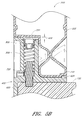
- Figure 5B is a cross-sectional view of the wheel assembly of Figure 2A engaged with an axle.
- Figure 5C is a cutaway top perspective view of the wheel assembly of Figure 3A .
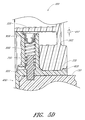
- Figure 5D is a cross-sectional view of the wheel assembly of Figure 3A engaged with an axle.
- Figure 5E is a cross-sectional view of an example embodiment of a wheel assembly engaged with an axle and a cart body.
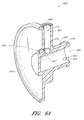
- Figure 6A is a cutaway top perspective view of a side of an example embodiment of a retainer housing.
- Figure 6B is a top perspective view of another side of the retainer housing of Figure 6A .
- Figure 7 is a top perspective view of an example embodiment of a retaining member.
- Figure 8 is a top perspective view of an example embodiment of a biasing element.
- Figure 9A is a top perspective view of an example embodiment of a restraining element.
- Figure 9B is a cross-sectional view of the restraining element of Figure 9A .
- Figure 10A is a top perspective cross-sectional view of another example embodiment of a hub assembly.
- Figure 10B is a top perspective cross-sectional view of still another example embodiment of a hub assembly.
- Figure 10C is a top perspective cross-sectional view of yet another example embodiment of a hub assembly.
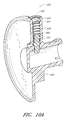
- Figure 10D is a top perspective cross-sectional view of yet still another example embodiment of a hub assembly.
- Figure 1 illustrates an example embodiment of a refuse cart comprising plurality of wheel assemblies 110 mounted on an axle 150 to the lower end of the cart body 102.
- a hinged lid 104 optionally can be provided, and the cart 100 can be tilted or tipped about the wheel assemblies 200 using handle 106 so as to enable rolling of the cart 100 for the transport of refuse, for example between a location for filling the cart 100 and a location for pickup by a refuse disposal company.
- the lower end of the cart body 102 optionally includes a wheel well or recess area 108 configured to receive wheel assemblies 110, for example to protect the wheel assemblies 110 and as a cosmetic structure.
- the wheel assemblies 110 are secured on the axle 150 by a hub assembly 400.
- the wheel assemblies described herein are also suitable for use with other wheeled products such as wagons, wheeled food and beverage coolers, barbecues, wheeled toys, small refuse containers, and the like.
- Figure 2A is a top perspective view of a side of an example embodiment of a wheel assembly 200 (e.g., an "outer" side when the wheel assembly is mounted to a cart 100 via an axle 150).
- Figure 2B is a bottom perspective view of another side of the wheel assembly 200 of Figure 2A (e.g., an "inner” side when the wheel assembly is mounted to a cart 100 via an axle 150).
- a user can generally see the entire outer side of the wheel assembly 200, but a portion of the inner side of the wheel assembly 200 can be at least partially obscured by the lower end of the cart body 102 (e.g., as depicted in Figure 1 ).
- the wheel assembly 200 comprises a wheel 202 and a hub assembly 400 (described below) coupled to (e.g., mounted on) the wheel 202.
- blow molding includes coupling two female mold cavities, extruding molten material (called a "parison"), and expanding the material by blowing air into the parison. After the material has sufficiently hardened, the wheel 202 is removed from the molds.
- treads 204 and spokes 206 are integrally formed during the molding process.
- the treads 204 can help the wheel 202 to frictionally engage a surface during rolling movement and can enhance the appearance of the wheel 202.
- the spokes 206 can help evenly distribute forces acting on the wheel 202.
- Other features of the wheel 202 may also be integrally formed by modifying the mold.
- the blow molding process forms hollow interior surfaces (see Figure 5A ) that can reduce the amount of material used in creation of the wheel 202, but also provide strength by creating certain shapes.
- forming the wheel 202 includes trimming or "deflashing" the wheel 202.
- the wheel 202 is deflashed while in a mold cavity.
- the wheel 202 comprises plastic (e.g., high density polyethylene (HDPE) (e.g., high molecular weight HDPE)).
- HDPE high density polyethylene
- HDPE high molecular weight HDPE
- Figure 3A is a top perspective view of a side of another example embodiment of a wheel assembly 300 (e.g., an "outer" side when the wheel assembly is mounted to a cart 100 via an axle 150).
- Figure 3B is a bottom perspective view of another side of the wheel assembly 300 of Figure 3A (e.g., an "inner” side when the wheel assembly is mounted to a cart 100 via an axle 150).
- a user can generally see the entire outer side of the wheel assembly 300, but a portion of the inner side of the wheel assembly 300 can be at least partially obscured by the lower end of the cart body 102 (e.g., as depicted in Figure 1 ).
- the wheel assembly 300 comprises a wheel 302 and a hub assembly 400 (described below) coupled to (e.g., mounted on) the wheel 302.
- the wheel 302 illustrated in Figures 3A and 3B is injection molded.
- injection molding includes coupling a male mold and a female mold and injecting molten material therebetween. After the material has sufficiently hardened, the wheel 302 is removed from the molds.
- treads 304 and spokes 306 are integrally formed during the molding process.
- the treads 304 can help the wheel 302 to frictionally engage a surface during rolling movement and can enhance the appearance of the wheel 302.
- the spokes 306 can help evenly distribute forces acting on the wheel 302.
- Other features of the wheel 302 may also be integrally formed by modifying the mold.
- the injection molding process can form corrugated and hollow interior surfaces (see Figure 3C ) that can reduce the amount of material used in creation of the wheel 302, but also provide strength by creating certain shapes.
- the wheel 302 comprises plastic (e.g., high density polyethylene (HDPE) (e.g., high molecular weight HDPE)).
- Figure 3B also shows that cavities 308 may be formed under the treads 304, and in some embodiments exposed (e.g., on the inner side of the wheel 302).
- Figure 3C illustrates a cross-sectional view of the wheel 302 of the wheel assembly 300.
- the wheel 302 includes a sleeve bore 310.
- the sleeve bore 310 includes a first end, a second end, and a conduit therebetween. In certain embodiments, one of the ends may be closed.
- the sleeve bore 310 may be centered within the wheel 302 such that an axle 150 inserted into the sleeve bore 310 (e.g., into a hub assembly 400 at least partially disposed within the sleeve bore 310) can uniformly rotate.
- the sleeve bore 310 is configured to receive a wheel mounting sleeve of a hub assembly (e.g., the wheel mounting sleeve 302 of the hub assembly 400).
- the wheel 202 also includes a sleeve bore 210.
- wheel assemblies described herein may comprise wheels manufactured using other processes (e.g., rotational or compression molding) and/or having other features.
- the wheel may have a separate tread attached to the outer surface.
- the wheel may comprise materials such as wood, metal, rubber, combinations thereof, etc.
- Figure 4A is a top perspective view of a side of an example embodiment of a hub assembly 400 (e.g., an "outer" side when the hub assembly 400 is mounted to a wheel that is mounted to a cart 100 via an axle 150).
- Figure 4B is a bottom perspective view of another side of the hub assembly 400 of Figure 4A (e.g., an "inner” side when the hub assembly 400 is mounted to a wheel that is mounted to a cart 100 via an axle 150).
- Figure 4C is a cutaway top perspective view of the hub assembly 400 of Figure 4A , which illustrates some of the inner components of the hub assembly 400.
- the hub assembly 400 comprises a retainer housing 600, a retaining member 700, a biasing element 800, and a restraining element 900.
- the retainer housing 600 includes a wheel mounting sleeve 602 including an axle bore 606 configured to receive an axle 150 and configured to be inserted within the sleeve bore 310 of a wheel 202, 302.
- the retainer housing 600 also includes a pin sleeve 604 including a first end 607, a second end 608, and a conduit 610 between the first end 607 and the second end 608 ( Figures 6A and 6B ).
- the first end 607 includes a shoulder 612 extending into the conduit 610.
- the retaining member 700 is disposed within the conduit 610 of the pin sleeve 604.
- the retaining member 700 includes a lip 704 that is wider than the shoulder 612.
- the lip 704 and the shoulder 612 interact to prevent the retaining member 700 from exiting the first end 607 of the pin sleeve 604.
- the retaining member 700 may be pushed by the biasing element 800 into the axle bore 606, where it may become lost (e.g., by becoming displaced from the hub assembly) or damaged (e.g., by being crushed by the axle 150).
- the biasing element 800 is disposed within the conduit 610 of the pin sleeve 604.
- the biasing element 800 is configured to bias the retaining member 700 towards the axle bore 606 and is configured to operatively engage a groove 152 in an axle 150.
- the restraining element 900 is configured to prevent the retaining member 700 from exiting the second end 608 of the pin sleeve 604.
- Figure 4C is a cutaway top perspective view of the hub assembly 400, which shows the interaction between the elements.
- the biasing element 800 within the pin sleeve 604 is in a relaxed position (i.e., the biasing element 800 only applies force to the retaining member 700 and the restraining element 900 upon being compressed).
- the biasing element 800 within the pin sleeve 604 is in a compressed state such that the biasing element 800 applies force to the retaining member 700 and the restraining element 900 regardless of the position of the retaining member 700.
- the restraining element 900 is stationary, but the retaining member 700 can move longitudinally within the pin sleeve 604 and compress the biasing element 800.
- a portion of the retaining member 700 protrudes through the first end 607 of the pin sleeve 604 and through the wheel mounting sleeve 602 and into the axle bore 606, where it can interact with a groove 152 in an axle 150.
- the axle 150 pushes the retaining member 700 into the pin sleeve 604.
- the retaining member 700 acted upon by the biasing element 800, extends out of the pin sleeve 604 and into the groove 152.
- Figure 4D is a side cross-sectional view of the hub assembly 400 operatively engaged with the groove 152 of an axle 150. Once engaged, the retaining element 700 interacts with the groove 152 to prevent the hub assembly 400 from becoming detached from the axle 150. If a user wishes to detach the hub assembly 400 from the axle 150, a tool may be inserted into the tool passageway 630. A tool inserted through the tool passageway 630 may act on the retaining element 700 to extend it towards the second end 608 of the pin sleeve 604 and out of the axle bore 606, at which point the axle 150 may be slid out of the axle bore 606.
- a tool may act on the lip 704 of the retaining element 700 (e.g., acting as a wedge or lever to cause the retaining element 700 to move). In some embodiments, a tool may pierce or puncture the retaining element 700 such that movement of the tool causes a corresponding movement of the retaining element 700. Other interactions between a tool and the retaining element 700 are also possible (e.g., a tool may fit into a slot of a retaining element 700).
- a membrane (or "puncture skin") 632 may at least partially cover the tool passageway 630.
- the membrane 632 is preferably thin enough to be punctured by the tool prior to engagement with the retaining member 700 (e.g., about 0.01 inch thick).
- the membrane 632 can provide evidence of tampering with the hub assembly 400.
- the membrane 632 may also disguise access to the retaining member 700, such that only a person having knowledge of the hub assembly 400 is able to detach the hub assembly 400 from the axle 150.
- the membrane 632 may be flush with the end wall 614 or elsewhere.
- the tool passageway 630 may be raised with respect to the end wall 614 (e.g., by the lip 634) to identify the tool passageway 630 if covered by a membrane 632 and/or to aid in positioning of the hub assembly 400 into the wheel 202, 302. Additionally, the components of the hub assembly 400 remain together upon intentional or unintentional detachment from a wheel 202, 302, which can prevent the retaining element 700 and/or the biasing element 800 from becoming lost or damaged.
- Certain hub assemblies known in the art leave the second end of the pin sleeve open, which allows the retaining member and/or the biasing element to exit the second end of the pin sleeve when the hub assembly is not coupled to a wheel.
- Such wheel assemblies thus require simultaneous assembly of the components of the hub assembly and attachment of the hub assembly to the wheel.
- damage to the wheel assembly resulting in detachment of the hub assembly from the wheel can cause the components of the hub assembly to exit the pin sleeve, whereupon they may be lost and/or damaged.
- the restraining element 900 of certain embodiments of the present invention can prevent the retaining member 700 and/or the biasing element 800 from exiting the second end 608 of the pin sleeve 604.
- the components of the hub assembly 400 may be assembled at a first point in time, and later mechanically coupled to a wheel 202, 302.
- This allows for more modular assembly of the wheel assemblies 200, 300.
- a factory may produce a plurality of wheels 202, 302 one day and a plurality of hub assemblies 400 another day, and then couple the wheels 202, 302 and the hub assemblies 400 at a later time.
- Such flexibility allows formation of the components in various orders and based on particular supplies or demands at certain periods of time.
- hub assemblies known in the art that leave the second end of the pin sleeve open allow the retaining member and/or the biasing element to exit the second end of the pin sleeve when the hub assembly is not coupled to a wheel
- automation of the coupling of the hub assembly to a wheel is limited.
- the restraining element 900 of certain embodiments of the present invention can prevent the retaining member 700 and/or the biasing element 800 from exiting the second end 608 of the pin sleeve 604. Accordingly, the hub assembly 400 will not separate into its components upon manipulation by certain automating equipment (e.g., a vibratory feeder).
- the hub assembly 400 can be transported, dropped, or otherwise manipulated without requiring reassembly.
- Figures 5A through 5D illustrate cutaway and cross-sectional views of the wheel assemblies 200, 300.
- a method of manufacturing the wheel assemblies 200, 300 comprises forming a wheel 202, 302, forming a retainer housing 600, positioning a retaining member 700 within the pin sleeve 604, positioning a biasing element 800 in the pin sleeve 604, occluding the second end 608 of the pin sleeve 604 (e.g., with a restraining element 900), and inserting the wheel mounting sleeve 602 into the sleeve bore 210, 310.
- occlusion of the second end 608 of the pin sleeve 604 prevents the retaining member 700 from exiting the second end 608 of the pin sleeve 604, even when the hub assembly 400 is not coupled to the wheel 202, 302. Accordingly, formation of the retainer housing 600, positioning the retaining member 700, positioning the biasing element 800, and occluding the second end 608 of the pin sleeve 608 may be performed before or after forming the wheel 202, 302.
- Coupling the hub assembly 400 and the wheel 202, 302 may be while either or both of the pieces is/are warm or cold, depending on the relative deformability of the components (e.g., due to thickness or configuration), the desired post-assembly expansion characteristics, etc.
- the wheel 202 is deflashed prior to being coupled to the hub assembly 400.
- the modularity of the hub assembly 400 described above also advantageously can allow the restraining element 900 to be separate and distinct from any portions of the wheel 202, 302 (e.g., a wall 220, 320 of the wheel 202, 302, respectively).
- the biasing element 800 may therefore be displaced from the wall 220, 320 by at least a space or gap 402.
- the restraining element 900 is positioned to touch the wall 220, 320.
- the biasing element 800 is positioned to touch the wall 220, 320 (e.g., by occluding the second end 608 of the pin sleeve 604 at a position in a middle portion of the biasing element 800).
- Figure 5E illustrates a cross-sectional view of a wheel assembly 300 engaged with an axle 150 and a cart body 102, although it will be appreciated that the wheel assembly 200 or other wheel assemblies would look similar.
- the inner side of the wheel assemblies 300 described herein can rub against the cart body 102. Friction from such rubbing can increase the force needed to move the refuse cart 100, can cause damage to the wheel assembly 300 and/or the cart body 102, and other problems.
- a spacer e.g., comprising a pipe
- d is placed between the wheel assembly 300 and the cart body 102 to space the wheel assembly 300 from the cart body 102 by a distance d.
- the retainer housing 600 comprises a spacer 640 extending from the wheel mounting sleeve 602.
- the spacer 640 is configured to space the wheel assembly 300 from the cart body 102 by a distance d.
- the spacer 640 is integrally formed with the retainer housing 600. Such integral forming can increase the strength of the junction or interface between the spacer 640 and the wheel mounting sleeve 602 versus embodiments in which the spacer 640 is coupled (e.g., welded) to the wheel mounting sleeve 602.
- Integral forming can also ensure correct sizing of the spacer 640, for example to have a suitable interface with the wheel mounting sleeve 602 and/or the desired distance d from the cart body 102. Spacers can also be positioned elsewhere between the wheel assembly 300 and the cart body 102 (e.g., integrated with the wheel 302).
- Figure 6A illustrates a cross-sectional view of an example embodiment of a retainer housing 600.
- the retainer housing 600 includes a wheel mounting sleeve 602 and a pin sleeve 604.
- the wheel mounting sleeve 602 is substantially cylindrical.
- the pin sleeve 604 is substantially cylindrical.
- the wheel mounting sleeve 602 includes an axle bore 606 configured to receive an axle 150 and configured to be inserted within the sleeve bore 210, 310 of a wheel 202, 302.
- the pin sleeve 604 includes a first end 607, a second end 608, and a conduit 610 therebetween.
- the conduit 610 is substantially cylindrical.
- the first end 607 When assembled, the first end 607 is in fluid communication with the sleeve bore 210, 310.
- the first end 607 includes a shoulder 612 extending into the conduit 610.
- the shoulder 612 may prevent the retaining member 700 from exiting the first end 607 of the pin sleeve 604 (e.g., in conjunction with a lip 704 of a retaining member 700).
- the wheel mounting sleeve 602 is closed at one end such that an axle 150 inserted into the axle bore 606 is not visible on the outer surface of a wheel assembly 200, 300 comprising the hub assembly 400 and an axle 150.
- the retainer housing 600 includes an end wall 614.
- the side illustrated in Figure 6A is on the outer side of a wheel assembly 200, 300 ( Figures 2A and 3A ).
- the end wall 614 includes text or a logo (e.g., indicative of a manufacturer of the wheel, wheel assembly, and/or hub assembly, indicative of a type of wheel and/or hub assembly, etc.).
- the end wall 614 is shaped to appear integral with a wheel 200, 300 (e.g., including similarly shaped spokes).
- the end wall 614 disguises the location of the pin sleeve 604.
- the end wall 614 provides substantially equal distribution of side-shifted loads because the force can be applied substantially all the way around the wheel 202, 302, as opposed to being concentrated, for example, at the junction between the wheel mounting sleeve 602 and the pin sleeve 604.
- Figure 6B illustrates the opposite side of the retainer housing 600, which illustrates that the end wall 614 may include a plurality of raised projections 616.
- the raised projections 616 can provide a number of advantages.
- the raised projections 616 may increase an amount of surface area that makes contact with the wheel 202, 302.
- the raised projections 616 may properly orient the retainer housing 600 with the wheel 202, 302.
- the raised projections 616 allow the retainer housing 600 to be properly aligned (e.g., in a vibratory feeder) for assembly (e.g., automated assembly) with other components of the hub assembly 400.
- the plurality of projections 616 may have a common endpoint (e.g., as illustrated by the dotted line 618).
- the raised projections 616 allow the hub assembly 400 to be properly aligned (e.g., in a vibratory feeder) for assembly (e.g., automated assembly) with other components of the wheel assembly 200, 300 (e.g., the wheel 202, 302).
- the assembled hub assembly 400 and the wheel 202, 302 may be automatically assembled (e.g., substantially without human interaction).
- the raised projections 616 reinforce a junction or interface between the end wall 614 and the wheel mounting sleeve, which can enhance the distribution of loads (e.g., transverse torque caused by movement of the wheel assembly 110 generally along the longitudinal axis of the axle 150).
- the retainer housing 600 is injection molded. Injection molding may allow high stricter tolerances than blow molding because the thicknesses of the components may be controlled based on the spacing between the male and female molds.
- the end wall 614, the wheel mounting sleeve 602, and the pin sleeve 602 are integrally formed, although the pieces may also be separately formed and coupled (e.g., welded).
- injection molding can increase throughput by reducing the number of downstream steps (e.g., eliminating trimming steps because the bores 604, 606 may be formed open at both ends).
- Other features of the retainer housing 600 may also be integrally formed (e.g., the raised projections 616).
- the retainer housing 600 comprises plastic (e.g., high density polyethylene (HDPE) (e.g., high molecular weight HDPE)).
- HDPE high density polyethylene
- the wheel mounting sleeve 602 comprises an annular rib 620 configured to engage a sidewall 230, 330 of a wheel 202, 302, respectively ( Figures 5B and 5D ).
- the rib 316 has a width that is wider than the width of the sleeve bore 402.
- the wheel mounting sleeve 602 is press-fit into the sleeve bore 210, 310 of a wheel 202, 302 until the annular rib 620 resiliently snaps out from the sleeve bore 210, 310.
- the wheel mounting sleeve 602 does not comprise slots.
- the annular rib 620 comprises at least one axial slot 622 that can facilitate passage of the annular rib 620 through the sleeve bore 210, 310.
- the at least one axial slot 622 can also extend into the wheel mounting sleeve 602, although there may be a tradeoff between the flexibility and strength of and the wheel mounting sleeve 602.
- the annular rib 620 comprises two axial slots 622 and a tooth 624 between the axial slots 622. In a relaxed position, the tooth 624 has a width that is wider than the sleeve bore 210, 310. The axial slots 622 thus can assist in radially inward flexing of the tooth 624 as it is urged through the sleeve bore 210, 310.
- Figure 7 illustrates an example embodiment of a retaining member 700.
- the retaining member 700 comprises a pin.
- the retaining member 700 is configured to operatively engage a groove 152 in an axle 150.
- an axle 150 has a chamfered end such that the retaining member 700 is transversely displaced relative to the movement of the axle 150.
- the retaining member 700 is shaped (e.g., chamfered) such that it is transversely displaced relative to the movement of an axle 150 (e.g., without a chamfered end).
- the retaining member 700 is configured (e.g., dimensioned) to reduce (e.g., decrease, minimize, prevent) rubbing of the sides of the groove 152 in the axle 150 by the sides of the retaining member 700.
- the retaining member 700 comprises metal (e.g., stainless steel), which is may be more resistant to damage from typical usage of the wheel assembly 200, 300 than plastic. Metal may also be better suited to shock loading and vibration than plastic. However, other materials (e.g., plastic) are also possible.
- the retaining member 700 includes a central body 702 and a lip 704 extending outwardly from the central body 702. In certain such embodiments, the lip 704 is wider than the shoulder 612 of the first end 607 of the pin sleeve 604 and narrower than the conduit 610, and is longitudinally positioned along the central body 702 such that only a portion of the retaining member 700 extends into the axle bore 606.
- the shoulder 612 may prevent the retaining member 700 from exiting the first end 607 of the pin sleeve 604 by interacting with the lip 704 in such embodiments.
- Other shapes and types of retaining members 700 are also possible.
- the retaining member 700 may be shaped to always have a certain orientation within the conduit 610 (e.g., having a flat side that prevents rotation of the retaining member 700 within the conduit 610). Such an embodiment may be useful for proper engagement of a chamfered retaining member 700 with a non-chamfered axle 150.
- the lip 704 may be longitudinally thicker, which can stabilize the retaining member 700 by reducing the chance of the retaining member 700 from pivoting within the conduit 610.
- Other possible shapes include those that aid in engaging the retaining member 800 with the biasing element 800.
- Figure 8 illustrates an example embodiment of a biasing element 800.
- the biasing element 800 is configured to bias the retaining member 700 towards the axle bore 606.
- the biasing element 800 comprises a spring.
- a first end 802 mechanically engages the lip 704 of the retaining member 700 and the second end 804 mechanically engages the shoulder 902 of the restraining element 900 to bias the retaining member 700 towards the axle bore 606.
- the biasing element 800 comprises metal (e.g., stainless steel), which is may be more resistant to damage from typical usage of the wheel assembly 200, 300 than plastic and which may be better suited to shock loading and vibration than plastic.
- the retaining member 700 and the biasing element 800 are disposed in a cartridge that can be disposed in the pin sleeve 604.
- adding non-essential layers such as the cartridge body would not depart from the invention disclosed herein.
- Figures 9A and 9B illustrate an example embodiment of a restraining element 900.
- the restraining element 900 is configured to prevent the retaining member 700 from exiting the second end 608 of the pin sleeve 604.
- the restraining element 900 comprises a plug (e.g., as illustrated in Figures 4A-5D ).
- the plug is mechanically coupled to the second end 608 of the pin sleeve 604.
- the illustrated plug 900 comprises a shoulder 902 and a lip 904.
- the shoulder 902 is configured to mechanically engage the second end 804 of a biasing element 800.
- the lip 904 is configured to mechanically engage the pin sleeve 604.
- the plug 900 may be welded (e.g., heat welded, ultrasonic welded) or otherwise affixed (e.g., adhered, mechanically forced, etc.) to the pin sleeve 604.
- the retaining element 900 comprises molded (e.g., blow molded or injection molded) plastic, although other materials are also possible.
- Other shapes and types of restraining elements 900 are also possible.
- the restraining element 900 may be mechanically coupled (e.g., welded) to the biasing element 800 prior to assembly in the hub assembly 400.
- Figures 10A-10D illustrate further example embodiments of hub assemblies comprising different types of restraining elements 900.
- Figure 10A illustrates an embodiment of a hub assembly 1002 in which the restraining element 900 comprises an indentation in the second end 608 of the pin sleeve 604.
- the second end 608 of the pin sleeve 604 is deformed (e.g., heat deformed).
- the deformation 900 is configured to prevent the retaining member 700 from exiting the second end 608 of the pin sleeve 604 (e.g., by being narrower than the biasing element 800 such that the second end 804 of the biasing element 800 is mechanically engaged therewith).
- the deformation may be all around the pin sleeve 604, in a single location, in a plurality of locations, etc.
- Figure 10B illustrates an embodiment of a hub assembly 1004 in which the restraining element 900 comprises a disc configured to be inserted proximate to the second end 608 of the pin sleeve 604.
- the disc 900 is inserted (e.g., into a pin sleeve window 630).
- the disc 900 may be welded (e.g., heat welded, ultrasonic welded) or otherwise affixed (e.g., adhered, mechanically forced, etc.) to the pin sleeve 604.
- the disc 900 is configured to prevent the retaining member 700 from exiting the second end 608 of the pin sleeve 604 (e.g., by blocking the second end 608 of the pin sleeve 604 such that the second end 804 of the biasing element 800 is mechanically engaged therewith).
- Figure 10C illustrates an embodiment of a hub assembly 1006 in which the restraining element 900 comprises a plurality of ledges 900 extending into the pin bore 610.
- the ledges 900 may be formed before or after the retaining member 700 and biasing element 800 are disposed in the pin sleeve 604.
- they may be pliable to the insertion of the retaining member 700 and biasing element 800, but rigid against the removal of the retaining member 700 and biasing element 800.
- the ledges 900 are configured to prevent the retaining member 700 from exiting the second end 608 of the pin sleeve (e.g., by extending into the pin bore 610 wider than the biasing element 800 such that the second end 804 of the biasing element 800 is mechanically engaged therewith).
- FIG 10D illustrates an embodiment of a hub assembly 1008 in which the restraining element 900 comprises a plug 900 including threads 906.
- the second end 608 of the pin sleeve 604 may also comprise threads (e.g., complementary threads).
- the plug 900 comprises a shoulder 902 configured to mechanically engage the second end 804 of the biasing element 800 and a lip 904 configured to mechanically engage the second end 608 of the pin sleeve 604.
- the plug 900 comprises a fastening device 908 (e.g., a hexagonal hole as illustrated in Figure 10D , a screwdriver slot, etc.) in which transverse force on the plug 900 causes it to be screwed into the pin sleeve 604.
- a fastening device 908 e.g., a hexagonal hole as illustrated in Figure 10D , a screwdriver slot, etc.
- transverse force on the plug 900 causes it to be screwed into the pin sleeve 604.
- the restraining elements 900 illustrated herein are for example purposes only, and that a variety of other restraining elements are also possible.
Landscapes
- Engineering & Computer Science (AREA)
- Mechanical Engineering (AREA)
- Handcart (AREA)
- Snaps, Bayonet Connections, Set Pins, And Snap Rings (AREA)
- Rolling Contact Bearings (AREA)
- Vehicle Body Suspensions (AREA)
Priority Applications (6)
| Application Number | Priority Date | Filing Date | Title |
|---|---|---|---|
| AU2008329939A AU2008329939B2 (en) | 2007-11-21 | 2008-11-05 | Wheel and hub assembly |
| MX2010005583A MX2010005583A (es) | 2007-11-21 | 2008-11-05 | Instalacion de rueda y cubo. |
| PCT/US2008/082518 WO2009070423A2 (fr) | 2007-11-21 | 2008-11-05 | Ensemble roue et moyeu |
| CA2705129A CA2705129C (fr) | 2007-11-21 | 2008-11-05 | Ensemble roue et moyeu |
| CN201310232339.XA CN103303065B (zh) | 2007-11-21 | 2008-11-05 | 轮和毂组件 |
| CN2008801175839A CN101868360B (zh) | 2007-11-21 | 2008-11-05 | 轮和毂组件 |
Applications Claiming Priority (1)
| Application Number | Priority Date | Filing Date | Title |
|---|---|---|---|
| US11/944,322 US8147005B2 (en) | 2007-11-21 | 2007-11-21 | Wheel and hub assembly |
Publications (2)
| Publication Number | Publication Date |
|---|---|
| EP2062746A1 true EP2062746A1 (fr) | 2009-05-27 |
| EP2062746B1 EP2062746B1 (fr) | 2013-10-16 |
Family
ID=39462001
Family Applications (1)
| Application Number | Title | Priority Date | Filing Date |
|---|---|---|---|
| EP20080152895 Active EP2062746B1 (fr) | 2007-11-21 | 2008-03-18 | Assemblage de roue et de moyeu |
Country Status (7)
| Country | Link |
|---|---|
| US (9) | US8147005B2 (fr) |
| EP (1) | EP2062746B1 (fr) |
| CN (2) | CN101868360B (fr) |
| AU (1) | AU2008329939B2 (fr) |
| CA (1) | CA2705129C (fr) |
| MX (1) | MX2010005583A (fr) |
| WO (1) | WO2009070423A2 (fr) |
Cited By (12)
| Publication number | Priority date | Publication date | Assignee | Title |
|---|---|---|---|---|
| FR2952854A1 (fr) * | 2009-11-25 | 2011-05-27 | Plastic Omnium Cie | Bac de collecte de dechets muni d'une roue a nez |
| FR3029456A1 (fr) * | 2014-12-05 | 2016-06-10 | Plastic Omnium Cie | Roue de conteneur amortissante |
| EP3071390A4 (fr) * | 2013-11-24 | 2017-08-16 | Ilan Ben Meir | Nouvelle roue et procédés de production |
| USD952981S1 (en) | 2020-04-30 | 2022-05-24 | Rubbermaid Commercial Products Llc | Waste receptacle with a handle |
| US11873161B2 (en) | 2020-04-30 | 2024-01-16 | Rubbermaid Commercial Products Llc | Waste receptacles |
| USD1062132S1 (en) | 2022-10-13 | 2025-02-11 | Creative Plastic Concepts, Llc | Heavy duty trash can |
| USD1108763S1 (en) | 2022-10-13 | 2026-01-06 | Creative Plastic Concepts, Llc | Heavy duty trash can with lift handle |
| US12522431B2 (en) | 2022-10-13 | 2026-01-13 | Creative Plastic Concepts, Llc | Heavy duty trash bin |
| USD1113043S1 (en) | 2022-10-13 | 2026-02-10 | Creative Plastic Concepts, Llc | Foot step for heavy duty trash can |
| USD1113045S1 (en) | 2024-05-01 | 2026-02-10 | Findlay Machine & Tool, Llc | Trash can cinch |
| USD1123292S1 (en) | 2024-05-01 | 2026-04-21 | Findlay Machine & Tool, Llc | Trash can vents |
| USD1125756S1 (en) | 2024-05-01 | 2026-05-05 | Findlay Machine & Tool, Llc | Trash can |
Families Citing this family (17)
| Publication number | Priority date | Publication date | Assignee | Title |
|---|---|---|---|---|
| CA2681087C (fr) * | 2006-03-13 | 2015-01-27 | R C Solutions Inc. | Systeme de distribution d'appat |
| US8147005B2 (en) | 2007-11-21 | 2012-04-03 | Geo Plastics | Wheel and hub assembly |
| US7971940B2 (en) * | 2007-12-07 | 2011-07-05 | Rubbermaid Incorporated | Wheel design |
| US9096097B2 (en) * | 2011-12-02 | 2015-08-04 | Toter, Llc | Wheel assembly |
| USD683100S1 (en) | 2011-12-09 | 2013-05-21 | Toter, Llc | Wheel hub |
| USD683099S1 (en) | 2011-12-09 | 2013-05-21 | Toter, Llc | Wheel |
| US9205703B2 (en) | 2012-02-07 | 2015-12-08 | Geo Plastics | Wheel and hub assemblies removable without tools |
| US8590984B2 (en) | 2012-02-07 | 2013-11-26 | Geo Plastics | Wheel and hub assemblies removable without tools |
| US9016803B2 (en) * | 2012-08-16 | 2015-04-28 | Mattel, Inc. | Axle mounting assemblies and children's products having axle mounting assemblies |
| USD702411S1 (en) | 2012-12-06 | 2014-04-08 | Poly-Flex, Inc. | Molded wheel |
| US8939315B2 (en) * | 2013-04-17 | 2015-01-27 | Carol Lee Pillow | Dual wheeled portable cooler |
| DE202014101827U1 (de) * | 2014-04-16 | 2014-05-12 | Ipek International Gmbh | Schnellwechselsystem für Räder |
| CN103949885B (zh) * | 2014-05-07 | 2016-04-13 | 广西玉柴机器股份有限公司 | 翻转机机械臂的指销装置 |
| CN105620983A (zh) * | 2016-02-29 | 2016-06-01 | 陈洁红 | 一种垃圾桶滚轮 |
| USD868410S1 (en) | 2017-11-07 | 2019-11-26 | Sierra Container Group LLC | Roll out cart |
| US11110744B2 (en) * | 2018-12-04 | 2021-09-07 | Scott Bromm | Removable wheel retainer release assembly |
| CN112440619A (zh) * | 2019-08-30 | 2021-03-05 | 北京海益同展信息科技有限公司 | 移动设备 |
Citations (3)
| Publication number | Priority date | Publication date | Assignee | Title |
|---|---|---|---|---|
| EP0508902A1 (fr) | 1991-04-09 | 1992-10-14 | Compagnie Plastic Omnium | Dispositif de montage de roue à nez sur un axe de roue |
| US20030085611A1 (en) | 1998-06-04 | 2003-05-08 | Markling Floyd F. | Blow molded wheel with axle retainer |
| US6886893B1 (en) * | 2002-09-06 | 2005-05-03 | Poly-Flex, Inc. | Wheel with interlocking hub and spacer |
Family Cites Families (71)
| Publication number | Priority date | Publication date | Assignee | Title |
|---|---|---|---|---|
| US277425A (en) * | 1883-05-08 | Hub-attaching device | ||
| US353218A (en) | 1886-11-23 | Chables f | ||
| US1491559A (en) | 1919-11-14 | 1924-04-22 | Edwin E Slick | Vehicle wheel |
| US1553054A (en) | 1925-04-25 | 1925-09-08 | Griffin Wheel Co | Wheel |
| US2117947A (en) | 1936-10-22 | 1938-05-17 | Rome Jean Jules De | Knob fastening device |
| US2588901A (en) * | 1949-05-19 | 1952-03-11 | Salem Tool Co | Shank and socket connection for augers |
| US2574918A (en) | 1949-07-26 | 1951-11-13 | Albert S Haislip | Double hooked lid lifting tool |
| US4392759A (en) | 1981-02-09 | 1983-07-12 | General Electric Company | Quick disconnect mechanism for shafts |
| US4392690A (en) | 1981-03-09 | 1983-07-12 | Anderson Raymond A | Quick release wheel mount |
| US4452420A (en) * | 1982-09-30 | 1984-06-05 | Lynn Lundquist | Compensating core pin for plastic injection molds |
| DE3312590A1 (de) | 1983-04-08 | 1984-10-25 | Bartholomäus 6145 Lindenfels Bitsch | Radachse fuer fahrbare muellgrossbehaelter |
| US4621723A (en) | 1984-11-20 | 1986-11-11 | Bell And Carlson, Incorporated | Freewheeling adapter |
| DE8507012U1 (de) | 1985-03-11 | 1985-05-30 | Tente-Rollen Gmbh & Co, 5632 Wermelskirchen | Laufrad mit Schnäpper-Achsarretierung |
| US4692049A (en) | 1985-06-12 | 1987-09-08 | Auburn Gear, Inc. | Quick disengagement apparatus for power wheel mechanisms |
| DE8628385U1 (de) | 1986-10-24 | 1986-12-11 | Fa. Horst Filipp, 4904 Enger | Fahrwerk, vorzugsweise für Müllbehälter |
| DE8704624U1 (de) | 1987-03-28 | 1987-05-27 | Tente-Rollen Gmbh & Co, 5632 Wermelskirchen | Laufrolle |
| DE8712211U1 (de) | 1987-09-09 | 1987-11-05 | Fa. Horst Filipp, 4904 Enger | Fahrwerk, vorzugsweise für einen Müllbehälter |
| US5029946A (en) | 1990-08-01 | 1991-07-09 | Union Sports Co., Ltd. | Releasable wheel assembly for golf cart |
| USD328053S (en) | 1990-12-17 | 1992-07-21 | Poly-Flex, Inc. | Blow molded wheel |
| US5476275A (en) | 1992-09-18 | 1995-12-19 | Racing Strollers, Inc. | Baby stroller with removable wheels |
| US5215356A (en) | 1992-10-20 | 1993-06-01 | Lin Kuo Liang | Wheel assembly for a baby carriage |
| US5326186A (en) * | 1992-12-14 | 1994-07-05 | The United States Of America As Represented By The Administrator Of The National Aeronautics And Space Administration | Robot friendly probe and socket assembly |
| DE9307291U1 (de) | 1993-05-13 | 1993-08-19 | TG Kunststoffverarbeitung GmbH, 57339 Erndtebrück | Aus Kunststoff gefertigtes Mülltonnenrad |
| USD352687S (en) | 1993-08-23 | 1994-11-22 | Poly-Flex, Inc. | Blow molded wheel |
| US5507566A (en) | 1994-04-11 | 1996-04-16 | Trust Land Enterprise Co., Ltd. | Coupling device for coupling a wheel to a golf trolley |
| US5494340A (en) | 1994-08-12 | 1996-02-27 | Cheng; Chin-Chang | Wheel-mounting assembly for a handcart |
| US5482305A (en) | 1995-01-06 | 1996-01-09 | University Of Washington | Shifting mechanism and quick release for multispeed wheelchair |
| US5716107A (en) | 1995-01-25 | 1998-02-10 | Cascade Engineering, Inc. | Wheel assembly |
| FR2730455B1 (fr) | 1995-02-13 | 1997-03-21 | Plastic Omnium Cie | Dispositif de montage de roue et bac roulant pour la collecte de dechets muni d'un tel dispositif |
| FR2748999A1 (fr) | 1996-05-24 | 1997-11-28 | Citec Environnement | Roue et conteneur notamment a dechets, equipe d'au moins une telle roue |
| US6024416A (en) | 1998-06-04 | 2000-02-15 | Link Treasure Limited | Wheel assembly for a stroller |
| US6273520B1 (en) | 1998-08-05 | 2001-08-14 | Unique Product & Design Co., Ltd. | Wheel supporter and shaft for a golf cart |
| US6755265B2 (en) | 1999-02-05 | 2004-06-29 | Mattel, Inc. | Children's ride-on vehicle |
| USD327048S (en) | 1999-03-29 | 1992-06-16 | Tracy Markling | Blow molded wheel |
| US6637835B2 (en) | 2000-02-18 | 2003-10-28 | Geo Plastics | Plastic wheel assembly and mounting sleeve with stabilizing recess |
| US6361121B1 (en) * | 2000-02-18 | 2002-03-26 | Geo Plastics | Plastic wheel assembly and improved mounting sleeve therefor |
| US7108335B2 (en) | 2000-02-18 | 2006-09-19 | Geo Plastics | Plastic wheel assembly, mounting sleeve and universal axle |
| US6349994B1 (en) | 2000-02-18 | 2002-02-26 | Chapman/Leonard Studio Equipment | Quick change wheel system for a camera dolly |
| US6375274B1 (en) | 2000-02-18 | 2002-04-23 | Geo Plastics | Plastic wheel assembly and mounting sleeve therefor |
| US6276759B1 (en) | 2000-04-20 | 2001-08-21 | Red Lan | Mounting device for mounting a front wheel axle on a stroller frame |
| FR2808243B1 (fr) | 2000-04-27 | 2002-08-16 | Gourlin Participation Sa | Roue a nez realisee par moulage sous pression en matiere plastique recyclable |
| USD444283S1 (en) | 2000-08-03 | 2001-06-26 | Catalyst Concepts, Inc. | Wheel |
| US6666526B1 (en) | 2001-03-21 | 2003-12-23 | Spartech Corporation | Molded wheel assembly |
| US6938964B2 (en) | 2001-12-20 | 2005-09-06 | Menza Limited | Wheel |
| CA2374287C (fr) | 2002-03-04 | 2007-01-16 | Wen-Tsan Lin | Structure de fixation d'essieu pour chariot de golf |
| US20030197423A1 (en) | 2002-04-22 | 2003-10-23 | Gordon Liao | Combining device provided between a wheel and an axle |
| US6910742B2 (en) | 2002-06-19 | 2005-06-28 | Menza Limited | Wheel |
| US7591592B2 (en) | 2002-08-12 | 2009-09-22 | Menza Limited | Journal |
| US6722744B1 (en) | 2003-02-19 | 2004-04-20 | Shanq-Ching Shieh | Quick-release device for a golf cart wheel |
| FR2851801B1 (fr) | 2003-02-28 | 2007-01-05 | Jean Luc Dreyer | Dispositif de montage d'une structure rotative sur un axe |
| FR2854843B1 (fr) | 2003-05-15 | 2005-07-15 | Plastic Omnium Cie | Ensemble de roue notamment pour bac roulant de collecte de dechets |
| FR2855490B1 (fr) | 2003-05-28 | 2006-11-03 | Salomon Sa | Dispositif de fixation en porte-a-faux d'une roue de velo sur un cadre avec un mecanisme de serrage rapide |
| US7070246B2 (en) | 2003-09-11 | 2006-07-04 | Wonderland Nurserygoods Co., Ltd. | Wheel device with quick-releasing mechanism |
| US7377597B2 (en) | 2005-02-15 | 2008-05-27 | Geo Plastics | Wheel assembly having wheel-mounting sleeve and retainer |
| US7481498B1 (en) | 2005-10-17 | 2009-01-27 | Geo Plastics | Injection-molded wheel having a plurality of recesses in a rim portion |
| USD542003S1 (en) | 2005-10-17 | 2007-05-01 | Geo Plastics, Inc. | Wheel |
| US7445297B2 (en) | 2006-01-19 | 2008-11-04 | Ipl Inc. | Wheel assembly for mounting to an axle of a wheeled product |
| USD570070S1 (en) | 2006-08-09 | 2008-05-27 | Geo Plastics | Wheel |
| CN200942797Y (zh) | 2006-08-15 | 2007-09-05 | 明门实业股份有限公司 | 车轮快拆装置及车轮可快拆的婴儿车 |
| US7494145B2 (en) | 2006-10-27 | 2009-02-24 | Answer Products, Inc. | Axle with non-round tapered ends affixed into fork leg dropouts with openings that match the axle ends for a bicycle fork |
| USD567730S1 (en) | 2007-06-05 | 2008-04-29 | Polka John G | Vehicle wheel cover |
| USD586071S1 (en) | 2007-11-21 | 2009-02-03 | Geo Plastics | Wheel |
| USD586072S1 (en) | 2007-11-21 | 2009-02-03 | Geo Plastics | Wheel |
| US8147005B2 (en) | 2007-11-21 | 2012-04-03 | Geo Plastics | Wheel and hub assembly |
| US8037911B2 (en) | 2008-09-04 | 2011-10-18 | Geo Plastics | Wheel including tread coupled to rim |
| US8002363B2 (en) | 2009-08-26 | 2011-08-23 | Pao-Hsien Cheng | Quick release structure for front wheel of baby stroller |
| FR2952854B1 (fr) | 2009-11-25 | 2011-12-30 | Plastic Omnium Cie | Bac de collecte de dechets muni d'une roue a nez |
| USD632044S1 (en) | 2009-12-18 | 2011-02-01 | Geo Plastics | Wheel |
| EP2422998B1 (fr) | 2010-08-27 | 2013-03-27 | Viking GmbH | Elément de fixation destiné à la fixation d'une roue sur un axe de roue |
| US8444228B2 (en) | 2010-09-29 | 2013-05-21 | Cascade Engineering, Inc. | Wheel assembly for trash/recycling cart |
| US9205703B2 (en) | 2012-02-07 | 2015-12-08 | Geo Plastics | Wheel and hub assemblies removable without tools |
-
2007
- 2007-11-21 US US11/944,322 patent/US8147005B2/en not_active Ceased
-
2008
- 2008-03-18 EP EP20080152895 patent/EP2062746B1/fr active Active
- 2008-11-05 AU AU2008329939A patent/AU2008329939B2/en active Active
- 2008-11-05 CA CA2705129A patent/CA2705129C/fr active Active
- 2008-11-05 MX MX2010005583A patent/MX2010005583A/es active IP Right Grant
- 2008-11-05 CN CN2008801175839A patent/CN101868360B/zh active Active
- 2008-11-05 WO PCT/US2008/082518 patent/WO2009070423A2/fr not_active Ceased
- 2008-11-05 CN CN201310232339.XA patent/CN103303065B/zh active Active
-
2012
- 2012-02-27 US US13/406,211 patent/US8616657B2/en active Active
- 2012-11-09 US US13/673,655 patent/US8616658B2/en active Active
-
2013
- 2013-04-19 US US13/866,850 patent/USRE45101E1/en active Active
- 2013-11-20 US US14/085,535 patent/US9010877B2/en active Active
-
2015
- 2015-04-03 US US14/678,371 patent/US9266391B2/en active Active
-
2016
- 2016-01-21 US US15/003,468 patent/US10189307B2/en active Active
-
2017
- 2017-05-05 US US15/588,057 patent/US10279624B2/en active Active
-
2019
- 2019-05-06 US US16/403,964 patent/US10603954B2/en active Active
Patent Citations (4)
| Publication number | Priority date | Publication date | Assignee | Title |
|---|---|---|---|---|
| EP0508902A1 (fr) | 1991-04-09 | 1992-10-14 | Compagnie Plastic Omnium | Dispositif de montage de roue à nez sur un axe de roue |
| US20030085611A1 (en) | 1998-06-04 | 2003-05-08 | Markling Floyd F. | Blow molded wheel with axle retainer |
| US20040070262A1 (en) | 1998-06-04 | 2004-04-15 | Markling Floyd F. | Blow molded wheel with axle retainer |
| US6886893B1 (en) * | 2002-09-06 | 2005-05-03 | Poly-Flex, Inc. | Wheel with interlocking hub and spacer |
Cited By (13)
| Publication number | Priority date | Publication date | Assignee | Title |
|---|---|---|---|---|
| FR2952854A1 (fr) * | 2009-11-25 | 2011-05-27 | Plastic Omnium Cie | Bac de collecte de dechets muni d'une roue a nez |
| EP2327569A1 (fr) * | 2009-11-25 | 2011-06-01 | Compagnie Plastic Omnium | Bac de collecte de déchets muni d'une roue à nez |
| EP3071390A4 (fr) * | 2013-11-24 | 2017-08-16 | Ilan Ben Meir | Nouvelle roue et procédés de production |
| FR3029456A1 (fr) * | 2014-12-05 | 2016-06-10 | Plastic Omnium Cie | Roue de conteneur amortissante |
| USD952981S1 (en) | 2020-04-30 | 2022-05-24 | Rubbermaid Commercial Products Llc | Waste receptacle with a handle |
| US11873161B2 (en) | 2020-04-30 | 2024-01-16 | Rubbermaid Commercial Products Llc | Waste receptacles |
| USD1062132S1 (en) | 2022-10-13 | 2025-02-11 | Creative Plastic Concepts, Llc | Heavy duty trash can |
| USD1108763S1 (en) | 2022-10-13 | 2026-01-06 | Creative Plastic Concepts, Llc | Heavy duty trash can with lift handle |
| US12522431B2 (en) | 2022-10-13 | 2026-01-13 | Creative Plastic Concepts, Llc | Heavy duty trash bin |
| USD1113043S1 (en) | 2022-10-13 | 2026-02-10 | Creative Plastic Concepts, Llc | Foot step for heavy duty trash can |
| USD1113045S1 (en) | 2024-05-01 | 2026-02-10 | Findlay Machine & Tool, Llc | Trash can cinch |
| USD1123292S1 (en) | 2024-05-01 | 2026-04-21 | Findlay Machine & Tool, Llc | Trash can vents |
| USD1125756S1 (en) | 2024-05-01 | 2026-05-05 | Findlay Machine & Tool, Llc | Trash can |
Also Published As
| Publication number | Publication date |
|---|---|
| AU2008329939A1 (en) | 2009-06-04 |
| US20170239990A1 (en) | 2017-08-24 |
| WO2009070423A3 (fr) | 2009-07-30 |
| US20150210116A1 (en) | 2015-07-30 |
| EP2062746B1 (fr) | 2013-10-16 |
| US9266391B2 (en) | 2016-02-23 |
| US20140077586A1 (en) | 2014-03-20 |
| US20120153586A1 (en) | 2012-06-21 |
| US8147005B2 (en) | 2012-04-03 |
| US10279624B2 (en) | 2019-05-07 |
| US20090127923A1 (en) | 2009-05-21 |
| CN101868360B (zh) | 2013-07-17 |
| CA2705129A1 (fr) | 2009-06-04 |
| US8616658B2 (en) | 2013-12-31 |
| USRE45101E1 (en) | 2014-09-02 |
| CA2705129C (fr) | 2017-02-28 |
| MX2010005583A (es) | 2010-06-11 |
| US10603954B2 (en) | 2020-03-31 |
| CN101868360A (zh) | 2010-10-20 |
| US9010877B2 (en) | 2015-04-21 |
| WO2009070423A4 (fr) | 2009-09-24 |
| US20160136998A1 (en) | 2016-05-19 |
| AU2008329939B2 (en) | 2013-01-31 |
| US20130043715A1 (en) | 2013-02-21 |
| US20190255881A1 (en) | 2019-08-22 |
| WO2009070423A2 (fr) | 2009-06-04 |
| CN103303065B (zh) | 2015-10-28 |
| US10189307B2 (en) | 2019-01-29 |
| CN103303065A (zh) | 2013-09-18 |
| US8616657B2 (en) | 2013-12-31 |
Similar Documents
| Publication | Publication Date | Title |
|---|---|---|
| US10603954B2 (en) | Occluded sleeve assemblies | |
| CA3102243C (fr) | Ensembles roue et moyeu pouvant etre retires sans outil | |
| US9205703B2 (en) | Wheel and hub assemblies removable without tools | |
| US6375274B1 (en) | Plastic wheel assembly and mounting sleeve therefor | |
| WO2002030685A1 (fr) | Ensemble roue de plastique et douille de montage amelioree pour cet ensemble | |
| AU2002211668A1 (en) | Plastic wheel assembly and improved mounting sleeve therefor | |
| US20130334782A1 (en) | Wheel assembly |
Legal Events
| Date | Code | Title | Description |
|---|---|---|---|
| PUAI | Public reference made under article 153(3) epc to a published international application that has entered the european phase |
Free format text: ORIGINAL CODE: 0009012 |
|
| AK | Designated contracting states |
Kind code of ref document: A1 Designated state(s): AT BE BG CH CY CZ DE DK EE ES FI FR GB GR HR HU IE IS IT LI LT LU LV MC MT NL NO PL PT RO SE SI SK TR |
|
| AX | Request for extension of the european patent |
Extension state: AL BA MK RS |
|
| 17P | Request for examination filed |
Effective date: 20091124 |
|
| AKX | Designation fees paid |
Designated state(s): AT BE BG CH CY CZ DE DK EE ES FI FR GB GR HR HU IE IS IT LI LT LU LV MC MT NL NO PL PT RO SE SI SK TR |
|
| 17Q | First examination report despatched |
Effective date: 20110419 |
|
| GRAP | Despatch of communication of intention to grant a patent |
Free format text: ORIGINAL CODE: EPIDOSNIGR1 |
|
| GRAP | Despatch of communication of intention to grant a patent |
Free format text: ORIGINAL CODE: EPIDOSNIGR1 |
|
| GRAS | Grant fee paid |
Free format text: ORIGINAL CODE: EPIDOSNIGR3 |
|
| GRAA | (expected) grant |
Free format text: ORIGINAL CODE: 0009210 |
|
| AK | Designated contracting states |
Kind code of ref document: B1 Designated state(s): AT BE BG CH CY CZ DE DK EE ES FI FR GB GR HR HU IE IS IT LI LT LU LV MC MT NL NO PL PT RO SE SI SK TR |
|
| REG | Reference to a national code |
Ref country code: GB Ref legal event code: FG4D |
|
| REG | Reference to a national code |
Ref country code: CH Ref legal event code: EP |
|
| REG | Reference to a national code |
Ref country code: IE Ref legal event code: FG4D |
|
| REG | Reference to a national code |
Ref country code: AT Ref legal event code: REF Ref document number: 636287 Country of ref document: AT Kind code of ref document: T Effective date: 20131115 |
|
| REG | Reference to a national code |
Ref country code: DE Ref legal event code: R096 Ref document number: 602008028085 Country of ref document: DE Effective date: 20131212 |
|
| REG | Reference to a national code |
Ref country code: NL Ref legal event code: VDEP Effective date: 20131016 |
|
| REG | Reference to a national code |
Ref country code: AT Ref legal event code: MK05 Ref document number: 636287 Country of ref document: AT Kind code of ref document: T Effective date: 20131016 |
|
| REG | Reference to a national code |
Ref country code: LT Ref legal event code: MG4D |
|
| PG25 | Lapsed in a contracting state [announced via postgrant information from national office to epo] |
Ref country code: NO Free format text: LAPSE BECAUSE OF FAILURE TO SUBMIT A TRANSLATION OF THE DESCRIPTION OR TO PAY THE FEE WITHIN THE PRESCRIBED TIME-LIMIT Effective date: 20140116 Ref country code: BE Free format text: LAPSE BECAUSE OF FAILURE TO SUBMIT A TRANSLATION OF THE DESCRIPTION OR TO PAY THE FEE WITHIN THE PRESCRIBED TIME-LIMIT Effective date: 20131016 Ref country code: HR Free format text: LAPSE BECAUSE OF FAILURE TO SUBMIT A TRANSLATION OF THE DESCRIPTION OR TO PAY THE FEE WITHIN THE PRESCRIBED TIME-LIMIT Effective date: 20131016 Ref country code: SE Free format text: LAPSE BECAUSE OF FAILURE TO SUBMIT A TRANSLATION OF THE DESCRIPTION OR TO PAY THE FEE WITHIN THE PRESCRIBED TIME-LIMIT Effective date: 20131016 Ref country code: LT Free format text: LAPSE BECAUSE OF FAILURE TO SUBMIT A TRANSLATION OF THE DESCRIPTION OR TO PAY THE FEE WITHIN THE PRESCRIBED TIME-LIMIT Effective date: 20131016 Ref country code: NL Free format text: LAPSE BECAUSE OF FAILURE TO SUBMIT A TRANSLATION OF THE DESCRIPTION OR TO PAY THE FEE WITHIN THE PRESCRIBED TIME-LIMIT Effective date: 20131016 Ref country code: FI Free format text: LAPSE BECAUSE OF FAILURE TO SUBMIT A TRANSLATION OF THE DESCRIPTION OR TO PAY THE FEE WITHIN THE PRESCRIBED TIME-LIMIT Effective date: 20131016 Ref country code: IS Free format text: LAPSE BECAUSE OF FAILURE TO SUBMIT A TRANSLATION OF THE DESCRIPTION OR TO PAY THE FEE WITHIN THE PRESCRIBED TIME-LIMIT Effective date: 20140216 |
|
| PG25 | Lapsed in a contracting state [announced via postgrant information from national office to epo] |
Ref country code: LV Free format text: LAPSE BECAUSE OF FAILURE TO SUBMIT A TRANSLATION OF THE DESCRIPTION OR TO PAY THE FEE WITHIN THE PRESCRIBED TIME-LIMIT Effective date: 20131016 Ref country code: AT Free format text: LAPSE BECAUSE OF FAILURE TO SUBMIT A TRANSLATION OF THE DESCRIPTION OR TO PAY THE FEE WITHIN THE PRESCRIBED TIME-LIMIT Effective date: 20131016 Ref country code: CY Free format text: LAPSE BECAUSE OF FAILURE TO SUBMIT A TRANSLATION OF THE DESCRIPTION OR TO PAY THE FEE WITHIN THE PRESCRIBED TIME-LIMIT Effective date: 20131016 Ref country code: ES Free format text: LAPSE BECAUSE OF FAILURE TO SUBMIT A TRANSLATION OF THE DESCRIPTION OR TO PAY THE FEE WITHIN THE PRESCRIBED TIME-LIMIT Effective date: 20131016 |
|
| PG25 | Lapsed in a contracting state [announced via postgrant information from national office to epo] |
Ref country code: PT Free format text: LAPSE BECAUSE OF FAILURE TO SUBMIT A TRANSLATION OF THE DESCRIPTION OR TO PAY THE FEE WITHIN THE PRESCRIBED TIME-LIMIT Effective date: 20140217 |
|
| REG | Reference to a national code |
Ref country code: DE Ref legal event code: R097 Ref document number: 602008028085 Country of ref document: DE |
|
| PG25 | Lapsed in a contracting state [announced via postgrant information from national office to epo] |
Ref country code: EE Free format text: LAPSE BECAUSE OF FAILURE TO SUBMIT A TRANSLATION OF THE DESCRIPTION OR TO PAY THE FEE WITHIN THE PRESCRIBED TIME-LIMIT Effective date: 20131016 |
|
| PLBE | No opposition filed within time limit |
Free format text: ORIGINAL CODE: 0009261 |
|
| STAA | Information on the status of an ep patent application or granted ep patent |
Free format text: STATUS: NO OPPOSITION FILED WITHIN TIME LIMIT |
|
| PG25 | Lapsed in a contracting state [announced via postgrant information from national office to epo] |
Ref country code: IT Free format text: LAPSE BECAUSE OF FAILURE TO SUBMIT A TRANSLATION OF THE DESCRIPTION OR TO PAY THE FEE WITHIN THE PRESCRIBED TIME-LIMIT Effective date: 20131016 Ref country code: RO Free format text: LAPSE BECAUSE OF FAILURE TO SUBMIT A TRANSLATION OF THE DESCRIPTION OR TO PAY THE FEE WITHIN THE PRESCRIBED TIME-LIMIT Effective date: 20131016 Ref country code: CZ Free format text: LAPSE BECAUSE OF FAILURE TO SUBMIT A TRANSLATION OF THE DESCRIPTION OR TO PAY THE FEE WITHIN THE PRESCRIBED TIME-LIMIT Effective date: 20131016 Ref country code: PL Free format text: LAPSE BECAUSE OF FAILURE TO SUBMIT A TRANSLATION OF THE DESCRIPTION OR TO PAY THE FEE WITHIN THE PRESCRIBED TIME-LIMIT Effective date: 20131016 Ref country code: SK Free format text: LAPSE BECAUSE OF FAILURE TO SUBMIT A TRANSLATION OF THE DESCRIPTION OR TO PAY THE FEE WITHIN THE PRESCRIBED TIME-LIMIT Effective date: 20131016 |
|
| 26N | No opposition filed |
Effective date: 20140717 |
|
| PG25 | Lapsed in a contracting state [announced via postgrant information from national office to epo] |
Ref country code: DK Free format text: LAPSE BECAUSE OF FAILURE TO SUBMIT A TRANSLATION OF THE DESCRIPTION OR TO PAY THE FEE WITHIN THE PRESCRIBED TIME-LIMIT Effective date: 20131016 |
|
| REG | Reference to a national code |
Ref country code: DE Ref legal event code: R097 Ref document number: 602008028085 Country of ref document: DE Effective date: 20140717 |
|
| PG25 | Lapsed in a contracting state [announced via postgrant information from national office to epo] |
Ref country code: LU Free format text: LAPSE BECAUSE OF FAILURE TO SUBMIT A TRANSLATION OF THE DESCRIPTION OR TO PAY THE FEE WITHIN THE PRESCRIBED TIME-LIMIT Effective date: 20140318 |
|
| REG | Reference to a national code |
Ref country code: CH Ref legal event code: PL |
|
| REG | Reference to a national code |
Ref country code: IE Ref legal event code: MM4A |
|
| PG25 | Lapsed in a contracting state [announced via postgrant information from national office to epo] |
Ref country code: CH Free format text: LAPSE BECAUSE OF NON-PAYMENT OF DUE FEES Effective date: 20140331 Ref country code: IE Free format text: LAPSE BECAUSE OF NON-PAYMENT OF DUE FEES Effective date: 20140318 Ref country code: LI Free format text: LAPSE BECAUSE OF NON-PAYMENT OF DUE FEES Effective date: 20140331 |
|
| PG25 | Lapsed in a contracting state [announced via postgrant information from national office to epo] |
Ref country code: SI Free format text: LAPSE BECAUSE OF FAILURE TO SUBMIT A TRANSLATION OF THE DESCRIPTION OR TO PAY THE FEE WITHIN THE PRESCRIBED TIME-LIMIT Effective date: 20131016 |
|
| REG | Reference to a national code |
Ref country code: FR Ref legal event code: PLFP Year of fee payment: 9 |
|
| PG25 | Lapsed in a contracting state [announced via postgrant information from national office to epo] |
Ref country code: MT Free format text: LAPSE BECAUSE OF FAILURE TO SUBMIT A TRANSLATION OF THE DESCRIPTION OR TO PAY THE FEE WITHIN THE PRESCRIBED TIME-LIMIT Effective date: 20131016 |
|
| PG25 | Lapsed in a contracting state [announced via postgrant information from national office to epo] |
Ref country code: MC Free format text: LAPSE BECAUSE OF FAILURE TO SUBMIT A TRANSLATION OF THE DESCRIPTION OR TO PAY THE FEE WITHIN THE PRESCRIBED TIME-LIMIT Effective date: 20131016 Ref country code: BG Free format text: LAPSE BECAUSE OF FAILURE TO SUBMIT A TRANSLATION OF THE DESCRIPTION OR TO PAY THE FEE WITHIN THE PRESCRIBED TIME-LIMIT Effective date: 20131016 |
|
| PG25 | Lapsed in a contracting state [announced via postgrant information from national office to epo] |
Ref country code: GR Free format text: LAPSE BECAUSE OF FAILURE TO SUBMIT A TRANSLATION OF THE DESCRIPTION OR TO PAY THE FEE WITHIN THE PRESCRIBED TIME-LIMIT Effective date: 20140117 |
|
| PG25 | Lapsed in a contracting state [announced via postgrant information from national office to epo] |
Ref country code: TR Free format text: LAPSE BECAUSE OF FAILURE TO SUBMIT A TRANSLATION OF THE DESCRIPTION OR TO PAY THE FEE WITHIN THE PRESCRIBED TIME-LIMIT Effective date: 20131016 Ref country code: HU Free format text: LAPSE BECAUSE OF FAILURE TO SUBMIT A TRANSLATION OF THE DESCRIPTION OR TO PAY THE FEE WITHIN THE PRESCRIBED TIME-LIMIT; INVALID AB INITIO Effective date: 20080318 |
|
| REG | Reference to a national code |
Ref country code: FR Ref legal event code: PLFP Year of fee payment: 10 |
|
| REG | Reference to a national code |
Ref country code: FR Ref legal event code: PLFP Year of fee payment: 11 |
|
| PGFP | Annual fee paid to national office [announced via postgrant information from national office to epo] |
Ref country code: FR Payment date: 20251231 Year of fee payment: 19 |
|
| PGFP | Annual fee paid to national office [announced via postgrant information from national office to epo] |
Ref country code: GB Payment date: 20260106 Year of fee payment: 19 |
|
| PGFP | Annual fee paid to national office [announced via postgrant information from national office to epo] |
Ref country code: DE Payment date: 20260102 Year of fee payment: 19 |