EP2062755A2 - Dispositif amortisseur en particulier pour suspensions de véhicule - Google Patents
Dispositif amortisseur en particulier pour suspensions de véhicule Download PDFInfo
- Publication number
- EP2062755A2 EP2062755A2 EP08168018A EP08168018A EP2062755A2 EP 2062755 A2 EP2062755 A2 EP 2062755A2 EP 08168018 A EP08168018 A EP 08168018A EP 08168018 A EP08168018 A EP 08168018A EP 2062755 A2 EP2062755 A2 EP 2062755A2
- Authority
- EP
- European Patent Office
- Prior art keywords
- fork
- chassis
- damping device
- stroke
- vehicle
- Prior art date
- Legal status (The legal status is an assumption and is not a legal conclusion. Google has not performed a legal analysis and makes no representation as to the accuracy of the status listed.)
- Withdrawn
Links
Images

Classifications
-
- B—PERFORMING OPERATIONS; TRANSPORTING
- B60—VEHICLES IN GENERAL
- B60G—VEHICLE SUSPENSION ARRANGEMENTS
- B60G11/00—Resilient suspensions characterised by arrangement, location or kind of springs
- B60G11/32—Resilient suspensions characterised by arrangement, location or kind of springs having springs of different kinds
- B60G11/48—Resilient suspensions characterised by arrangement, location or kind of springs having springs of different kinds not including leaf springs
- B60G11/52—Resilient suspensions characterised by arrangement, location or kind of springs having springs of different kinds not including leaf springs having helical, spiral or coil springs, and also rubber springs
-
- B—PERFORMING OPERATIONS; TRANSPORTING
- B62—LAND VEHICLES FOR TRAVELLING OTHERWISE THAN ON RAILS
- B62K—CYCLES; CYCLE FRAMES; CYCLE STEERING DEVICES; RIDER-OPERATED TERMINAL CONTROLS SPECIALLY ADAPTED FOR CYCLES; CYCLE AXLE SUSPENSIONS; CYCLE SIDE-CARS, FORECARS, OR THE LIKE
- B62K25/00—Axle suspensions
- B62K25/04—Axle suspensions for mounting axles resiliently on cycle frame or fork
- B62K25/28—Axle suspensions for mounting axles resiliently on cycle frame or fork with pivoted chain-stay
- B62K25/283—Axle suspensions for mounting axles resiliently on cycle frame or fork with pivoted chain-stay for cycles without a pedal crank, e.g. motorcycles
-
- B—PERFORMING OPERATIONS; TRANSPORTING
- B62—LAND VEHICLES FOR TRAVELLING OTHERWISE THAN ON RAILS
- B62K—CYCLES; CYCLE FRAMES; CYCLE STEERING DEVICES; RIDER-OPERATED TERMINAL CONTROLS SPECIALLY ADAPTED FOR CYCLES; CYCLE AXLE SUSPENSIONS; CYCLE SIDE-CARS, FORECARS, OR THE LIKE
- B62K25/00—Axle suspensions
- B62K25/04—Axle suspensions for mounting axles resiliently on cycle frame or fork
- B62K25/28—Axle suspensions for mounting axles resiliently on cycle frame or fork with pivoted chain-stay
- B62K25/286—Axle suspensions for mounting axles resiliently on cycle frame or fork with pivoted chain-stay the shock absorber being connected to the chain-stay via a linkage mechanism
-
- B—PERFORMING OPERATIONS; TRANSPORTING
- B60—VEHICLES IN GENERAL
- B60G—VEHICLE SUSPENSION ARRANGEMENTS
- B60G2202/00—Indexing codes relating to the type of spring, damper or actuator
- B60G2202/10—Type of spring
- B60G2202/14—Plastic spring, e.g. rubber
- B60G2202/143—Plastic spring, e.g. rubber subjected to compression
-
- B—PERFORMING OPERATIONS; TRANSPORTING
- B60—VEHICLES IN GENERAL
- B60G—VEHICLE SUSPENSION ARRANGEMENTS
- B60G2204/00—Indexing codes related to suspensions per se or to auxiliary parts
- B60G2204/40—Auxiliary suspension parts; Adjustment of suspensions
- B60G2204/45—Stops limiting travel
- B60G2204/4502—Stops limiting travel using resilient buffer
-
- B—PERFORMING OPERATIONS; TRANSPORTING
- B60—VEHICLES IN GENERAL
- B60G—VEHICLE SUSPENSION ARRANGEMENTS
- B60G2300/00—Indexing codes relating to the type of vehicle
- B60G2300/12—Cycles; Motorcycles
Definitions
- the present invention relates to a damping device, particularly for vehicle suspensions.
- the suspensions absorb the unevenness of the terrain, and in addition to isolating the driver from the forces transmitted by the wheels, they make the wheels remain always in contact with the terrain, avoiding rebounding due to the roughness of the terrain.
- suspensions are composed of an elastic element, which controls the movement of the chassis with respect to the tire (for example a spring), and a damping element (the shock absorber).
- the elastic element is capable of absorbing the roughness of the terrain, thus sparing the driver from unpleasant oscillations, while the shock absorber is designed to dampen the subsequent elastic reactions caused by its compression.
- suspensions are particularly important in a particular category of vehicles: off-road motorcycles, designed specifically for rough and/or unpaved tracks and often divided into motocross vehicles, enduro vehicles and trial vehicles, each having its own specific characteristics.
- motocross bikes require very sturdy suspensions with a long stroke, adapted to absorb most of the roughness and the jumps to which the motorcycle is subjected.
- motorcycles which have a suspension constituted by a spring that is subjected to forces axially, and is connected to the tire at one of its ends and to the chassis at the other end.
- the shock absorber is arranged coaxially within the turns of the spring and is constituted by a stem that has a piston at one of its ends.
- the piston separates two chambers inside a cylinder; when the stem moves, the oil contained in the two chambers must move from one chamber to the other, dissipating energy because it is forced to pass through appropriately provided specific valves (typically laminas) fitted on the piston.
- the spring thus reaches the maximum possible extension, reaching the stroke limit too quickly; the consequent stop is thus too sudden and the sudden blocking of the saddle that arises from this is an inevitable cause of discomfort for the driver, who tends to be thrown off the saddle.
- the aim of the present invention is to solve the above-mentioned drawbacks, by providing a damping device that is capable of slowing the motion of the shock-absorbing element and of the chassis connected thereto during the final portion of its stroke, in order to avoid sudden stops of said element against its stroke limit as a consequence of the stresses produced by passage over irregularities of the terrain.
- an object of the invention is to provide a damping device that can be installed on already circulating vehicles without the need for an onerous preventive action (in terms of time and money) for installation and tuning at the workshop.
- Another object of the invention is to provide a damping device that allows simple adjustments in order to achieve optimum yield as a function of the specific environmental conditions and of the weight and height characteristics of the driver.
- Another object of the invention is to provide a damping device that ensures high reliability in operation.
- Another object of the invention is to provide a damping device that can be obtained easily starting from commonly commercially available elements and materials.
- Another object of the invention is to provide a damping device that has a low cost and is safe in application.
- a damping device particularly for vehicle suspensions, said vehicles being of the type that comprises a chassis to which at least one fork, adapted to accommodate rotatably a wheel, is articulated, at least one shock-absorbing element with viscoelastic behavior being interposed between the chassis and the fork, characterized in that it comprises a block made of a material that can be deformed, substantially in an elastic manner, and is adapted to be interposed between the chassis and the fork, in a configuration for intercepting the stroke of the fork with respect to the chassis, in case of a stroke of said fork that exceeds a limit value that is preset by the constructive characteristics of said vehicle.
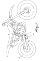
- a damping device can be fixed to a vehicle 2, which comprises a chassis 3 and at least one fork 4, which is suitable for rotatably accommodating a wheel 5.
- the vehicle 2 can be a road or off-road motorcycle (and the wheel 5 can be the rear one), particularly of the motocross type (as in the possible application of the device 1 shown in the accompanying figures), a supermotard or enduro motorcycle, be they intended for competitive use or for mere leisure.
- vehicles 2 designed to undergo intense forces on their suspensions and are therefore particularly subject to the problems that the device 1 according to the invention seeks to solve.
- the device 1 according to the invention can be used in all those fields of application in which travel over rough paths is expected, as occurs for example for mountain bikes.
- shock-absorbing element 6 of a known type, with viscoelastic behavior, is interposed between the chassis 3 and the fork 4, and in practice constitutes the core of the functional assembly designated by the generic term "suspension" of the vehicle 2.
- the shock-absorbing element 6 comprises an elastic element 7, which can be an axially actuated spring, which is compressed as a consequence of the passage of the wheel 5 over an irregularity of the ground, and whose elastic reaction allows to restore the normal travel configuration.
- a known type of cylinder 8, arranged for example internally and coaxially to the spring, ensures damping of the subsequent oscillations of the spring, whose energy is dissipated in order to overcome resistances of the viscous type that are present inside the cylinder 8.
- the damping device 1 comprises a block 9 made of a material that can be deformed in a substantially elastic manner and can be interposed between the chassis 3 and the fork 4, in order to intercept the stroke of the fork 4 with respect to the chassis 3 if such stroke is greater than a preset limit value that depends on the constructive characteristics of the vehicle 2.
- the elastic material of which the block 9 is made can be at least partly of the type of natural rubber.
- the block 9 is instead made of a material that is at least partly of the type of synthetic rubber.
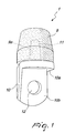
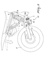
- the damping device 1 comprises a metal plate 10, which supports the block 9 and can engage either the chassis 3 or the fork 4 of the vehicle 2.
- the metal plate 10 is folded so as to form a first flat surface 10a, on which a body 11 is fixed, which in turn is coupled to a corresponding compartment 9a that is formed in the block 9, which for example has a substantially cylindrical shape.
- the metal plate 10 further has a second flat surface 10b, on which there is a seat 12 for coupling to the chassis 3 or to the fork 4 of the vehicle 2.
- the seat 12 can be coupled to an abutment, which is formed on either the chassis 3 or the fork 4, and faces and is proximate to a respective portion of the other between the chassis 3 and the fork 4, in order to intercept the stroke of the fork 4 with respect to the chassis 3 during the return of said fork.
- an abutment which is formed on either the chassis 3 or the fork 4, and faces and is proximate to a respective portion of the other between the chassis 3 and the fork 4, in order to intercept the stroke of the fork 4 with respect to the chassis 3 during the return of said fork.
- the block 9 in practice constitutes a new stroke limit for the fork 4, against which the latter stops, particularly during the expanding return stroke of the elastic element 7.
- the material of which the block 9 is made has such an elastic deformability value as to avoid, proximate to the end of the return stroke of the fork 4, a sudden stop of the parts of the vehicle 2 that are connected to the shock-absorbing element 6 and in particular to the chassis 3 that supports the driver, thus facilitating his comfort and, with reference to the application of the device 1 to motorcycles, avoiding the risk of such driver being thrown off the saddle.
- the metal plate 10, and in particular its seat 12, can engage an appropriate coupling element provided for this purpose on the vehicle 2, or more simply it is possible to utilize existing components of the vehicle 2 to which the plate 10 is coupled.
- the seat 12 formed on the second surface 10b can be fixed to an abutment formed on the chassis 3, so as to intercept a corresponding portion of the fork 4 during its return stroke.
- the metal plate 10, and particularly its seat 12 can engage transmission means 13, which actually provide the connection between the chassis 3, the fork 4 and the shock-absorbing element 6 and are typically present on most commercially available motocross bikes.
- the damping device according to the invention fully achieves the intended aim and objects, since the elastic deformability of the block fitted along the stroke of the fork with respect to the chassis allows to slow down and "soften” the final portion of the stroke of the fork, which stops against the new stroke limit represented by such block.
- the damping device according to the invention can be designed for use on motorcycles or other vehicles suitable for road or off-road use, such as for example mountain bikes, quad bikes, motorized sleds and motor vehicles in general.
- the materials used, as well as the dimensions, may be any according to requirements and to the state of the art.
Landscapes
- Engineering & Computer Science (AREA)
- Mechanical Engineering (AREA)
- Axle Suspensions And Sidecars For Cycles (AREA)
- Vibration Prevention Devices (AREA)
- Transition And Organic Metals Composition Catalysts For Addition Polymerization (AREA)
Applications Claiming Priority (1)
| Application Number | Priority Date | Filing Date | Title |
|---|---|---|---|
| IT000765A ITBO20070765A1 (it) | 2007-11-20 | 2007-11-20 | Dispositivo di smorzamento, specialmente per sospensioni di veicoli. |
Publications (2)
| Publication Number | Publication Date |
|---|---|
| EP2062755A2 true EP2062755A2 (fr) | 2009-05-27 |
| EP2062755A3 EP2062755A3 (fr) | 2010-09-22 |
Family
ID=40312160
Family Applications (1)
| Application Number | Title | Priority Date | Filing Date |
|---|---|---|---|
| EP08168018A Withdrawn EP2062755A3 (fr) | 2007-11-20 | 2008-10-31 | Dispositif amortisseur en particulier pour suspensions de véhicule |
Country Status (3)
| Country | Link |
|---|---|
| US (1) | US20090127757A1 (fr) |
| EP (1) | EP2062755A3 (fr) |
| IT (1) | ITBO20070765A1 (fr) |
Cited By (1)
| Publication number | Priority date | Publication date | Assignee | Title |
|---|---|---|---|---|
| IT202000007774A1 (it) * | 2020-04-14 | 2021-10-14 | Marco Andreani | Sospensione anti affondamento ad elemento elastico dedicato. |
Citations (1)
| Publication number | Priority date | Publication date | Assignee | Title |
|---|---|---|---|---|
| GB646017A (en) | 1947-01-02 | 1950-11-15 | George Spencer Moulton & Co | Improvements in and relating to spring suspensions for motor cycles and other vehicles |
Family Cites Families (13)
| Publication number | Priority date | Publication date | Assignee | Title |
|---|---|---|---|---|
| US1689883A (en) * | 1926-03-11 | 1928-10-30 | Mechanical Rubber Co | Vehicle suspension |
| US2678210A (en) * | 1950-03-20 | 1954-05-11 | Chrysler Corp | Bumper assembly |
| US2618494A (en) * | 1950-07-28 | 1952-11-18 | Moto Guzzi Soc P Az | Rear suspension of motor scooters |
| US2890895A (en) * | 1953-12-31 | 1959-06-16 | Gen Motors Corp | Rear spring suspension for vehicles |
| GB831657A (en) * | 1956-10-17 | 1960-03-30 | T G B Motors Ltd | Improvements in motor road vehicles |
| US2979353A (en) * | 1956-11-08 | 1961-04-11 | Clevite Harris Products Inc | Elastomer ball joint and method of assembling same |
| US3118659A (en) * | 1960-02-09 | 1964-01-21 | Luxembourg Brev Participations | Compression springs made of an elastomer |
| US3770077A (en) * | 1972-07-21 | 1973-11-06 | Gen Motors Corp | Vehicle suspension system |
| GB2037678A (en) * | 1978-12-18 | 1980-07-16 | Matthews R E | Motor cycles |
| US5149069A (en) * | 1991-11-08 | 1992-09-22 | Gencorp Inc. | Spring seat/jounce bumper assembly |
| US5238233A (en) * | 1992-09-15 | 1993-08-24 | Gencorp Inc. | Jounce bumper with hoop stress rings |
| US5467970A (en) * | 1994-06-06 | 1995-11-21 | General Motors Corporation | Vehicle suspension system with jounce bumper |
| JP3804885B2 (ja) * | 1997-07-31 | 2006-08-02 | 東洋ゴム工業株式会社 | バウンドストッパ及びその製造方法 |
-
2007
- 2007-11-20 IT IT000765A patent/ITBO20070765A1/it unknown
-
2008
- 2008-10-31 EP EP08168018A patent/EP2062755A3/fr not_active Withdrawn
- 2008-11-03 US US12/289,716 patent/US20090127757A1/en not_active Abandoned
Patent Citations (1)
| Publication number | Priority date | Publication date | Assignee | Title |
|---|---|---|---|---|
| GB646017A (en) | 1947-01-02 | 1950-11-15 | George Spencer Moulton & Co | Improvements in and relating to spring suspensions for motor cycles and other vehicles |
Cited By (1)
| Publication number | Priority date | Publication date | Assignee | Title |
|---|---|---|---|---|
| IT202000007774A1 (it) * | 2020-04-14 | 2021-10-14 | Marco Andreani | Sospensione anti affondamento ad elemento elastico dedicato. |
Also Published As
| Publication number | Publication date |
|---|---|
| US20090127757A1 (en) | 2009-05-21 |
| ITBO20070765A1 (it) | 2009-05-21 |
| EP2062755A3 (fr) | 2010-09-22 |
Similar Documents
| Publication | Publication Date | Title |
|---|---|---|
| CA2995818C (fr) | Un velo de neige et une suspension avant destinee a un velo a neige | |
| EP2956317B1 (fr) | Groupe de suspension, en particulier pour véhicules motorisés | |
| US5820114A (en) | Shock absorber | |
| USRE45503E1 (en) | Suspension structure | |
| US11745829B2 (en) | Snow bike track assembly | |
| JP2013527405A (ja) | プリロードされた2重スプリングアセンブリ | |
| US9573435B2 (en) | Dual inline hydraulic device | |
| US20120187653A1 (en) | Full suspension lock-out for a mountain bike that slides in, in place of the rear shock | |
| US7392874B2 (en) | Rear wheel suspension | |
| US20080036288A1 (en) | Wheel Shock Absorbing Apparatus | |
| EP2062755A2 (fr) | Dispositif amortisseur en particulier pour suspensions de véhicule | |
| US3687438A (en) | Motorcycle suspension apparatus | |
| KR100908002B1 (ko) | 자동차의 진동 흡수력 조절용 쇽업쇼버 | |
| JP3874385B2 (ja) | フロントフォーク | |
| CN114321254B (zh) | 一种适用于重载型全地形车的减震器 | |
| JPH0231036A (ja) | 車両用緩衝器 | |
| US20080169163A1 (en) | Harmonic dampener | |
| US2181692A (en) | Spring suspension for automobiles | |
| CA2863072C (fr) | Dispositif hydraulique aligne double | |
| KR101043129B1 (ko) | 차량용 독립식 현가장치 | |
| KR102418628B1 (ko) | 자동차의 후륜 현가장치 | |
| KR100559892B1 (ko) | 상용차용 현가장치의 범프스톱퍼 | |
| KR20040041292A (ko) | 허브와 림 사이에 완충장치를 가지는 휠 | |
| TW202525639A (zh) | 前兩輪車輛之懸吊裝置 | |
| JP3171800U (ja) | 自動2輪車における前輪支持装置 |
Legal Events
| Date | Code | Title | Description |
|---|---|---|---|
| PUAI | Public reference made under article 153(3) epc to a published international application that has entered the european phase |
Free format text: ORIGINAL CODE: 0009012 |
|
| AK | Designated contracting states |
Kind code of ref document: A2 Designated state(s): AT BE BG CH CY CZ DE DK EE ES FI FR GB GR HR HU IE IS IT LI LT LU LV MC MT NL NO PL PT RO SE SI SK TR |
|
| AX | Request for extension of the european patent |
Extension state: AL BA MK RS |
|
| PUAL | Search report despatched |
Free format text: ORIGINAL CODE: 0009013 |
|
| AK | Designated contracting states |
Kind code of ref document: A3 Designated state(s): AT BE BG CH CY CZ DE DK EE ES FI FR GB GR HR HU IE IS IT LI LT LU LV MC MT NL NO PL PT RO SE SI SK TR |
|
| AX | Request for extension of the european patent |
Extension state: AL BA MK RS |
|
| RIC1 | Information provided on ipc code assigned before grant |
Ipc: B60G 7/04 20060101ALI20100817BHEP Ipc: B62K 25/28 20060101ALI20100817BHEP Ipc: B60G 11/52 20060101AFI20090211BHEP |
|
| 17P | Request for examination filed |
Effective date: 20110322 |
|
| AKX | Designation fees paid |
Designated state(s): AT BE BG CH CY CZ DE DK EE ES FI FR GB GR HR HU IE IS IT LI LT LU LV MC MT NL NO PL PT RO SE SI SK TR |
|
| 17Q | First examination report despatched |
Effective date: 20111208 |
|
| STAA | Information on the status of an ep patent application or granted ep patent |
Free format text: STATUS: THE APPLICATION IS DEEMED TO BE WITHDRAWN |
|
| 18D | Application deemed to be withdrawn |
Effective date: 20120419 |