EP2062811A2 - Etrier de support doté de recouvrements correspondants pour bateaux à moteur - Google Patents
Etrier de support doté de recouvrements correspondants pour bateaux à moteur Download PDFInfo
- Publication number
- EP2062811A2 EP2062811A2 EP07388088A EP07388088A EP2062811A2 EP 2062811 A2 EP2062811 A2 EP 2062811A2 EP 07388088 A EP07388088 A EP 07388088A EP 07388088 A EP07388088 A EP 07388088A EP 2062811 A2 EP2062811 A2 EP 2062811A2
- Authority
- EP
- European Patent Office
- Prior art keywords
- flybridge
- bracket
- deck
- roof
- mainly
- Prior art date
- Legal status (The legal status is an assumption and is not a legal conclusion. Google has not performed a legal analysis and makes no representation as to the accuracy of the status listed.)
- Withdrawn
Links
- 238000003860 storage Methods 0.000 claims description 3
- 241000272165 Charadriidae Species 0.000 abstract 1
- 238000010276 construction Methods 0.000 description 13
- 229910000831 Steel Inorganic materials 0.000 description 4
- 239000004744 fabric Substances 0.000 description 4
- 229910001220 stainless steel Inorganic materials 0.000 description 4
- 239000010935 stainless steel Substances 0.000 description 4
- 239000010959 steel Substances 0.000 description 4
- 239000007787 solid Substances 0.000 description 3
- XLYOFNOQVPJJNP-UHFFFAOYSA-N water Substances O XLYOFNOQVPJJNP-UHFFFAOYSA-N 0.000 description 3
- 238000013461 design Methods 0.000 description 2
- 239000003365 glass fiber Substances 0.000 description 2
- 238000000034 method Methods 0.000 description 2
- 238000004904 shortening Methods 0.000 description 2
- 230000000475 sunscreen effect Effects 0.000 description 2
- 239000000516 sunscreening agent Substances 0.000 description 2
- 240000006829 Ficus sundaica Species 0.000 description 1
- 241000545744 Hirudinea Species 0.000 description 1
- 241001465382 Physalis alkekengi Species 0.000 description 1
- 241000630329 Scomberesox saurus saurus Species 0.000 description 1
- 238000010420 art technique Methods 0.000 description 1
- 238000007796 conventional method Methods 0.000 description 1
- 238000011161 development Methods 0.000 description 1
- 238000009826 distribution Methods 0.000 description 1
- OSUHJPCHFDQAIT-UHFFFAOYSA-N ethyl 2-{4-[(6-chloroquinoxalin-2-yl)oxy]phenoxy}propanoate Chemical compound C1=CC(OC(C)C(=O)OCC)=CC=C1OC1=CN=C(C=C(Cl)C=C2)C2=N1 OSUHJPCHFDQAIT-UHFFFAOYSA-N 0.000 description 1
- 239000011152 fibreglass Substances 0.000 description 1
- 238000009434 installation Methods 0.000 description 1
- 230000010354 integration Effects 0.000 description 1
- 238000010409 ironing Methods 0.000 description 1
- 239000000463 material Substances 0.000 description 1
- 230000003287 optical effect Effects 0.000 description 1
- 238000013021 overheating Methods 0.000 description 1
- 230000005855 radiation Effects 0.000 description 1
- 230000002787 reinforcement Effects 0.000 description 1
- 230000037072 sun protection Effects 0.000 description 1
- 238000012546 transfer Methods 0.000 description 1
- 238000003466 welding Methods 0.000 description 1
- 239000002023 wood Substances 0.000 description 1
Images


Classifications
-
- B—PERFORMING OPERATIONS; TRANSPORTING
- B63—SHIPS OR OTHER WATERBORNE VESSELS; RELATED EQUIPMENT
- B63B—SHIPS OR OTHER WATERBORNE VESSELS; EQUIPMENT FOR SHIPPING
- B63B17/00—Vessels parts, details, or accessories, not otherwise provided for
- B63B17/02—Awnings, including rigid weather protection structures, e.g. sunroofs; Tarpaulins; Accessories for awnings or tarpaulins
Definitions
- the invention relates to a support bracket for a motor boat with the function of a carrier of antennas, covers and other accessories containing at least two steel profiles, which are attached to a flybridge of a motor boat, up from each side of the motor boat and top by means of a top profile connected to each other.
- the invention has for its object to develop a support bracket with high strength in a visually weightless construction, which should be at the same time more stable moored to the boat, as is the case with conventional constructions.
- This object is achieved by combining a support bracket, which is known per se, with a guard rail guided along the flybridge of the motor boat so that the parts are integrated into one another and therefore support one another.
- Seereling means a number of mainly vertical columns, which are connected by a railing profile at the top, and the individual parts of stainless steel, possibly combined with wood, can be made.
- the sea rings, which are mounted fore and aft, act like discs which receive the longitudinal forces of the carrier bracket, with the foremost profiles of the carrier bracket added thereto contribute to support the fore and aft railing rails against a transverse ship running bend.
- the integration of the bracket in the Seereling not only creates a mutual reinforcement, but also a visually harmonious construction, since all parts are preferably made of the same materials, such. B. stainless steel pipes. This also strengthens the external impression of a weightless construction.
- the sides of the flybridge should be as wholly or partially composed of a fixed to the Seereling cover, which is the weightless, elegant outer expression, compared to the strong fiberglass constructions, as they are otherwise known from conventional, cumbersome looking motor boat models, to create leeches would not break.
- the support bracket should preferably coincide with the supports of the guard rail or even represent such, so that the tensile and compressive forces are transmitted directly to the boat.
- the Seereling can also have extra struts in both the fore and aft direction for optimum power transfer to the boat.
- the invention is particularly suited to solving a problem in covering motorboats against sun or rain.
- Shields of this type are z. B. by the U.S. Patents 5,520,139 . 5803104 and 2006/0124045 previously known, and the problems of the prior art will be explained below.
- the traditional motorboat type with a flybridge and a stay deck behind it usually has - or at least boats up to 40 feet - a relatively high flybridge so that when the flybridge deck rises aft to form the roof of the deck, it is reached at the latter headroom.
- These types of boats usually also have an obliquely upwards and aft projecting glass fiber strap on which antennas, headlights, lanterns, etc. can be attached, and the optically harmonized with the aft projecting roof over the residence deck.
- Such a construction is z.
- U.S. Patent 5,715,771 previously known.
- this boat type aft has a completely open, ie, roofless stay deck. On the one hand, this leads to a better outdoor feeling, on the other hand, the generation of sun or rain shadow is greatly impeded if this property has high priority for the user.
- the method of using sunshades and more permanent covers of the flybridge covers has also resulted in separate bow and bar systems on the newer motorboat type mentioned above, cf. the disadvantages with the conventional boat type, s. also U.S. Patent No. 5,520,139 ,
- a new construction of a bracket is instructed, which solves the problems described with respect to the newer motorboat type without a fixed roof over the resident deck, with the fast and effortless different effective shields can be built on the flybridge as well as the residence deck and the same time, both in the open as well as folded state of the shield, visually harmonizes with the weightless, open character of this boat type.
- the support bracket has a number of associated brackets that extend in a predefined outline each over two located on both sides of the boat bearings.
- This construction acts as a carrier of a tarpaulin, which in the extended state has a shape that is partially defined by said outline. This allows a stable sunshade to be built over the flybridge.
- a roof bar that extends over the residence deck. Due to the stability of the support bracket according to the invention, a permanent or foldable roof can be built over the living deck with the help of this roof bar.
- the storage points are mounted in the preferred embodiment at a height above the floorboard of the residence deck on the support bracket, which corresponds to the standing height on the residence deck.
- the roof bar can be mounted in a horizontal position by means of one or more fixed locking elements firmly mounted between the support bracket and roof bar and should, if desired, also be able to be opened against the back of the carrier bracket.
- the roof bar has a center bar that extends transversely between the longitudinal sides of the roof bar at a certain distance from the swinging bearings and the tail ends of the roof bar. This leads partly to an extra support of the Persenningstoffs, at the same time, however, has the advantage that the cover fabric can be stored in the folded state on the center pole, so that the folded cloth does not hinder the free passage between the resident deck and the flybridge with opened roof bar. If the tarpaulin cloth can be folded against the center bar, this does neither break the weightless and open character, nor prevents desired sunshine, so it is conceivable that many people prefer a solid connection between the support bracket and roof bar when boating.
- the roof bar can also be used as a grab handle as the center bar stabilizes it against lateral movement.
- the underside of the central rod can preferably be equipped with light fittings.
- the Persenningtuch located on the roof bar is provided at the edge with one or more zippers or the like, so that one or more side pieces can be zipped between the roof and the railing of the residence deck.
- the invention also represents a significant advance on this point.
- the stability achieved according to the invention by integrating the support bracket and the guard rail can be exploited in various ways.
- the flybridge cover is divided into two parts so that the front part is supported by the front part of the flybridge and the flybridge bracket, while the rear part is supported by the flybridge and the flybridge bracket.
- the two pieces can be joined together with a zipper along the flybridge bracket. So you can z. B. drive only with the front part of the boat, which more wind and rain shadow is generated and whereby it is possible that a hatch can be left open between the flybridge and the control room of the boat even in bad weather. This keeps the skipper in bad weather, the feeling of being in contact with the fresh air.
- the Flybridgebügel can also take a different position, in which the cross bar is preferably located at the height of the uppermost part of the support bracket or slightly lower, so that between the support bracket and the Flybridgebügel a sunshade cover can be stretched.
- the flybridge bracket is preferably attached using one or more bolts that are fixed to the flybridge bracket and flybridge.
- Fig. 1 shows an excerpt of a motor boat 1 of the type with a relatively low flybridge 2 and a residence deck 3 aft.
- the Flybridge and the resident deck each have a hallway 4, 5.
- the flybridge is so high that their hallway protrude beyond the living deck and so on the latter can form a roof with standing height, calculated from the height of the hallway 5.
- the invention is intended for a more modern type of motorboat, for which a weightless and open construction is sought over the low flybridge, which appeals to many people, especially former sailboat owners, who value functionality, proximity to water and fresh air, as well as numerous opportunities to be able to move on the boat.
- Conventional powerboats are often stuffy and have limited options for moving freely.
- a Seereling around the flybridge around with a support bracket in the under 6, Fig. 1 type indicated.
- a support bracket is often called Targabügel and usually consists of a number of curved and interconnected pipes, from z. B. stainless steel.
- the attachment of antennas and Persenningbügeln to a Targabügel is already known; so far, however, the practical load capabilities of such a temple were limited, and partly because of its stability and the other part of its attachment to the boat.
- the support bracket has in the illustrated embodiment, four steel profiles 9 - 12, preferably made of stainless steel tube, which in a manner known per se using a cover plate and a number of connecting rods in the fore and aft direction, z. B. 14 and 15, are interconnected.
- the support bracket is inventively integrated into the Seereling.
- the Seereling stanchions 16 - 23 which are above with the help of two fore and aft railing profiles 24, 25 and eighth by means of transverse ship railing profiles 26 and 27 connected to each other.
- Fig. 1 Two different ways are shown to integrate the front profiles 9 or 10 into the guard rail.
- the profile 9 extends to the floorboard 4, where it is fastened. Furthermore, it is welded or bolted to the railing rail 24.
- the profile 10 is fastened to the railing rail 25 and the railing support 22.
- the tensile and compressive forces in profile 9 become collected directly from the floorboard 4, while the forces are distributed in profile 10 on the stanchions and the railing rail.
- greater stability can be achieved by using relatively thin tension rods 28-30 each connected to the top and bottom of two adjacent stanchions.
- Fig. 2 For example, the details of one embodiment for securing the profiles 11 and 12 are shown, making it possible to fold down the support bracket during the passage of low-lying bridges.
- the profiles 9 and 10 would be split in two at a location between the respective rail 24 and 25 and the respective connecting bars 14 and 15.
- Fig. 2 It can be seen how the stanchion 18 is attached to the floor 4 and a steel plate 31, which in turn has been welded to the respective rail 24 and rails 27.
- the profile 11 is welded to an opposite steel plate 32, which is connected via a hinge 33 with the plate 31.
- the support bracket In the illustrated position, the support bracket would be rotated by about 45 degrees aft. The support bracket would be screwed in an upright position through the indicated holes 34, 35 and 36.
- the stanchion 18 is in Fig. 2 shown in the same thickness as profile 11. Due to the optimal distribution of forces that is achieved with the invention, it would not actually need this thickness; Nevertheless, it would be useful if you wanted to pull a bundle of antenna cable through the profile 11 and the stanchion 18.
- Fig. 2 further shows a bearing pin 37 for fixing the in Fig. 1
- a corresponding pin On the other side of the boat there is a corresponding pin, so that the roof bar, z. B. in the passage under a low bridge through, can be folded up and down. Otherwise, it is preferable to leave the roof bar on the whole permanently in a horizontal position, as in Fig. 1 is shown on which also two support rods 38, 39 are shown, which are permanently connected to the respective profiles 11 and 12 and a central rod 40. Any solid welding of the center rod 40 to the remainder of the roof bracket results in substantial resistance to side loads transmitted to the journal 37 at the strongest point of the bracket. The forces acting perpendicularly on the roof bar are absorbed by the support bars 38 and 39, from where they are transmitted directly to the profiles 11, 12 and forwarded via the connecting bars 14, 15.
- the residence deck 3 is usually wider than the support bracket 6, but it would be advantageous if the outlines of the roof bracket 7 would correspond to the shape of the stay deck. This would give more space and the tarpaulin would be easier to mold, so that between the side deck and the resident deck entrance openings could be formed. Therefore, it is preferable to design the roof bracket 7 wider than the bracket 6 and therefore it is also advisable to attach the support rods 38 and 39 at a certain distance from the sides of the roof bracket 7 on the central rod 40. This has no problems folding the tarpaulin 43 ( Fig. 3 ) result, since this is advantageously packed around the center rod 9 and attached to this, so that the cover can not flutter freely.
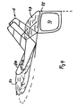
- FIG. 4 another cover 51 is shown with a disc 52.
- the stay deck can be completely shielded.
- This can be z. B. happen that the cover 43 along the entire edge zipper areas for teeth with zippers of the cover 15 has.
- their sides show a little inward, so that the roof bar 7 certainly corresponds to the contours of the living deck 3, but otherwise is a bit smaller.
- FIG. 1 also illustrates a Flybridgebügel 8 in its first position and the same bracket 8A in a different position. The function of this bracket is in connection with the Fig. 3 and 4 explained.
- FIG. 3 illustrates a sunshade 43 above the layover deck, as noted above, and a sunshade 44 above the flybridge.
- the sunshade over the flybridge is accomplished by supporting the tarpaulin 44 aft of the support bracket 6 and forward of the flybridge bracket 8. Furthermore, the cover is supported in the middle by means of an auxiliary bracket 45.
- the sunshade is stretched forward in a manner known per se by means of cords 46, 47, but aft the shield is held in place by the sturdy support bracket 6. This means that the cords 46, 47 can be stretched much more tightly than in the prior art technique, in which the shield is also stretched with a few strings.
- the sunshade invention is therefore much more stable than the previously known.
- the flybridge bracket is in the second position 8A, the auxiliary bracket 45A is located on the opposite side of the flybridge bracket for fixing to the flybridge bracket two dome points 48, 49 of the flybridge.
- the flybridge bow can be a carrier of a flybridge cover 50, s. Fig. 4 ,
- cover 50 is an example of a partial rain shield.
- the flybridge cover is divided into a front part and a rear part.
- the front flybridge cover 50 has a zipper along the flybridge bracket 8A so that a rear flybridge cover can easily be flipped along this flybridge bracket.
- the rear flybridge cover is not shown in the picture, but it can be deduced that the flybridge can be completely covered by stretching the cover aft and attaching to the rearmost part of the flybridge track.
- the rear portion of the flybridge cover may be zipped along the flybridge bracket 8 to the forward portion.
- the flybridge bracket 8 may be zipped along the flybridge bracket 8 to the forward portion.
Landscapes
- Chemical & Material Sciences (AREA)
- Engineering & Computer Science (AREA)
- Combustion & Propulsion (AREA)
- Mechanical Engineering (AREA)
- Ocean & Marine Engineering (AREA)
- Tents Or Canopies (AREA)
Applications Claiming Priority (1)
| Application Number | Priority Date | Filing Date | Title |
|---|---|---|---|
| DKPA200601601 | 2006-12-06 |
Publications (2)
| Publication Number | Publication Date |
|---|---|
| EP2062811A2 true EP2062811A2 (fr) | 2009-05-27 |
| EP2062811A3 EP2062811A3 (fr) | 2010-07-14 |
Family
ID=40545873
Family Applications (1)
| Application Number | Title | Priority Date | Filing Date |
|---|---|---|---|
| EP07388088A Withdrawn EP2062811A3 (fr) | 2006-12-06 | 2007-12-05 | Etrier de support doté de recouvrements correspondants pour bateaux à moteur |
Country Status (1)
| Country | Link |
|---|---|
| EP (1) | EP2062811A3 (fr) |
Citations (5)
| Publication number | Priority date | Publication date | Assignee | Title |
|---|---|---|---|---|
| US5520139A (en) | 1995-01-17 | 1996-05-28 | King; Paul F. | Boat canopy |
| US5715771A (en) | 1996-01-30 | 1998-02-10 | Global Yachts International, Inc. | Yacht with temporary enclosure |
| US5803104A (en) | 1996-12-28 | 1998-09-08 | Pollen; Randall Paul | Bimini cover for a deck of a water craft |
| US6691637B1 (en) | 2002-05-17 | 2004-02-17 | C. E. Smith Co., Inc. | Custom fit T-top for a marine vessel |
| US20060124045A1 (en) | 2002-09-12 | 2006-06-15 | Roger Tucker | Boat |
Family Cites Families (5)
| Publication number | Priority date | Publication date | Assignee | Title |
|---|---|---|---|---|
| DE19540473A1 (de) * | 1995-10-20 | 1997-04-24 | A W Niemeyer Wuppermann & Schm | Gestell zur stützenden Aufnahme von Abdeckplanen auf Sportbooten |
| DE19823377C1 (de) * | 1998-05-14 | 2000-01-20 | Haller Klaus Dieter | Multifunktionsdach für Yachten |
| US6799529B1 (en) * | 2002-12-23 | 2004-10-05 | Smar Top, Inc. | Tiltable boat top |
| US7331304B2 (en) * | 2004-10-25 | 2008-02-19 | Taylor Made Group, Inc. | Windshield system including tower frame |
| US7237749B2 (en) * | 2004-12-14 | 2007-07-03 | The Boeing Company | Collapsible mobile platform interior structure |
-
2007
- 2007-12-05 EP EP07388088A patent/EP2062811A3/fr not_active Withdrawn
Patent Citations (5)
| Publication number | Priority date | Publication date | Assignee | Title |
|---|---|---|---|---|
| US5520139A (en) | 1995-01-17 | 1996-05-28 | King; Paul F. | Boat canopy |
| US5715771A (en) | 1996-01-30 | 1998-02-10 | Global Yachts International, Inc. | Yacht with temporary enclosure |
| US5803104A (en) | 1996-12-28 | 1998-09-08 | Pollen; Randall Paul | Bimini cover for a deck of a water craft |
| US6691637B1 (en) | 2002-05-17 | 2004-02-17 | C. E. Smith Co., Inc. | Custom fit T-top for a marine vessel |
| US20060124045A1 (en) | 2002-09-12 | 2006-06-15 | Roger Tucker | Boat |
Also Published As
| Publication number | Publication date |
|---|---|
| EP2062811A3 (fr) | 2010-07-14 |
Similar Documents
| Publication | Publication Date | Title |
|---|---|---|
| EP0987168A2 (fr) | Cloison pour une carrosserie monocoque | |
| DE102016014739A1 (de) | amphibischer Wohnwagen | |
| DE2649577A1 (de) | Wasserfahrzeug | |
| DE2348796A1 (de) | Sonnenschutzdach | |
| DE1456318A1 (de) | Zusammenlegbares,seetuechtiges Kajuetenboot | |
| DE1290832B (de) | Campinganhaenger | |
| DE4033883C1 (en) | Boat made of separate sections - has rubber cushions between sections which can be taken apart and nested together | |
| DE1808211A1 (de) | Aufbau fuer die Segel- und Steuereinrichtungen an Kleinbooten | |
| CH651793A5 (en) | Inflatable boat | |
| DE2541401A1 (de) | Wasserfahrzeug | |
| DE10151178C2 (de) | Starres, zerlegbares Boot und Katamaran | |
| DE102013003460A1 (de) | Zusatzdachvorrichtung zur Anordnung an einer Kraftfahrzeugkarosserie | |
| DE1781167C3 (de) | Höhenverstellbare Kajüte für Motor- oder Segelboote mit einem heb- und senkbaren Kajütdach | |
| CH533032A (de) | Ein- oder mehrrumpfiges Wasserfahrzeug, insbesondere Motor- oder Segelboot, mit geschlossenem, eine Tür aufweisendem Aufbau in Form einer Kajüte | |
| EP3456621B1 (fr) | Embarcation pliable | |
| DE69306688T2 (de) | Boot mit aufblasbaren Elementen, die einen starren Boden unterstützen und das mit einem Heckraum versehen ist, der begehbar ist durch zwei Türen, die teilweise in Heckrichtung gedreht werden können | |
| AT406757B (de) | Windenergieantriebselement | |
| DE3323768A1 (de) | Zusammenfaltbarer, vorzugsweise pontonfoermiger bootskoerper | |
| DE102024002654A1 (de) | Camping-Domizil | |
| DE102023002624A1 (de) | Kraftfahrzeug | |
| DE3805135C2 (fr) | ||
| DE2104838A1 (de) | Cockpitzelt | |
| DE7529350U (de) | Insbesondere zusammensetzbares oder zusammenlegbares Boot | |
| DE7524118U (de) | Sonnensegelanordnung fuer boote | |
| DE202018107143U1 (de) | Softtop-Dach aus zwei Stoffen |
Legal Events
| Date | Code | Title | Description |
|---|---|---|---|
| PUAI | Public reference made under article 153(3) epc to a published international application that has entered the european phase |
Free format text: ORIGINAL CODE: 0009012 |
|
| AK | Designated contracting states |
Kind code of ref document: A2 Designated state(s): AT BE BG CH CY CZ DE DK EE ES FI FR GB GR HU IE IS IT LI LT LU LV MC MT NL PL PT RO SE SI SK TR |
|
| AX | Request for extension of the european patent |
Extension state: AL BA HR MK RS |
|
| PUAL | Search report despatched |
Free format text: ORIGINAL CODE: 0009013 |
|
| AK | Designated contracting states |
Kind code of ref document: A3 Designated state(s): AT BE BG CH CY CZ DE DK EE ES FI FR GB GR HU IE IS IT LI LT LU LV MC MT NL PL PT RO SE SI SK TR |
|
| AX | Request for extension of the european patent |
Extension state: AL BA HR MK RS |
|
| AKY | No designation fees paid | ||
| REG | Reference to a national code |
Ref country code: DE Ref legal event code: R108 Effective date: 20110222 Ref country code: DE Ref legal event code: 8566 |
|
| STAA | Information on the status of an ep patent application or granted ep patent |
Free format text: STATUS: THE APPLICATION IS DEEMED TO BE WITHDRAWN |
|
| 18D | Application deemed to be withdrawn |
Effective date: 20110115 |