EP2062814B1 - Verfahren und werkzeug zur herstellung von röhrenförmigen komponenten für röhrenförmige rümpfe - Google Patents
Verfahren und werkzeug zur herstellung von röhrenförmigen komponenten für röhrenförmige rümpfe Download PDFInfo
- Publication number
- EP2062814B1 EP2062814B1 EP06807951.6A EP06807951A EP2062814B1 EP 2062814 B1 EP2062814 B1 EP 2062814B1 EP 06807951 A EP06807951 A EP 06807951A EP 2062814 B1 EP2062814 B1 EP 2062814B1
- Authority
- EP
- European Patent Office
- Prior art keywords
- jig
- tubular
- panels
- stiffeners
- stringers
- Prior art date
- Legal status (The legal status is an assumption and is not a legal conclusion. Google has not performed a legal analysis and makes no representation as to the accuracy of the status listed.)
- Not-in-force
Links
Images


Classifications
-
- B—PERFORMING OPERATIONS; TRANSPORTING
- B29—WORKING OF PLASTICS; WORKING OF SUBSTANCES IN A PLASTIC STATE IN GENERAL
- B29C—SHAPING OR JOINING OF PLASTICS; SHAPING OF MATERIAL IN A PLASTIC STATE, NOT OTHERWISE PROVIDED FOR; AFTER-TREATMENT OF THE SHAPED PRODUCTS, e.g. REPAIRING
- B29C70/00—Shaping composites, i.e. plastics material comprising reinforcements, fillers or preformed parts, e.g. inserts
- B29C70/04—Shaping composites, i.e. plastics material comprising reinforcements, fillers or preformed parts, e.g. inserts comprising reinforcements only, e.g. self-reinforcing plastics
- B29C70/28—Shaping operations therefor
- B29C70/30—Shaping by lay-up, i.e. applying fibres, tape or broadsheet on a mould, former or core; Shaping by spray-up, i.e. spraying of fibres on a mould, former or core
- B29C70/34—Shaping by lay-up, i.e. applying fibres, tape or broadsheet on a mould, former or core; Shaping by spray-up, i.e. spraying of fibres on a mould, former or core and shaping or impregnating by compression, i.e. combined with compressing after the lay-up operation
-
- B—PERFORMING OPERATIONS; TRANSPORTING
- B29—WORKING OF PLASTICS; WORKING OF SUBSTANCES IN A PLASTIC STATE IN GENERAL
- B29C—SHAPING OR JOINING OF PLASTICS; SHAPING OF MATERIAL IN A PLASTIC STATE, NOT OTHERWISE PROVIDED FOR; AFTER-TREATMENT OF THE SHAPED PRODUCTS, e.g. REPAIRING
- B29C33/00—Moulds or cores; Details thereof or accessories therefor
- B29C33/30—Mounting, exchanging or centering
- B29C33/307—Mould plates mounted on frames; Mounting the mould plates; Frame constructions therefor
-
- B—PERFORMING OPERATIONS; TRANSPORTING
- B29—WORKING OF PLASTICS; WORKING OF SUBSTANCES IN A PLASTIC STATE IN GENERAL
- B29C—SHAPING OR JOINING OF PLASTICS; SHAPING OF MATERIAL IN A PLASTIC STATE, NOT OTHERWISE PROVIDED FOR; AFTER-TREATMENT OF THE SHAPED PRODUCTS, e.g. REPAIRING
- B29C33/00—Moulds or cores; Details thereof or accessories therefor
- B29C33/44—Moulds or cores; Details thereof or accessories therefor with means for, or specially constructed to facilitate, the removal of articles, e.g. of undercut articles
- B29C33/48—Moulds or cores; Details thereof or accessories therefor with means for, or specially constructed to facilitate, the removal of articles, e.g. of undercut articles with means for collapsing or disassembling
- B29C33/485—Moulds or cores; Details thereof or accessories therefor with means for, or specially constructed to facilitate, the removal of articles, e.g. of undercut articles with means for collapsing or disassembling cores or mandrels
-
- B—PERFORMING OPERATIONS; TRANSPORTING
- B29—WORKING OF PLASTICS; WORKING OF SUBSTANCES IN A PLASTIC STATE IN GENERAL
- B29D—PRODUCING PARTICULAR ARTICLES FROM PLASTICS OR FROM SUBSTANCES IN A PLASTIC STATE
- B29D99/00—Subject matter not provided for in other groups of this subclass
- B29D99/001—Producing wall or panel-like structures, e.g. for hulls, fuselages, or buildings
- B29D99/0014—Producing wall or panel-like structures, e.g. for hulls, fuselages, or buildings provided with ridges or ribs, e.g. joined ribs
-
- B—PERFORMING OPERATIONS; TRANSPORTING
- B64—AIRCRAFT; AVIATION; COSMONAUTICS
- B64C—AEROPLANES; HELICOPTERS
- B64C1/00—Fuselages; Constructional features common to fuselages, wings, stabilising surfaces or the like
- B64C1/06—Frames; Stringers; Longerons ; Fuselage sections
- B64C1/068—Fuselage sections
-
- B—PERFORMING OPERATIONS; TRANSPORTING
- B64—AIRCRAFT; AVIATION; COSMONAUTICS
- B64U—UNMANNED AERIAL VEHICLES [UAV]; EQUIPMENT THEREFOR
- B64U20/00—Constructional aspects of UAVs
- B64U20/60—UAVs characterised by the material
- B64U20/65—Composite materials
-
- B—PERFORMING OPERATIONS; TRANSPORTING
- B29—WORKING OF PLASTICS; WORKING OF SUBSTANCES IN A PLASTIC STATE IN GENERAL
- B29L—INDEXING SCHEME ASSOCIATED WITH SUBCLASS B29C, RELATING TO PARTICULAR ARTICLES
- B29L2031/00—Other particular articles
- B29L2031/30—Vehicles, e.g. ships or aircraft, or body parts thereof
- B29L2031/3076—Aircrafts
- B29L2031/3082—Fuselages
-
- Y—GENERAL TAGGING OF NEW TECHNOLOGICAL DEVELOPMENTS; GENERAL TAGGING OF CROSS-SECTIONAL TECHNOLOGIES SPANNING OVER SEVERAL SECTIONS OF THE IPC; TECHNICAL SUBJECTS COVERED BY FORMER USPC CROSS-REFERENCE ART COLLECTIONS [XRACs] AND DIGESTS
- Y02—TECHNOLOGIES OR APPLICATIONS FOR MITIGATION OR ADAPTATION AGAINST CLIMATE CHANGE
- Y02T—CLIMATE CHANGE MITIGATION TECHNOLOGIES RELATED TO TRANSPORTATION
- Y02T50/00—Aeronautics or air transport
- Y02T50/40—Weight reduction
-
- Y—GENERAL TAGGING OF NEW TECHNOLOGICAL DEVELOPMENTS; GENERAL TAGGING OF CROSS-SECTIONAL TECHNOLOGIES SPANNING OVER SEVERAL SECTIONS OF THE IPC; TECHNICAL SUBJECTS COVERED BY FORMER USPC CROSS-REFERENCE ART COLLECTIONS [XRACs] AND DIGESTS
- Y10—TECHNICAL SUBJECTS COVERED BY FORMER USPC
- Y10T—TECHNICAL SUBJECTS COVERED BY FORMER US CLASSIFICATION
- Y10T29/00—Metal working
- Y10T29/49—Method of mechanical manufacture
- Y10T29/49616—Structural member making
- Y10T29/49622—Vehicular structural member making
Definitions
- the present invention relates to a process and a fig for manufacturing cylindrical or cylindrical-conical type tubular components of aeronautical fuselages made of composite materials formed by an outer skin without joints, longitudinal stiffeners or stringers and transverse ribs.
- weight is an essential aspect due to which optimized structures manufactured with composite materials are given priority over metallic structures.
- An object of the present invention is to provide a tubular component for aeronautical fuselages facilitating the subsequent incorporation of transverse ribs, therefore simplifying the fuselage manufacture.
- Another object of the present invention is to provide an efficient process for manufacturing the aforementioned component.
- Another object of the present invention is to provide a jig for carrying out the aforementioned process that does not require being removed in each production cycle so as to be able to withdraw the tubular component.
- a tubular-shaped component for an aeronautical fuselage made of composite materials comprising an outer skin without joints with a cylindrical or cylindrical-conical shape, a plurality of stiffeners or stringers longitudinally arranged in said outer skin and a plurality of anchoring elements for anchoring other elements to be subsequently incorporated, transversely arranged between said stiffeners or stringers.
- This component is manufactured by means of a process as disclosed in claim 1.
- the invention in turn provides a jig for implementing said process comprising a support body and a plurality of panels that can shift between an extended position and a retracted position in both directions, being configured as disclosed in claim 3.
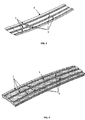
- An embodiment of the invention shall be described below in relation to a cylindrical or cylindrical-conical-type tubular-shaped component 19 made of a composite material formed by a skin 1, a plurality of omega-shaped stiffeners 2 arranged longitudinally and a plurality of anchoring elements 3 with I-shaped profiles arranged transversally.
- stiffener or stringer comprises any element integrated with the skin 1 having a stiffening function and arranged in the direction indicated by the arrow 4 of Figure 2 , i.e. in a direction parallel to the axis of the tubular component 19.
- anchoring element 3 comprises any element integrated with the skin with a function of supporting a structural element such as a rib to be subsequently incorporated and usually arranged in a direction parallel to the direction indicated by the arrow 5 of Figure 2 , although any person skilled in the art will understand that they would not necessarily have to be arranged in a direction that is strictly perpendicular to that of the stiffeners or stringers, but certain deviations would be allowable.
- composite material is understood to be any material consisting of fibers or fiber bundles embedded in a thermosetting or thermoplastic resin matrix and particularly those based on epoxy resins and carbon fibers.
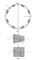
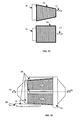
- the jig 18 basically consists of a support body 12 on which several mobile panels 9 are located which, in the extended position 10 externally have the inner geometry of the tubular component 19 to be manufactured.
- the panels 9 can be freely retracted in the direction indicated by arrow 11 to a position 10' where there are no obstacles for extracting the tubular component 19 once it is cured in the direction of arrow 17.
- the manufacturing process is based on locating the stiffeners or stringers 2 in the slots 7 and the anchoring elements 3 in the slots 8 of the jig 18. If the stiffeners or stringers 2 are omega-shaped as shown in the Figures or another closed shape and the taping of the skin 1 is done with a machine having a pressure head 13, auxiliary male elements 14 are arranged inside the stiffeners 2 so that the resulting geometry is the surface on which the composite material forming the skin 1 is to be taped. In this step of the process, the jig 18 maintains the panels 9 in the extended position 10.
- a membrane 20 is externally placed and sealed against the support body 12 of the jig 18.
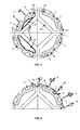
- the jig 18 comprises four panels 9 having a sectional shape which, in the extended position, occupy most of the outer surface of the jig 18 and a support body 12 with four areas whose external parts 31 occupy the rest of the outer surface of the jig 18.
- the support body 12 of the jig 18 comprises removable sections 25 between every two panels 9.
- the moving panels 9 in the extended position 10 together with all the removable sections 25 externally have the inner geometry of the tubular component 19 to be manufactured.
- the panels 9 can be freely retracted in the direction indicated by arrow 11 to a position 10' where there are no obstacles for the extraction of the cured tubular component 19 in the direction of arrow 17 and, in contrast, the removable sections 25 can be shifted with respect to the support body 12 in the direction indicated by arrow 26 to a position where they are not an obstacle for extracting the tubular component 19.
- the slots 8 of the anchoring elements can only be located in the panels 9.
- the retraction movement for retracting the panels 9 in the direction indicated by arrow 11 can be guided by elements fixed in the support body 12 to assure a correct taping position and collision-free movement.
- the retraction direction 11 to retract the panels 9 conditions the design of the slots 7 and 8 and at the same time the design of the stiffeners 2 and anchoring elements 3.
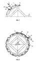
- the shape of the stiffener or stringer 23 represented in this figure would interfere with the retraction movement for retracting the panels 9 in the direction indicated by arrow 11 and would prevent the extraction of the tubular component 19.
- the allowable shapes of the stiffeners or stringers 2 would be those which, considering a radial retraction direction 24 corresponding to in one embodiment of the present invention the halving of the section occupied by each panel 9 and perpendicular to the axis of rotation 15 of the jig 18, have a surface that will be completely illuminated by a hypothetical focus located in infinity according to the direction 24 which projects light towards the stiffener or stringer 2 against the panel 1.
- the retraction direction 11 to retract the panels 9 is conditioned by their number and the angular section covered by each one.
- the support body 12 of the jig 18 is the element that secures the panels 9 in the correct position during the curing process.
- the sealing of the interfaces 29 between the panels 9 and the support body 12 or the removable sections 25, or between the these and the support body 12 is not critical for the curing process for curing the composite material and only requires to avoid the flow of the liquid resin to the inside of the openings 27 of the support body 12 so as not to block the mobility of the parts during the process.
- the support body 12 has to be airtight in conditions for curing composite materials, and therefore the curing membrane 20 is sealed against the support 12 in areas 28 keeping all the other mobile elements in contact with the composite material confined. Given that the support body 12 is not an element with mobile parts, sealings do not need to be replaced with each manufacturing cycle.
- the shifting of the panels 9 between the extended position 10, in which the taping and curing operations for taping and curing the tubular component 19 are carried out, and the retracted position 10', in which the tubular component is extracted it can be carried out pneumatically for example by connecting pneumatic cushions 21 to inner conduits 22 to the support body 12 through permanent seals.
- the taping is done with a fiber placement machine and by rotating the jig 18 about its axis in the direction indicated by arrow 15.
- stiffeners or stringers 2 and rib anchors 3 must remain well secured and positioned while the rotations occur and before they are joined to the skin 1 by means of, for example, several strips around the jig 18. If the stiffeners or stringers 2 have closed shapes, as previously mentioned, they would require the use of auxiliary male elements 14, which would also have to be secured by said bands.
Landscapes
- Engineering & Computer Science (AREA)
- Mechanical Engineering (AREA)
- Chemical & Material Sciences (AREA)
- Composite Materials (AREA)
- Remote Sensing (AREA)
- Aviation & Aerospace Engineering (AREA)
- Materials Engineering (AREA)
- Architecture (AREA)
- Civil Engineering (AREA)
- Structural Engineering (AREA)
- Moulding By Coating Moulds (AREA)
Claims (8)
- Verfahren zur Herstellung eines rohrförmigen Bauteils (19) für Flugzeugrümpfe aus Verbundmaterialien, mit einer fugenlosen Außenhaut (1) von zylindrischer oder zylindrisch-konischer Form, mehreren Versteifungselementen oder Stringern (2), die in der Außenhaut (1) in Längsrichtung angeordnet sind, und mehreren, in Querrichtung zwischen den Versteifungselementen und den Stringern (2) angeordneten Verankerungselementen (3) zum Verankern anderer Elemente, die anschließend in das rohrförmige Bauteil (19) eingebaut werden, wobei das Verfahren die folgenden Schritte aufweist:a) Vorsehen eines Montagegestells (18) mit einer Außenfläche, deren Form der Innenfläche des rohrförmigen Bauteils (19) ähnlich ist, mit Schlitzen (7, 8) zum Aufnehmen der Versteifungselemente oder Stringer (2) beziehungsweise der Verankerungselemente (3);b) Vorsehen der Versteifungselemente oder Stringer (2) und der Verankerungselemente (3) und Anordnen derselben in den Schlitzen (7, 8);c) Laminieren der Außenhaut (1) auf das Montagegestell (18);d) Anwenden eines Autoklav-Härtungszyklus auf die Anordnung aus dem Montagegestell (18) und dem rohrförmigen Bauteil (19), das mit einer Aushärtmembran (20) versehen ist;e) Herausziehen des rohrförmigen Bauteils (19) mittels einer längsgerichteten Bewegung nach dem Verschieben derjenigen Elemente des Montagegestells (18), die dies verhindern;
wobei das Verschieben von Teilen der Elemente des Montagegestells (18) im Schritt e) durchgeführt wird, indem diese in Radialrichtung (11) zurückgezogen werden, ohne sie von dem Montagegestell zu entfernen, und das Verschieben eines anderen Teils der Elemente des Montagegestells (18) in Längsrichtung (17) erfolgt, nachdem diese von dem Montagegestell (18) entfernt wurden. - Verfahren zur Herstellung eines rohrförmigen Bauteils (19) für Flugzeugrümpfe aus Verbundmaterialien nach Anspruch 1, bei welchem der Schritt c) mit einer Faserlegemaschine durchgeführt wird, indem das Montagegestell (18) gedreht wird und Einrichtungen zum Halten der Versteifungselemente oder Stringer (2) und der Verankerungselemente (3) in ihren Positionen verwendet werden.
- Montagegestell (18) zur Herstellung von rohrförmigen Bauteilen (19) für Flugzeugrümpfe aus Verbundmaterialien, mit einer fugenlosen Außenhaut (1) von zylindrischer oder zylindrisch-konischer Form, mehreren Versteifungselementen oder Stringern (2), die in der Außenhaut (1) in Längsrichtung angeordnet sind, und mehreren, in Querrichtung zwischen den Versteifungselementen und den Stringern (2) angeordneten Verankerungselementen (3) zum Verankern anderer Elemente, die anschließend in das rohrförmige Bauteil (19) eingebaut werden, mit einem Stützkörper (12) und mehreren Platten (9) in Form von Rohrabschnitten, welche zwischen einer ausgefahrenen Position (10) und einer zurückgezogenen Position (10') in beide Richtungen verschiebbar sind, wobei das Montagegestell derart ausgebildet ist, dass:a) die Form der Außenfläche des Montagegestells (18) mit in der ausgefahrenen Position (10) befindlichen Platten (9) der Form der Innenfläche der rohrförmigen Bauteile (19) ähnlich ist, mit Schlitzen (7, 8) zum Aufnehmen der Versteifungselemente oder Stringer (2) beziehungsweise der Verankerungselemente (3);b) die Platten (9) zwischen der ausgefahrenen Position (10) und der zurückgezogenen Position (10') in Radialrichtung (11) verschiebbar sind, ohne irgendein Element des rohrförmigen Bauteils (19) zu beeinträchtigen;
dadurch gekennzeichnet, dass der Stützkörper (12) entfernbare Platten (25) in dem Teil der Oberfläche des Montagegestells (18) aufweist, der von den Platten (9) in der ausgefahrenen Position (10) nicht abgedeckt wird. - Montagegestell (18) zur Herstellung von rohrförmigen Bauteilen (19) für Flugzeugrümpfe aus Verbundmaterialien nach Anspruch 3, bei welchem die in der Außenfläche des Montagegestells (18) zwischen den in der ausgefahrenen Position (10) befindlichen Platten (9) und dem Stützkörper (12) existierenden Fugen derart ausgebildet sind, dass sie abdichtbar sind, um das flüssige Harz des Verbundmaterials während des Aushärtens des rohrförmigen Bauteils (19) zurückzuhalten.
- Montagegestell (18) zur Herstellung von rohrförmigen Bauteilen (19) für Flugzeugrümpfe aus Verbundmaterialien nach einem der Ansprüche 3-4, bei welchem die Schlitze (8) zur Aufnahme der Verankerungselemente (3) in den Platten (9) angeordnet sind.
- Montagegestell (18) zur Herstellung von rohrförmigen Bauteilen (19) für Flugzeugrümpfe aus Verbundmaterialien nach einem der Ansprüche 3-5, bei welchem die in den Platten (9) zum Aufnehmen der Versteifungselemente oder Stringer (2) vorgesehenen Schlitze (7) mit einer beliebigen Form ausgebildet sind, die es ermöglicht, die Versteifungselemente oder Stringer (2) mit einer hypothetischen Lampe vollständig zu beleuchten, welche in Richtung (24) der Halbierenden der von den Platten (9) eingenommenen Abschnitte in der Unendlichkeit angeordnet ist.
- Montagegestell (18) zur Herstellung von rohrförmigen Bauteilen (19) für Flugzeugrümpfe aus Verbundmaterialien nach einem der Ansprüche 3-6, ferne mit pneumatischen Kissen (21) zum Verschieben der Platten (9) zwischen der ausgefahrenen Position (10) und der zurückgezogenen Position (10').
- Montagegestell (18) zur Herstellung von rohrförmigen Bauteilen (19) für Flugzeugrümpfe aus Verbundmaterialien nach einem der Ansprüche 3-7, welches vier Platten (9) aufweist.
Applications Claiming Priority (1)
| Application Number | Priority Date | Filing Date | Title |
|---|---|---|---|
| PCT/ES2006/070131 WO2008025860A1 (es) | 2006-08-31 | 2006-08-31 | Componentes tubulares para fuselajes aeronauticos y procedimientos y utiles para su fabricacion |
Publications (3)
| Publication Number | Publication Date |
|---|---|
| EP2062814A1 EP2062814A1 (de) | 2009-05-27 |
| EP2062814A4 EP2062814A4 (de) | 2012-01-25 |
| EP2062814B1 true EP2062814B1 (de) | 2013-07-10 |
Family
ID=39135519
Family Applications (1)
| Application Number | Title | Priority Date | Filing Date |
|---|---|---|---|
| EP06807951.6A Not-in-force EP2062814B1 (de) | 2006-08-31 | 2006-08-31 | Verfahren und werkzeug zur herstellung von röhrenförmigen komponenten für röhrenförmige rümpfe |
Country Status (4)
| Country | Link |
|---|---|
| US (1) | US7597772B2 (de) |
| EP (1) | EP2062814B1 (de) |
| ES (1) | ES2430554T3 (de) |
| WO (1) | WO2008025860A1 (de) |
Families Citing this family (34)
| Publication number | Priority date | Publication date | Assignee | Title |
|---|---|---|---|---|
| WO2007113345A1 (es) * | 2006-03-31 | 2007-10-11 | Airbus España, S.L. | Procedimiento de fabricacion de estructuras de material compuesto con un utillaje colapsable |
| DE102006026168A1 (de) | 2006-06-06 | 2008-01-31 | Airbus Deutschland Gmbh | Flugzeugrumpfstruktur und Verfahren zu deren Herstellung |
| DE102006026169B4 (de) * | 2006-06-06 | 2012-06-21 | Airbus Operations Gmbh | Flugzeugrumpfstruktur und Verfahren zu deren Herstellung |
| DE102006026170B4 (de) * | 2006-06-06 | 2012-06-21 | Airbus Operations Gmbh | Flugzeugrumpfstruktur und Verfahren zu deren Herstellung |
| ES2352941B1 (es) | 2008-05-16 | 2012-01-25 | Airbus Operations, S.L. | Estructura integrada de aeronave en material compuesto |
| DE102009056978A1 (de) | 2009-12-07 | 2011-06-09 | Airbus Operations Gmbh | Vorrichtung und Verfahren zur Herstellung einer aus einem Faserverbundwerkstoff bestehenden Rumpfschale für ein Luftfahrzeug |
| FR2953754B1 (fr) * | 2009-12-16 | 2018-03-02 | Airbus Operations | Outillage pour la fabrication d'un panneau en materiau composite, en particulier d'un fuselage d'aeronef |
| JP5576651B2 (ja) * | 2009-12-25 | 2014-08-20 | 川崎重工業株式会社 | 複合材料構造物製造用マンドレルの組立方法およびマンドレルの組立装置 |
| JP5576652B2 (ja) * | 2009-12-25 | 2014-08-20 | 川崎重工業株式会社 | 複合材料構造物製造用マンドレルの分解方法およびマンドレルの分解装置 |
| DE102010008711A1 (de) * | 2010-02-19 | 2011-08-25 | GKN Aerospace Services Limited, Isle of Wight | Verfahren und Anordnung zur Herstellung eines einstückigen Hohlprofilbauteils mit Faserverbundwerkstoff |
| DE102011010539A1 (de) | 2011-02-07 | 2012-08-09 | Airbus Operations Gmbh | Aufrüstvorrichtung und Verfahren zur Herstellung einer aus einem Faserverbundwerkstoff bestehenden Rumpftonne für ein Luftfahrzeug |
| US10464656B2 (en) * | 2011-11-03 | 2019-11-05 | The Boeing Company | Tubular composite strut having internal stiffening and method for making the same |
| US8714226B2 (en) * | 2012-02-27 | 2014-05-06 | The Boeing Company | Automated fiber placement including layup mandrel tool |
| ITTO20120287A1 (it) * | 2012-03-30 | 2013-10-01 | Alenia Aermacchi Spa | Sistema posizionamento settori appartenenti ad un dispositivo per la realizzazione di una sezione di fusoliera di un aereo |
| ITTO20120286A1 (it) * | 2012-03-30 | 2013-10-01 | Alenia Aermacchi Spa | Sistema di vincolo settori appartenenti ad un dispositivo per la realizzazione di una sezione di fusoliera di un aereo |
| US9199417B1 (en) * | 2013-01-02 | 2015-12-01 | The Boeing Company | Systems and methods for assembling stiffened composite structures |
| US9221235B1 (en) * | 2013-01-02 | 2015-12-29 | The Boeing Company | Systems and methods for assembling stiffened composite structures |
| US9221236B1 (en) * | 2013-01-02 | 2015-12-29 | The Boeing Company | Systems and methods for assembling stiffened composite structures |
| JP6281865B2 (ja) * | 2014-01-31 | 2018-02-21 | 三菱重工業株式会社 | Frp成形治具及びfrp構造体の成形方法 |
| US9597843B2 (en) | 2014-05-15 | 2017-03-21 | The Boeing Company | Method and apparatus for layup tooling |
| US9545778B2 (en) * | 2014-08-04 | 2017-01-17 | The Boeing Company | System and method for applying pressure to structural components |
| US9873500B2 (en) | 2014-09-16 | 2018-01-23 | The Boeing Company | Process and apparatus for handling, installing, compacting, splicing, and/or assembling composite stringers |
| US10434687B2 (en) | 2014-12-17 | 2019-10-08 | Sikorsky Aircraft Corporation | Composite laminate tooling and method of forming a composite part using the tooling |
| US9669589B2 (en) * | 2015-06-08 | 2017-06-06 | Siemens Aktiengesellschaft | Hybrid solid-inflatable mandrel for blade manufacturing |
| EP3272640B1 (de) | 2016-07-21 | 2019-04-17 | AIRBUS HELICOPTERS DEUTSCHLAND GmbH | Hubschrauber mit einem rumpf und einem verbundstoffheckausleger |
| EP3281861B1 (de) * | 2016-08-11 | 2019-10-02 | AIRBUS HELICOPTERS DEUTSCHLAND GmbH | Drehflügler mit einem rumpf mit mindestens einem strukturell versteiften paneel |
| US11331867B2 (en) * | 2016-08-23 | 2022-05-17 | Textron Innovations, Inc. | Nested manufacturing of composite structures |
| CN106882356B (zh) * | 2017-01-22 | 2023-11-03 | 江苏诚益达智能科技有限公司 | 带电池箱的多旋翼遥控飞行无人机机壳 |
| DE102018207763A1 (de) * | 2018-05-17 | 2019-11-21 | Airbus Operations Gmbh | Rumpfstruktur für ein Luftfahrzeug |
| NL2027417B1 (en) * | 2021-01-26 | 2022-08-26 | Boeing Co | Fabrication line, systems, and methods for fuselage sections |
| EP4000845B1 (de) | 2020-11-18 | 2024-06-12 | The Boeing Company | Fertigungssysteme und verfahren für rumpfabschnitte |
| EP4000910B1 (de) | 2020-11-18 | 2024-02-28 | The Boeing Company | Fertigungsstrasse, systeme und verfahren für rumpfabschnitte |
| NL2027415B1 (en) * | 2021-01-26 | 2022-08-26 | Boeing Co | Fabrication line, systems, and methods for fuselage sections |
| US12077319B2 (en) | 2020-11-18 | 2024-09-03 | The Boeing Company | Fabrication line, systems, and methods for fuselage sections |
Family Cites Families (11)
| Publication number | Priority date | Publication date | Assignee | Title |
|---|---|---|---|---|
| US3754717A (en) * | 1971-07-12 | 1973-08-28 | Dana Corp | Collapsible mandrel |
| US4233020A (en) * | 1979-03-13 | 1980-11-11 | Owens-Corning Fiberglas Corporation | Collapsible mandrel |
| DE3341564A1 (de) * | 1983-11-17 | 1985-05-30 | Messerschmitt-Bölkow-Blohm GmbH, 8012 Ottobrunn | Gekruemmtes flaechenbauteil, insbesondere fuer luftfahrzeuge und vorrichtung zu deren herstellung |
| US5223067A (en) * | 1990-02-28 | 1993-06-29 | Fuji Jukogyo Kabushiki Kaisha | Method of fabricating aircraft fuselage structure |
| US5266137A (en) * | 1992-11-10 | 1993-11-30 | Hollingsworth Ritch D | Rigid segmented mandrel with inflatable support |
| FR2766407B1 (fr) | 1997-07-22 | 1999-10-15 | Aerospatiale | Procede de fabrication de pieces de grandes dimensions en materiau composite a matrice thermoplastique, telles que des troncons de fuselage d'aeronefs |
| US7527222B2 (en) * | 2004-04-06 | 2009-05-05 | The Boeing Company | Composite barrel sections for aircraft fuselages and other structures, and methods and systems for manufacturing such barrel sections |
| US7503368B2 (en) * | 2004-11-24 | 2009-03-17 | The Boeing Company | Composite sections for aircraft fuselages and other structures, and methods and systems for manufacturing such sections |
| US7166251B2 (en) * | 2004-12-01 | 2007-01-23 | The Boeing Company | Segmented flexible barrel lay-up mandrel |
| US7459048B2 (en) * | 2006-01-31 | 2008-12-02 | The Boeing Company | One-piece inner shell for full barrel composite fuselage |
| ITTO20060463A1 (it) * | 2006-06-23 | 2007-12-24 | Alenia Aeronautica Spa | Apparecchiatura e procedimento per la fabbricazione di un tronco di fusoliera |
-
2006
- 2006-08-31 WO PCT/ES2006/070131 patent/WO2008025860A1/es not_active Ceased
- 2006-08-31 ES ES06807951T patent/ES2430554T3/es active Active
- 2006-08-31 EP EP06807951.6A patent/EP2062814B1/de not_active Not-in-force
- 2006-10-30 US US11/589,680 patent/US7597772B2/en not_active Expired - Fee Related
Also Published As
| Publication number | Publication date |
|---|---|
| US20090217529A1 (en) | 2009-09-03 |
| EP2062814A4 (de) | 2012-01-25 |
| EP2062814A1 (de) | 2009-05-27 |
| US7597772B2 (en) | 2009-10-06 |
| WO2008025860A1 (es) | 2008-03-06 |
| ES2430554T3 (es) | 2013-11-21 |
Similar Documents
| Publication | Publication Date | Title |
|---|---|---|
| US7597772B2 (en) | Tubular components for aeronautical fuselages and processes and jigs for its manufacturing | |
| EP2815862B1 (de) | Verfahren und Vorrichtung zur Herstellung eines hohlen Werkstückes | |
| ES2638164T3 (es) | Un procedimiento de fabricación de cuerpos cilíndricos de fuselaje de una sola pieza en un material compuesto | |
| CN101657317B (zh) | 制造由合成材料制成的组件、特别是飞机机身部件的方法和装置 | |
| JP5801885B2 (ja) | 一体型補剛材を有する複合構造物およびその作製方法 | |
| EP2301840B1 (de) | Integrierte luftfahrzeugsturktur aus verbundwerkstoff | |
| EP2303554B1 (de) | Werkzeug und verfahren zur herstellung von verbundstrukturen | |
| JP4068091B2 (ja) | ヘリコプタメインロータブレードの製造装置及び製造方法 | |
| EP2181823B1 (de) | Mehrteiliges Werkzeug und Verfahren zur Verbundstoffbildung | |
| EP2436595B1 (de) | Verfahren zur Herstellung Verbundszylinderteile für Flugzeugrümpfe | |
| EP2439059B1 (de) | Verfahren und Vorrichtung zum Verbinden von Verbundstoffstrukturen | |
| US5022845A (en) | Segmented mandrel for forming composite articles | |
| CN111452947A (zh) | 成形复合桁条 | |
| US20080029644A1 (en) | Process for manufacturing composite material structures with collapsible tooling | |
| US10549492B2 (en) | Method for manufacturing carbon fiber panels stiffened with omega stringers | |
| EP3365159B1 (de) | Verfahren und vorrichtung für die herstellung einer haut-stringer-faserverbundstruktur | |
| WO2011077698A1 (ja) | 複合材料構造物製造用成形型 | |
| US20110206875A1 (en) | Method and arrangement for production of an integral hollow-profiled component with fibre composite material | |
| US10974471B2 (en) | Mold for manufacturing composite material structure | |
| EP2159038A1 (de) | Verfahren und werkzeug zur herstellung von verbundmaterialstrukturen | |
| CN108340594B (zh) | 用于复合部件的心轴及用心轴修补和形成部件的方法 | |
| US20150059967A1 (en) | Method for manufacturing a composite skin forming a non-strippable shroud | |
| US7850897B2 (en) | Method and device for manufacturing a unitary caul sheet | |
| US10994447B2 (en) | Seal structure of mold for manufacturing composite material structure | |
| US20250083792A1 (en) | Circumferential skin joints for aerospace structures, methods of assembling the joints, and methods of manufacturing fuselage members that define the joints |
Legal Events
| Date | Code | Title | Description |
|---|---|---|---|
| PUAI | Public reference made under article 153(3) epc to a published international application that has entered the european phase |
Free format text: ORIGINAL CODE: 0009012 |
|
| 17P | Request for examination filed |
Effective date: 20090326 |
|
| AK | Designated contracting states |
Kind code of ref document: A1 Designated state(s): AT BE BG CH CY CZ DE DK EE ES FI FR GB GR HU IE IS IT LI LT LU LV MC NL PL PT RO SE SI SK TR |
|
| AX | Request for extension of the european patent |
Extension state: AL BA HR MK RS |
|
| RAP1 | Party data changed (applicant data changed or rights of an application transferred) |
Owner name: AIRBUS OPERATIONS S.L. |
|
| A4 | Supplementary search report drawn up and despatched |
Effective date: 20111229 |
|
| RIC1 | Information provided on ipc code assigned before grant |
Ipc: B29C 70/34 20060101ALI20111222BHEP Ipc: B64C 1/00 20060101AFI20111222BHEP |
|
| DAX | Request for extension of the european patent (deleted) | ||
| GRAP | Despatch of communication of intention to grant a patent |
Free format text: ORIGINAL CODE: EPIDOSNIGR1 |
|
| GRAS | Grant fee paid |
Free format text: ORIGINAL CODE: EPIDOSNIGR3 |
|
| GRAA | (expected) grant |
Free format text: ORIGINAL CODE: 0009210 |
|
| AK | Designated contracting states |
Kind code of ref document: B1 Designated state(s): AT BE BG CH CY CZ DE DK EE ES FI FR GB GR HU IE IS IT LI LT LU LV MC NL PL PT RO SE SI SK TR |
|
| REG | Reference to a national code |
Ref country code: GB Ref legal event code: FG4D |
|
| REG | Reference to a national code |
Ref country code: CH Ref legal event code: EP Ref country code: AT Ref legal event code: REF Ref document number: 620808 Country of ref document: AT Kind code of ref document: T Effective date: 20130715 |
|
| REG | Reference to a national code |
Ref country code: IE Ref legal event code: FG4D |
|
| REG | Reference to a national code |
Ref country code: DE Ref legal event code: R096 Ref document number: 602006037276 Country of ref document: DE Effective date: 20130905 |
|
| PG25 | Lapsed in a contracting state [announced via postgrant information from national office to epo] |
Ref country code: SI Free format text: LAPSE BECAUSE OF FAILURE TO SUBMIT A TRANSLATION OF THE DESCRIPTION OR TO PAY THE FEE WITHIN THE PRESCRIBED TIME-LIMIT Effective date: 20130710 |
|
| REG | Reference to a national code |
Ref country code: ES Ref legal event code: FG2A Ref document number: 2430554 Country of ref document: ES Kind code of ref document: T3 Effective date: 20131121 |
|
| REG | Reference to a national code |
Ref country code: AT Ref legal event code: MK05 Ref document number: 620808 Country of ref document: AT Kind code of ref document: T Effective date: 20130710 |
|
| REG | Reference to a national code |
Ref country code: NL Ref legal event code: VDEP Effective date: 20130710 |
|
| REG | Reference to a national code |
Ref country code: LT Ref legal event code: MG4D |
|
| PG25 | Lapsed in a contracting state [announced via postgrant information from national office to epo] |
Ref country code: AT Free format text: LAPSE BECAUSE OF FAILURE TO SUBMIT A TRANSLATION OF THE DESCRIPTION OR TO PAY THE FEE WITHIN THE PRESCRIBED TIME-LIMIT Effective date: 20130710 Ref country code: CY Free format text: LAPSE BECAUSE OF FAILURE TO SUBMIT A TRANSLATION OF THE DESCRIPTION OR TO PAY THE FEE WITHIN THE PRESCRIBED TIME-LIMIT Effective date: 20130731 Ref country code: LT Free format text: LAPSE BECAUSE OF FAILURE TO SUBMIT A TRANSLATION OF THE DESCRIPTION OR TO PAY THE FEE WITHIN THE PRESCRIBED TIME-LIMIT Effective date: 20130710 Ref country code: IS Free format text: LAPSE BECAUSE OF FAILURE TO SUBMIT A TRANSLATION OF THE DESCRIPTION OR TO PAY THE FEE WITHIN THE PRESCRIBED TIME-LIMIT Effective date: 20131110 Ref country code: BE Free format text: LAPSE BECAUSE OF FAILURE TO SUBMIT A TRANSLATION OF THE DESCRIPTION OR TO PAY THE FEE WITHIN THE PRESCRIBED TIME-LIMIT Effective date: 20130710 Ref country code: SE Free format text: LAPSE BECAUSE OF FAILURE TO SUBMIT A TRANSLATION OF THE DESCRIPTION OR TO PAY THE FEE WITHIN THE PRESCRIBED TIME-LIMIT Effective date: 20130710 Ref country code: PT Free format text: LAPSE BECAUSE OF FAILURE TO SUBMIT A TRANSLATION OF THE DESCRIPTION OR TO PAY THE FEE WITHIN THE PRESCRIBED TIME-LIMIT Effective date: 20131111 |
|
| PG25 | Lapsed in a contracting state [announced via postgrant information from national office to epo] |
Ref country code: PL Free format text: LAPSE BECAUSE OF FAILURE TO SUBMIT A TRANSLATION OF THE DESCRIPTION OR TO PAY THE FEE WITHIN THE PRESCRIBED TIME-LIMIT Effective date: 20130710 Ref country code: LV Free format text: LAPSE BECAUSE OF FAILURE TO SUBMIT A TRANSLATION OF THE DESCRIPTION OR TO PAY THE FEE WITHIN THE PRESCRIBED TIME-LIMIT Effective date: 20130710 Ref country code: NL Free format text: LAPSE BECAUSE OF FAILURE TO SUBMIT A TRANSLATION OF THE DESCRIPTION OR TO PAY THE FEE WITHIN THE PRESCRIBED TIME-LIMIT Effective date: 20130710 Ref country code: GR Free format text: LAPSE BECAUSE OF FAILURE TO SUBMIT A TRANSLATION OF THE DESCRIPTION OR TO PAY THE FEE WITHIN THE PRESCRIBED TIME-LIMIT Effective date: 20131011 Ref country code: FI Free format text: LAPSE BECAUSE OF FAILURE TO SUBMIT A TRANSLATION OF THE DESCRIPTION OR TO PAY THE FEE WITHIN THE PRESCRIBED TIME-LIMIT Effective date: 20130710 |
|
| PG25 | Lapsed in a contracting state [announced via postgrant information from national office to epo] |
Ref country code: CY Free format text: LAPSE BECAUSE OF FAILURE TO SUBMIT A TRANSLATION OF THE DESCRIPTION OR TO PAY THE FEE WITHIN THE PRESCRIBED TIME-LIMIT Effective date: 20130710 |
|
| REG | Reference to a national code |
Ref country code: CH Ref legal event code: PL |
|
| PG25 | Lapsed in a contracting state [announced via postgrant information from national office to epo] |
Ref country code: LI Free format text: LAPSE BECAUSE OF NON-PAYMENT OF DUE FEES Effective date: 20130831 Ref country code: DK Free format text: LAPSE BECAUSE OF FAILURE TO SUBMIT A TRANSLATION OF THE DESCRIPTION OR TO PAY THE FEE WITHIN THE PRESCRIBED TIME-LIMIT Effective date: 20130710 Ref country code: CH Free format text: LAPSE BECAUSE OF NON-PAYMENT OF DUE FEES Effective date: 20130831 Ref country code: EE Free format text: LAPSE BECAUSE OF FAILURE TO SUBMIT A TRANSLATION OF THE DESCRIPTION OR TO PAY THE FEE WITHIN THE PRESCRIBED TIME-LIMIT Effective date: 20130710 Ref country code: CZ Free format text: LAPSE BECAUSE OF FAILURE TO SUBMIT A TRANSLATION OF THE DESCRIPTION OR TO PAY THE FEE WITHIN THE PRESCRIBED TIME-LIMIT Effective date: 20130710 Ref country code: RO Free format text: LAPSE BECAUSE OF FAILURE TO SUBMIT A TRANSLATION OF THE DESCRIPTION OR TO PAY THE FEE WITHIN THE PRESCRIBED TIME-LIMIT Effective date: 20130710 Ref country code: MC Free format text: LAPSE BECAUSE OF FAILURE TO SUBMIT A TRANSLATION OF THE DESCRIPTION OR TO PAY THE FEE WITHIN THE PRESCRIBED TIME-LIMIT Effective date: 20130710 Ref country code: SK Free format text: LAPSE BECAUSE OF FAILURE TO SUBMIT A TRANSLATION OF THE DESCRIPTION OR TO PAY THE FEE WITHIN THE PRESCRIBED TIME-LIMIT Effective date: 20130710 |
|
| PLBE | No opposition filed within time limit |
Free format text: ORIGINAL CODE: 0009261 |
|
| STAA | Information on the status of an ep patent application or granted ep patent |
Free format text: STATUS: NO OPPOSITION FILED WITHIN TIME LIMIT |
|
| REG | Reference to a national code |
Ref country code: IE Ref legal event code: MM4A |
|
| PG25 | Lapsed in a contracting state [announced via postgrant information from national office to epo] |
Ref country code: IT Free format text: LAPSE BECAUSE OF FAILURE TO SUBMIT A TRANSLATION OF THE DESCRIPTION OR TO PAY THE FEE WITHIN THE PRESCRIBED TIME-LIMIT Effective date: 20130710 |
|
| 26N | No opposition filed |
Effective date: 20140411 |
|
| REG | Reference to a national code |
Ref country code: DE Ref legal event code: R097 Ref document number: 602006037276 Country of ref document: DE Effective date: 20140411 |
|
| PG25 | Lapsed in a contracting state [announced via postgrant information from national office to epo] |
Ref country code: IE Free format text: LAPSE BECAUSE OF NON-PAYMENT OF DUE FEES Effective date: 20130831 |
|
| PG25 | Lapsed in a contracting state [announced via postgrant information from national office to epo] |
Ref country code: TR Free format text: LAPSE BECAUSE OF FAILURE TO SUBMIT A TRANSLATION OF THE DESCRIPTION OR TO PAY THE FEE WITHIN THE PRESCRIBED TIME-LIMIT Effective date: 20130710 |
|
| PG25 | Lapsed in a contracting state [announced via postgrant information from national office to epo] |
Ref country code: BG Free format text: LAPSE BECAUSE OF FAILURE TO SUBMIT A TRANSLATION OF THE DESCRIPTION OR TO PAY THE FEE WITHIN THE PRESCRIBED TIME-LIMIT Effective date: 20130710 Ref country code: HU Free format text: LAPSE BECAUSE OF FAILURE TO SUBMIT A TRANSLATION OF THE DESCRIPTION OR TO PAY THE FEE WITHIN THE PRESCRIBED TIME-LIMIT; INVALID AB INITIO Effective date: 20060831 Ref country code: LU Free format text: LAPSE BECAUSE OF NON-PAYMENT OF DUE FEES Effective date: 20130831 |
|
| REG | Reference to a national code |
Ref country code: FR Ref legal event code: PLFP Year of fee payment: 11 |
|
| PGFP | Annual fee paid to national office [announced via postgrant information from national office to epo] |
Ref country code: DE Payment date: 20160822 Year of fee payment: 11 Ref country code: GB Payment date: 20160819 Year of fee payment: 11 |
|
| PGFP | Annual fee paid to national office [announced via postgrant information from national office to epo] |
Ref country code: FR Payment date: 20160822 Year of fee payment: 11 |
|
| PGFP | Annual fee paid to national office [announced via postgrant information from national office to epo] |
Ref country code: ES Payment date: 20160810 Year of fee payment: 11 |
|
| REG | Reference to a national code |
Ref country code: DE Ref legal event code: R119 Ref document number: 602006037276 Country of ref document: DE |
|
| GBPC | Gb: european patent ceased through non-payment of renewal fee |
Effective date: 20170831 |
|
| REG | Reference to a national code |
Ref country code: FR Ref legal event code: ST Effective date: 20180430 |
|
| PG25 | Lapsed in a contracting state [announced via postgrant information from national office to epo] |
Ref country code: DE Free format text: LAPSE BECAUSE OF NON-PAYMENT OF DUE FEES Effective date: 20180301 Ref country code: GB Free format text: LAPSE BECAUSE OF NON-PAYMENT OF DUE FEES Effective date: 20170831 |
|
| PG25 | Lapsed in a contracting state [announced via postgrant information from national office to epo] |
Ref country code: FR Free format text: LAPSE BECAUSE OF NON-PAYMENT OF DUE FEES Effective date: 20170831 |
|
| REG | Reference to a national code |
Ref country code: ES Ref legal event code: FD2A Effective date: 20181025 |
|
| PG25 | Lapsed in a contracting state [announced via postgrant information from national office to epo] |
Ref country code: ES Free format text: LAPSE BECAUSE OF NON-PAYMENT OF DUE FEES Effective date: 20170901 |