EP2062846A1 - Mechanismus und Verfahren zum Verstauen eines untätigen Spreizers in einem Kran - Google Patents
Mechanismus und Verfahren zum Verstauen eines untätigen Spreizers in einem Kran Download PDFInfo
- Publication number
- EP2062846A1 EP2062846A1 EP07121102A EP07121102A EP2062846A1 EP 2062846 A1 EP2062846 A1 EP 2062846A1 EP 07121102 A EP07121102 A EP 07121102A EP 07121102 A EP07121102 A EP 07121102A EP 2062846 A1 EP2062846 A1 EP 2062846A1
- Authority
- EP
- European Patent Office
- Prior art keywords
- spreader
- stowage
- trolley
- docking
- link member
- Prior art date
- Legal status (The legal status is an assumption and is not a legal conclusion. Google has not performed a legal analysis and makes no representation as to the accuracy of the status listed.)
- Withdrawn
Links
- 230000007246 mechanism Effects 0.000 title claims abstract description 106
- 238000000034 method Methods 0.000 title claims abstract description 9
- 238000003032 molecular docking Methods 0.000 claims abstract description 29
- 230000008878 coupling Effects 0.000 claims description 33
- 238000010168 coupling process Methods 0.000 claims description 33
- 238000005859 coupling reaction Methods 0.000 claims description 33
- 230000013011 mating Effects 0.000 claims description 4
- 230000010355 oscillation Effects 0.000 claims description 3
- 238000012423 maintenance Methods 0.000 description 5
- 230000001133 acceleration Effects 0.000 description 2
- 238000006073 displacement reaction Methods 0.000 description 2
- 244000182067 Fraxinus ornus Species 0.000 description 1
- 230000001174 ascending effect Effects 0.000 description 1
- 230000000694 effects Effects 0.000 description 1
- 230000037361 pathway Effects 0.000 description 1
Images

Classifications
-
- B—PERFORMING OPERATIONS; TRANSPORTING
- B66—HOISTING; LIFTING; HAULING
- B66C—CRANES; LOAD-ENGAGING ELEMENTS OR DEVICES FOR CRANES, CAPSTANS, WINCHES, OR TACKLES
- B66C19/00—Cranes comprising trolleys or crabs running on fixed or movable bridges or gantries
- B66C19/002—Container cranes
-
- B—PERFORMING OPERATIONS; TRANSPORTING
- B66—HOISTING; LIFTING; HAULING
- B66C—CRANES; LOAD-ENGAGING ELEMENTS OR DEVICES FOR CRANES, CAPSTANS, WINCHES, OR TACKLES
- B66C1/00—Load-engaging elements or devices attached to lifting or lowering gear of cranes or adapted for connection therewith for transmitting lifting forces to articles or groups of articles
- B66C1/10—Load-engaging elements or devices attached to lifting or lowering gear of cranes or adapted for connection therewith for transmitting lifting forces to articles or groups of articles by mechanical means
- B66C1/101—Load-engaging elements or devices attached to lifting or lowering gear of cranes or adapted for connection therewith for transmitting lifting forces to articles or groups of articles by mechanical means for containers
- B66C1/104—Load-engaging elements or devices attached to lifting or lowering gear of cranes or adapted for connection therewith for transmitting lifting forces to articles or groups of articles by mechanical means for containers for two or more containers side by side
-
- B—PERFORMING OPERATIONS; TRANSPORTING
- B66—HOISTING; LIFTING; HAULING
- B66C—CRANES; LOAD-ENGAGING ELEMENTS OR DEVICES FOR CRANES, CAPSTANS, WINCHES, OR TACKLES
- B66C11/00—Trolleys or crabs, e.g. operating above runways
Definitions
- the present invention relates to arrangements on container shifting equipment, and more specifically to arrangements in spreaders and cranes by which an inactive spreader is stowed temporarily in the upper crane structure in single lift operations.
- the invention also refers to a method for providing a spreader stowage function in a crane.
- the expression "spreader” refers to a structure adapted for shifting containers from one location to another.
- the spreader is adapted for lifting and lowering operations driven by a crane from which the spreader is suspended in ropes.
- the ropes are guided in rope sheaves to run from a crane drive to the spreader, via a trolley that is movable on rails in the upper crane structure.
- the ropes attach to the spreader through rope sheaves which are journalled in the upper end of the spreader.
- the lower end of the spreader includes coupling means for coupling the spreader to corner casings arranged on a container to be shifted.
- the coupling means may be supported from frames or beam structures that can be detachably connected to a spreader head-block, in which the rope sheaves are journalled.
- a spreader head-block in which the rope sheaves are journalled.
- the expression spreader shall thus be understood to encompass the separate head-block, and when appropriate also the head-block and coupling structures in combination.
- a customary practise in ports include that spreaders are interconnected in side by side lift operations, i.e. shifting operations wherein two or more containers are handled simultaneously by spreaders that are operated side by side from the crane trolley.
- side lift operations i.e. shifting operations wherein two or more containers are handled simultaneously by spreaders that are operated side by side from the crane trolley.
- an inactive spreader is temporarily stowed away in the upper crane structure to avoid collision with the ropes that operate the active spreader.
- a previous solution includes that the inactive spreader is hoisted to engage a stowage position arranged under the trolley. In the stowed position, the spreader is pushed laterally away from the ropes operating the active spreader. The displacement is provided by means of a seat formed on the trolley, comprising a slanting guide plate which is fixed to the trolley substructure, and which engages and controls the spreader into a laterally displaced position at the end of the stowing operation. Additional structures are typically required at the stowage position in order to stabilize the stowed spreader, which is subjected to accelerations and decelerations as the trolley reciprocally moves along the crane beam in container shifting operations.
- An object for the present invention is to provide an arrangement for stowage of an inactive spreader in single lift operations, by which repair and maintenance in the upper crane structures can substantially be avoided.
- a mechanism is provided and arranged for temporary stowage of a inactive spreader in the lower side of a crane trolley, by which mechanism the spreader is moved out of the way for crane ropes which operate an active spreader from the same trolley.
- Coupling means are provided by which the stowage mechanism is arranged to be suspended from the trolley and in stowage docking to the stowing spreader, and by which coupling means the stowage mechanism is arranged detachable from the trolley.
- coupling menas are also provided by which the stowage mechanism is arranged optionally to be supported on the spreader.
- coupling means may be provided such that the stowing mechanism is arranged to be supported from the trolley and in stowage docking to the spreader, and arranged optionally to be supported on the spreader and in stowage docking to the trolley.
- the stowage mechanism is a link mechanism, and foldable between an extended docking position and a pivoted stowage position wherein the inactive spreader is positioned close to the trolley.
- the link mechanism preferably comprises an upper link member and a lower link member, both of which are pivotally connected to an intermediate link member.
- the upper link member is arranged for docking or connecting to the trolley, and the lower link member is arranged for docking or connecting to the spreader.
- the intermediate link member is arranged to move the lower link member laterally away from the crane ropes of the adjacent spreader in the stowing operation.
- the stowage mechanism comprises two corresponding link mechanisms pivotable in parallel vertical planes, each of which has an upper horizontal link member arranged for docking or connecting to the trolley, and a lower horizontal link member arranged for docking or connecting to the spreader.
- the stowage link mechanism advantageously comprises two parallel link mechanisms which are interconnected through a horizontal beam member and which are each connectable to the spreader at substantially equal distances from a longitudinal centre of the spreader.
- Each stowage mechanism preferably comprises a damper that counteracts oscillations in the stowage mechanism.
- Connection and disconnection can be realized by means of remotely controlled coupling means that are arranged to detachably connect the stowage mechanism to the stowing spreader.
- Remotely controlled coupling means by which the stowage mechanism is detachably connectable to the trolley are likewise envisaged.
- Positioning guides are likewise preferably arranged for mating the coupling means on the stowage mechanism with corresponding coupling means arranged on the spreader/trolley.
- a limiter is advantageously arranged on the stowage mechanism, limiting the pivotal movement of the stowage mechanism in stowage operations.
- the stowage mechanism as disclosed teaches a new method for providing temporary stowage of an inactive spreader in the lower side of a crane trolley, by which the inactive spreader is moved out of the way for crane ropes which operate an active spreader from the same trolley.
- the method comprises the steps of:
- the method additionally makes possible the steps of connecting the stowage mechanism to the spreader; disconnecting the stowage mechanism from the trolley, and lowering the stowage mechanism to the ground by means of the spreader, for maintenance or repair on the stowage mechanism.
- horizontal refers to a horizontal projection of a spreader
- vertical refers to a normal to the horizontal projection of the spreader
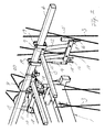
- a first and a second spreader 1, 2 are shown in side by side lift operation.
- the spreaders 1, 2 are each suspended in ropes 3 from a rope crane (not shown) and operated for shifting containers from one location to another.
- the ropes connect to an upper end of a spreader, typically via rope sheaves 4 which are journalled for rotation in a head-block comprised in the spreader structure.
- twist locks 5 are operative as coupling means for coupling and uncoupling, respectively, of the spreader and a container to be shifted.
- one of the spreaders is inactive.
- the first and second spreaders are together operated in lifting/lowering and shifting operations.
- the spreader 1 is inactive and the spreader 2 is operated in single lift operation.
- the inactive spreader 1 is held by the crane ropes in a stowage position in the lower side of a trolley, the trolley in the drawings represented by a beam 6 which is comprised in the substructure of the trolley.
- the stowed spreader 1 thus travels with the trolley in reciprocal movements along a crane beam (not shown).
- the stowed spreader 1 is docked in a stowage mechanism generally designated by reference numeral 8.
- the stowage mechanism 8 effects a displacement of the stowed spreader 1 out of the pathway for the ropes 3 that operate the active spreader 2 in lifting and lowering movements.
- the stowage mechanism 8 is arranged as a link mechanism and foldable between an extended docking position and a pivoted stowage position wherein the inactive spreader is positioned close to the trolley.
- the stowage mechanism 8 comprises a link mechanism having an upper horizontal link member 9 and a lower horizontal link member 10.
- the upper and lower link members 9, 10 are both pivotally connected to an intermediate link member.
- the upper link member 9 is arranged for docking or connecting to the trolley
- the lower link member 10 is arranged for docking or connecting to the spreader.
- the upper and lower link members 9, 10 may be interconnected through a pair of parallel link members 11 and 12, respectively.
- each spreader is associated with two corresponding mechanisms 8 arranged pivotable in parallel vertical planes, each mechanism having an upper horizontal link member 9 engaging the trolley, and a lower horizontal link member 10 engaging the spreader.
- a horizontal beam member 13 interconnects the associated stowage mechanisms 8, which are separated by the beam member to engage the subject spreader at substantially equal distances from a longitudinal centre of the spreader.
- Other configurations of a folding stowage mechanism are however conceivable.
- Each stowage mechanism 8 has a damper 14 arranged to counteract oscillations in the parallel links that may otherwise be induced from accelerations and decelerations in the driven movement of the trolley.
- the damper 14 may be hydraulic or air/gas operated, or mechanical.
- the damper 14 may additionally be effective for biasing the stowage mechanism 8 into an initial position in which the ascending spreader is receivable for docking with the stowage mechanism. From the docking position, the stowage mechanism is foldable towards a stowage position close to the lower side of the trolley. The desired folding direction is ensured by arranging the stowage mechanism to take an over-centre position in the docking mode. The over-centre position may be secured through a biasing member as discussed above, or by means arranged on the mechanism for mechanically restricting the pivotal movements of the stowage mechanism.
- the spreader In the further upwards movement of the spreader, driven by the crane ropes, the spreader engages the stowage mechanism to cause the same to pivot outwards from the docking position until a limiter 15 on the stowage mechanism engages the beam 6 in the trolley structure.
- the inactive spreader In the stowed position illustrated by spreader 1 on the left hand side of the drawing, the inactive spreader is thus positively positioned out of reach for the ropes that operate the active spreader.
- the stowing spreader engages the lower link member 10 of the stowage mechanism 8.
- a correct positioning is ensured through guides 16 which are arranged on the stowage mechanism 8 to cooperate with structural members included in the spreader structure.
- the positioning guides are supported on the spreader to capture the stowage mechanism in a docking operation.
- the positioning guides optionally effectuate a mating between coupling means 17 supported on the spreader and corresponding coupling means 18 arranged on the stowage mechanism.
- the coupling means 17 are driven and remotely controlled by the crane operator.
- the coupling means 17 may be realized as twist locks, notoriously known in the art, and may be electrically or hydraulically driven for coupling and uncoupling, respectively.
- the coupling means 18 on the stowage mechanism then obviously may be realized as seats for the twist locks, corresponding to the corner casings found on containers, e.g.
- the stowage mechanism 8 connects detachably to beam member 6 of the trolley.
- This first embodiment is illustrated in connection with spreader 2 on the right hand side of the drawing.
- the upper link member 9 is clamped to the beam by means of a bolted clamp 19.
- the stowage mechanism 8 is thus stationary on the trolley, however dismountable, and docking to the spreader in single lift operations.
- the stowage mechanism 8 connects detachably to beam member 6 of the trolley by means of remotely controllable coupling means.
- the upper link member 9 is arranged connectable to the beam member 6 through corresponding coupling means 20, such as twist locks, arranged on the trolley beam 6 or alternatively on the link member 9.
- the coupling means 20 may be remotely controllable by the crane operator in coupling and uncoupling manoeuvres, respectively.
- the alternative implementation provides for arranging the stowage mechanism 8 stationary on the spreader and docking to the trolley in single lift operations. Positioning guides may be arranged on the trolley to ensure a correct docking position for the stowage mechanism in this alternative embodiment.
- the stowage mechanism 8 by being detachably connectable to the trolley as well as to the spreader, can be lowered to the ground by means of the spreader for maintenance and repair, or for exchange by another stowage mechanism, if appropriate.
Landscapes
- Engineering & Computer Science (AREA)
- Mechanical Engineering (AREA)
- Load-Engaging Elements For Cranes (AREA)
Priority Applications (1)
| Application Number | Priority Date | Filing Date | Title |
|---|---|---|---|
| EP07121102A EP2062846A1 (de) | 2007-11-20 | 2007-11-20 | Mechanismus und Verfahren zum Verstauen eines untätigen Spreizers in einem Kran |
Applications Claiming Priority (1)
| Application Number | Priority Date | Filing Date | Title |
|---|---|---|---|
| EP07121102A EP2062846A1 (de) | 2007-11-20 | 2007-11-20 | Mechanismus und Verfahren zum Verstauen eines untätigen Spreizers in einem Kran |
Publications (1)
| Publication Number | Publication Date |
|---|---|
| EP2062846A1 true EP2062846A1 (de) | 2009-05-27 |
Family
ID=39193449
Family Applications (1)
| Application Number | Title | Priority Date | Filing Date |
|---|---|---|---|
| EP07121102A Withdrawn EP2062846A1 (de) | 2007-11-20 | 2007-11-20 | Mechanismus und Verfahren zum Verstauen eines untätigen Spreizers in einem Kran |
Country Status (1)
| Country | Link |
|---|---|
| EP (1) | EP2062846A1 (de) |
Cited By (7)
| Publication number | Priority date | Publication date | Assignee | Title |
|---|---|---|---|---|
| US20120006779A1 (en) * | 2009-03-24 | 2012-01-12 | NLS Engineering Pte Ltd | Container crane |
| CN102649529A (zh) * | 2012-02-28 | 2012-08-29 | 上海中技桩业股份有限公司 | 预制管桩行业智能行车 |
| CN103979425A (zh) * | 2014-04-24 | 2014-08-13 | 王新民 | 出缸机 |
| CN112209218A (zh) * | 2020-09-30 | 2021-01-12 | 上海富朗德机械设备有限公司 | 一种汽车车身多车型平台切换吊具切换站 |
| CN113060651A (zh) * | 2021-03-17 | 2021-07-02 | 泉州芸台科技有限公司 | 一种双吊具的电动起重机 |
| CN115258906A (zh) * | 2022-09-28 | 2022-11-01 | 中化二建集团有限公司 | 凝汽器吊装方法 |
| CN116462081A (zh) * | 2023-03-24 | 2023-07-21 | 上海二十冶建设有限公司 | 一种用于大型粗轧机机架的吊具及其使用方法 |
Citations (4)
| Publication number | Priority date | Publication date | Assignee | Title |
|---|---|---|---|---|
| US5183305A (en) * | 1989-12-18 | 1993-02-02 | Nordstrom Immo R | Method and apparatus for handling cargo containers |
| WO2001098195A1 (en) * | 2000-06-22 | 2001-12-27 | Bromma Conquip Ab | Side by side twin spreader and method |
| WO2003104132A1 (en) * | 2002-06-01 | 2003-12-18 | Stinis Beheer B.V. | Hoisting frame and method for its use |
| WO2005090223A1 (en) * | 2004-03-24 | 2005-09-29 | Nsl Engineering Pte Ltd | System for manipulating containers |
-
2007
- 2007-11-20 EP EP07121102A patent/EP2062846A1/de not_active Withdrawn
Patent Citations (4)
| Publication number | Priority date | Publication date | Assignee | Title |
|---|---|---|---|---|
| US5183305A (en) * | 1989-12-18 | 1993-02-02 | Nordstrom Immo R | Method and apparatus for handling cargo containers |
| WO2001098195A1 (en) * | 2000-06-22 | 2001-12-27 | Bromma Conquip Ab | Side by side twin spreader and method |
| WO2003104132A1 (en) * | 2002-06-01 | 2003-12-18 | Stinis Beheer B.V. | Hoisting frame and method for its use |
| WO2005090223A1 (en) * | 2004-03-24 | 2005-09-29 | Nsl Engineering Pte Ltd | System for manipulating containers |
Cited By (11)
| Publication number | Priority date | Publication date | Assignee | Title |
|---|---|---|---|---|
| US20120006779A1 (en) * | 2009-03-24 | 2012-01-12 | NLS Engineering Pte Ltd | Container crane |
| CN102649529A (zh) * | 2012-02-28 | 2012-08-29 | 上海中技桩业股份有限公司 | 预制管桩行业智能行车 |
| CN102649529B (zh) * | 2012-02-28 | 2013-12-25 | 上海中技桩业股份有限公司 | 预制管桩行业智能行车 |
| CN103979425A (zh) * | 2014-04-24 | 2014-08-13 | 王新民 | 出缸机 |
| CN103979425B (zh) * | 2014-04-24 | 2016-05-11 | 王新民 | 出缸机 |
| CN112209218A (zh) * | 2020-09-30 | 2021-01-12 | 上海富朗德机械设备有限公司 | 一种汽车车身多车型平台切换吊具切换站 |
| CN113060651A (zh) * | 2021-03-17 | 2021-07-02 | 泉州芸台科技有限公司 | 一种双吊具的电动起重机 |
| CN113060651B (zh) * | 2021-03-17 | 2023-08-08 | 泉州芸台科技有限公司 | 一种双吊具的电动起重机 |
| CN115258906A (zh) * | 2022-09-28 | 2022-11-01 | 中化二建集团有限公司 | 凝汽器吊装方法 |
| CN115258906B (zh) * | 2022-09-28 | 2022-12-02 | 中化二建集团有限公司 | 凝汽器吊装方法 |
| CN116462081A (zh) * | 2023-03-24 | 2023-07-21 | 上海二十冶建设有限公司 | 一种用于大型粗轧机机架的吊具及其使用方法 |
Similar Documents
| Publication | Publication Date | Title |
|---|---|---|
| EP2062846A1 (de) | Mechanismus und Verfahren zum Verstauen eines untätigen Spreizers in einem Kran | |
| WO2022160607A1 (zh) | 移动发电系统的箱体的运输车和安装方法 | |
| EP2133304B1 (de) | Hebekran und Offshore Schiff | |
| EP2559614B1 (de) | Schiff und Verfahren zum Entfernen und/oder Installieren von mindestens einem Teil einer Meeresplattform | |
| US9371657B2 (en) | Working device with stationary boom and rotary head | |
| WO2004020275A2 (en) | Multipurpose tower for monohull | |
| CN110446678B (zh) | 提升运输集装箱 | |
| EP3695091B1 (de) | Vorrichtung, system und verfahren zum transportieren und installieren eines bop-stapels für eine onshore-bohranlage | |
| US10099905B2 (en) | Crane | |
| CN209456035U (zh) | 一种钢拱架安装作业平台 | |
| KR101507626B1 (ko) | 지게차의 안전작업을 위한 카메라 장치 | |
| CN106703718A (zh) | 抽油杆起下装置及抽油杆起下系统 | |
| KR20150125934A (ko) | 정지된 마스트 및 회전식 헤드를 가진 작업 장치 | |
| JP2617276B2 (ja) | 吊上げ装置における装着方法 | |
| KR20150040461A (ko) | 선박용 앵커 체인 컴프레서의 위치 조정장치 | |
| CN110536857B (zh) | 船对岸起重机 | |
| KR102813924B1 (ko) | 도크측 컨테이너 크레인용 붐 확장 장치 및 그 확장 방법 | |
| EP1857401A1 (de) | Spreizer Vorrichtung und Positionierung Mitteln | |
| CN110696976A (zh) | 起重船及起重作业方法 | |
| CN214059676U (zh) | 塔式起重机 | |
| CN116096631B (zh) | 用于船舶的车辆舱板质量升降系统 | |
| US10807840B2 (en) | Counterweight device and construction machine | |
| CN201326381Y (zh) | 顶部对接式石油钻机井架 | |
| GB2322350A (en) | Vehicle Cranes | |
| CN112224334B (zh) | 一种海上滑移装置 |
Legal Events
| Date | Code | Title | Description |
|---|---|---|---|
| PUAI | Public reference made under article 153(3) epc to a published international application that has entered the european phase |
Free format text: ORIGINAL CODE: 0009012 |
|
| AK | Designated contracting states |
Kind code of ref document: A1 Designated state(s): AT BE BG CH CY CZ DE DK EE ES FI FR GB GR HU IE IS IT LI LT LU LV MC MT NL PL PT RO SE SI SK TR |
|
| AX | Request for extension of the european patent |
Extension state: AL BA HR MK RS |
|
| AKX | Designation fees paid | ||
| REG | Reference to a national code |
Ref country code: DE Ref legal event code: 8566 |
|
| STAA | Information on the status of an ep patent application or granted ep patent |
Free format text: STATUS: THE APPLICATION IS DEEMED TO BE WITHDRAWN |
|
| 18D | Application deemed to be withdrawn |
Effective date: 20091128 |