EP2063006A2 - Dispositif et procédé pour finir les bobines d'un métier à filer à anneaux avant leur transfert vers le bobinage automatique - Google Patents
Dispositif et procédé pour finir les bobines d'un métier à filer à anneaux avant leur transfert vers le bobinage automatique Download PDFInfo
- Publication number
- EP2063006A2 EP2063006A2 EP20080169557 EP08169557A EP2063006A2 EP 2063006 A2 EP2063006 A2 EP 2063006A2 EP 20080169557 EP20080169557 EP 20080169557 EP 08169557 A EP08169557 A EP 08169557A EP 2063006 A2 EP2063006 A2 EP 2063006A2
- Authority
- EP
- European Patent Office
- Prior art keywords
- yarn
- bobbin
- tube
- bobbins
- ring
- Prior art date
- Legal status (The legal status is an assumption and is not a legal conclusion. Google has not performed a legal analysis and makes no representation as to the accuracy of the status listed.)
- Withdrawn
Links
- 238000004804 winding Methods 0.000 title claims abstract description 39
- 238000007378 ring spinning Methods 0.000 title claims abstract description 18
- 238000000034 method Methods 0.000 title claims description 15
- 238000009987 spinning Methods 0.000 claims abstract description 40
- 238000002360 preparation method Methods 0.000 claims description 31
- 230000008021 deposition Effects 0.000 claims description 4
- 238000007664 blowing Methods 0.000 claims description 3
- 230000002093 peripheral effect Effects 0.000 claims description 2
- 238000004519 manufacturing process Methods 0.000 abstract description 5
- 230000001419 dependent effect Effects 0.000 description 2
- 230000001174 ascending effect Effects 0.000 description 1
- 230000007547 defect Effects 0.000 description 1
- 230000008030 elimination Effects 0.000 description 1
- 238000003379 elimination reaction Methods 0.000 description 1
- 239000012528 membrane Substances 0.000 description 1
- 230000004048 modification Effects 0.000 description 1
- 238000012986 modification Methods 0.000 description 1
- 230000000630 rising effect Effects 0.000 description 1
- 238000004904 shortening Methods 0.000 description 1
- 238000006467 substitution reaction Methods 0.000 description 1
Images



Classifications
-
- D—TEXTILES; PAPER
- D01—NATURAL OR MAN-MADE THREADS OR FIBRES; SPINNING
- D01H—SPINNING OR TWISTING
- D01H1/00—Spinning or twisting machines in which the product is wound-up continuously
- D01H1/14—Details
- D01H1/38—Arrangements for winding reserve lengths of yarn on take-up packages or spindles, e.g. transfer tails
Definitions
- the present invention refers to a device and a process for the preparation of bobbins to feed to the winding stage.
- the yarn production technique is widely prevalent that includes a first stage of ring spinning which produces bobbin yarn, followed by a second winding stage in which the yarn is unwound from its bobbin, cleaned of its defects and rewound in a package, which contains a much greater yarn quantity and which corresponds to a considerable number of processed bobbins.
- the winding processing is much faster than the spinning, and thus a small quantity of spinning stations or units, on the order of several dozens, is capable of completing the production of a great number of ring spinning units, on the order of several thousand.
- a spinning frame is coupled to a winder having hourly winding capacity that considerably exceeds the spinning capacity of the spinning frame, so to complete, with a certain margin, the entire spinning production without dead times.
- the bobbins which come from the spinning frame have the terminal part of their yarn wound a specific number of turns around the package of the bobbin or its base.
- the preparation of the bobbin is carried out on the winder, before being fed to one of the winding stations which compose the automatic winder, with a processing which is carried out in several steps.
- the terminal part of the yarn on the bobbin must be drawn, freeing it from the base of the tube and unwinding it from the outer surface of the bobbin for a certain length.
- the yarn is then cut to length and inserted in the upper end of its tube, from which the winding station - at the start of the unwinding of every new bobbin fed thereto - can draw it, join it with the terminal yarn tail of the preceding bobbin, available on the package, and then restart the winding until the package being processed is completed. Still generally speaking, such preparation is requested both for the new bobbins coming from the spinning frame and for the few bobbins not completely unwound, if they had significant residual yarn still wound thereon that is worth recovering.
- the preparation stations of the bobbins in the context of the winder thus require a certain time interval for every bobbin to be prepared, and thus they limit the winding capacity.
- the winders constituted by many winding units they require a plurality of preparation stations for each winder; this is particularly the case for the yarn-winders which must wait every time for the doffing of the bobbins from the spinning frame connected thereto in order to restart the processing.
- the multiplication of the preparation units of the bobbins situated on each winder significantly increases their overall length, the transport circuits and consequently machine costs.
- the present invention is aimed for the preparation of the bobbins already in the final step of the ring spinning, before being sent to the winding stage which is connected to the spinning frame.
- the invention is herein described with reference to a typical embodiment thereof in a ring spinning station.
- the present invention in its bobbin preparation process meaning before bobbin doffing and winder transfer, is defined in claim 9. Its preferred embodiments or variants are defined in the dependent claims 10-13. The latter claims regard the application of the invention in a yarn-winder.
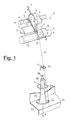
- every spinning frame is composed of a plurality of spinning stations aligned along its faces. Every spinning face is composed of hundreds of such stations, which commonly derive their driving from motors which actuate along longitudinal axes, and their functions from dispenser units which distribute them along the machine.
- the sliver 1 comes from a package hung above the spinning station, not indicated in the figure for the sake of simplicity, and is first brought forward to the drafting unit 2.
- This generally consists of a plurality of driving members of the sliver at increasing linear speeds; such driving members gradually refine such sliver by making the fibres which compose it slide between them.
- the drafting group is depicted, as an example, with an initial pair of belts 3 and 4, of which the lower belt 3 is driven into movement by a knurled segment 5 of a longitudinal bar 6, in common with the adjacent spinning stations and rotating in accordance with the arrow a).
- the path of the lower belts 3 is approximately triangular and determined by a common terminal bar 7 which is longitudinally extended.
- the upper belt 4 is idle and is driven in movement in accordance with the arrow b) by the lower belt 3, on which it is pressed by an overlying support, not indicated in the figure for the sake of simplicity.
- the path of the upper belt 4 is also approximately triangular and determined by a roller 8 and by a fixed terminal bar 9.
- a pair of drafting rollers 11,12 is placed, which impart the final drafting to the sliver, since they are provided with a linear speed greater than that of the preceding belts 3,4.
- the lower roller is composed of a grooved segment 11 of a longitudinal bar 13, shared with the adjacent spinning stations and rotating in accordance with the arrow c).
- the upper counter-roller 12 is idle and it too is pressed by a overhanging support means (not shown in the drawings), against the roller segment 11, which drives it in rotation in accordance with the arrow d), with the refined sliver interposed between them, and which gives rise to the yarn 20.
- the yarn 20 first passes into the fixed thread guides 21, typically in pig's tail form, and from here into the rotating small ring 22, which rotates on a fixed ring 23 borne by a ring-carrier platform 24, shared with the adjacent spinning units, continuously moved in accordance with the arrow e) in two directions, so to continuously raise and lower all the fixed rings 23 of the single spinning units and to distribute the yarn winding on every bobbin 25 wound on its tube 26.
- the tube 26 is fit on the underlying rotating spindle 30, which is driven into rotation at high speeds, currently in the range of 10,000-20,000 rev/min. In general, such driving is carried out with longitudinal drive belts which slide engaged on the lower part 31 of the bobbin carrier spindle 30, shown in the subsequent figures 2-4 .
- the yarn 20 rotates in a whirling manner around the bobbin, forming the so-called "balloon" due to the centrifugal force.
- the balloon causes a significant stress on the yarn 20, and can be limited with a containment ring 28, in general of greater diameter than the size of the bobbin 25.
- the balloon containment ring 28 is firmly mounted on a platform thereof capable of vertical travel movements, which however maintain it above the level of the platform 24.
- the twisting of the yarn is caused by the rotation of the bobbin 25 and is spread, together with the related stresses, rising up to the point at which the sliver of the yarn 20 is released by the final draft drums 11,12.
- the object of such bobbin winding method is essentially that of giving a tapered shape to the bobbin, so that the bobbin results compact, so that it does not break up during its unwinding, and so that the yarn is unwound, substantially unwinding layer-by-layer from its upper conical part.
- the bobbin carrier spindle 30 is made with the following modes. It comprises:
- the length of the part projecting from the terminal part 35 can be limited in the range of 8-15 mm, which is sufficient for the purpose of winding and holding yarn coils during the lifting of the completed bobbin.
- its cylindrical surface can be made with variants for modifying the adhesion of the wound yarn, shown in figure 6 .
- the ring-carrier platform 24 is provided with actuation which allows lifting until it brings the yarn 20 to be bound on the terminal part 35 of the bobbin carrier spindle 30.
- the preparation of the bobbin is carried out as follows.
- the spinning process on the ring spinning frame is governed by a governing and controlling unit, which detects the achievement of the quantity of yarn in meters produced in bobbins 25 on every spinning frame unit.
- Such unit starts the bobbin completion process, before proceeding with the doffing of the completed bobbins 25 and their substitution with a new tube 26, on which a new bobbin will have to be wound, operating in parallel over all the spinning units which compose the ring spinning frame.
- the spinning frame is provided with a doffing device that is capable of being to lifted so to simultaneously grasp all the completed bobbins 25 over all the spinning units, with a series of individual clamps which are brought to take the bobbins, to lift themselves, taking the bobbins from the bobbin carrier spindles 30 on which they are fit, and then to be lowered so to deposit them on the individual supports which constitute the transport system of the yarn-winder.
- the same device then provides for taking the empty tubes 26 and fitting them on the bobbin carrier spindles freed from the bobbins 25 in the preceding operation.
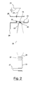
- the first preparation stage of the completed bobbins 25 is shown in figure 2 : the ring-carrier platform 24 is lifted to a maximum level in order to bring the rotating small ring 22 to deposit a winding 40 of yarn 20 on the upper terminal part 35 of the bobbin carrier spindle 30.
- a small number of coils of the winding 40 will suffice. The length of such winding will then be available so to be inserted inside the tube 26 of the doffed bobbin.
- the bobbin is finished with the normal binding to the base of the tube 26.
- the ring-carrier platform 24 is lowered to a minimum level, in order to bring the rotating small ring 22 to deposit a winding 41 of yarn 20 on the ring nut of the part 32 on which the bobbin is abutted.
- a number of coils of the winding 41 will suffice, in the range of 5-10. All the bobbin carrier spindles 30 are stopped and the spinning is interrupted, beginning the actual doffing operation.
- the ring-carrier platform 24 is then locked in the lowest position.
- the clamp 45 is brought to grasp the upper part of the tube of the bobbin 25 and to lift itself, taking the bobbin 25 off from the bobbin carrier spindle 30.
- the clamp 45 is composed of a rigid cylindrical ring 46, having an annular chamber 47 at its interior that can be inflated with compressed air.
- the clamp 45 can thus be provided for engaging the body of yarn wound on the completed bobbin 25 or the upper part of its tube 26 free from the wound yarn.
- the transverse size of the annular chamber 47 is determined such that, with non-inflated chamber, it can be easily inserted or taken off the body of the completed bobbin 25 or from its tube 26.
- the re-inflating with compressed air of the chamber 47 locks the bobbin 25 and allows lifting it and moving it by exerting the necessary forces, while the release of the compressed air allows freeing it after movement.
- the clamp 45 has locked the upper part of the bobbin 25 and it has been raised to an intermediate point of its lifting travel so to remove the bobbin 25 from the bobbin carrier spindle 30.
- the thread guide 21 is lifted so to prevent interferences with the doffing.
- the yarn 20 is held on one side of the bobbin 25 clamped by the clamp 45, and on the other side it is bound to the ring nut of the part 32 of the bobbin carrier spindle 30. Due to the lifting pull exerted by the clamp 45, the yarn 20 is broken in an intermediate point between clamp and ring nut.
- the bobbin 25 is removed from the bobbin carrier spindle 30 and the yarn winding 40 on its terminal part 35 is freed, falling inside the tube 26, the start of the bobbin unwinding thus remaining available at the start of its winding.
- the bobbin 25 doffed from its bobbin carrier spindle 30 is then deposited on one of the peg support pins which act as a carrier of the full bobbins and the empty tubes.
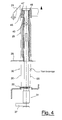
- the clamp 45 operates on the top of the tube 26 - as shown in figure 4 - and is provided with a blowing nozzle (not shown in the figure for the sake of simplicity).
- a blowing nozzle not shown in the figure for the sake of simplicity.
- the bobbin carrier spindle 30 is shown which has received the new tube 26 for starting the production of the new bobbin.
- the yarn tail coming from the drafting group 2 passes through the small ring 22 and is bound to the ring nut 32. From here, the yarn tail of the winding 41 can be retaken, for once again starting the spinning on the changed tube.
- the variant A shows the cylindrical terminal part 35 machined with opening 51 slightly hollow in order to determine the deposition level of the winding 40.
- the variant B shows the cylindrical terminal part 35 made rougher in its peripheral part 52, for example machined with knurling, in order to favour the adhesion of the yarn 20 coils at the desired level.
- the variant C shows the cylindrical terminal part 35 of modifiable length. It can be made removable or substitutable with respect to the underlying cylindrical part 33.
- the part 35 is mounted with a thread 55 or with an equivalent mechanical connection.
- the same terminal part 35 can be raised or lowered with respect to the underlying part 33, by screwing it or unscrewing it from its thread 55, possibly inserting thicknesses of collar form.
- the variant C allows adapting the ring spinning frame to processing with tubes 26 of different length, in order to produce yarn batches wound on bobbins 25 that are larger or smaller.
- terminal parts 35 of suitable length can be prepared on the bobbin carrier spindles 30 in the ring spinning units, such parts 35 making the projection level of said terminal part consistent with the length of the new tubes to be used.
- the plurality of the bobbins 25 - with their terminal yarn end inserted in the tube - is then delivered to the transport circuit for their sending to the winder.
- the winder is thus fed with new, already-ready bobbins which can immediately used without delay.
- the small part of rejected bobbins and those not completed by the spinning units can be prepared in an out-of-production-line transport branch, without affecting the normal winding process, by an auxiliary preparation unit which does not have to respect restricted time limits and can work with the best yield and maximum reliability.
Landscapes
- Engineering & Computer Science (AREA)
- Mechanical Engineering (AREA)
- Textile Engineering (AREA)
- Replacing, Conveying, And Pick-Finding For Filamentary Materials (AREA)
- Finish Polishing, Edge Sharpening, And Grinding By Specific Grinding Devices (AREA)
- Spinning Or Twisting Of Yarns (AREA)
Applications Claiming Priority (1)
| Application Number | Priority Date | Filing Date | Title |
|---|---|---|---|
| ITMI20072207 ITMI20072207A1 (it) | 2007-11-21 | 2007-11-21 | Dispositivo e procedimento per la finitura delle spole da alimentare dai filatoi ad anello alla roccatura automatica |
Publications (1)
| Publication Number | Publication Date |
|---|---|
| EP2063006A2 true EP2063006A2 (fr) | 2009-05-27 |
Family
ID=40314737
Family Applications (1)
| Application Number | Title | Priority Date | Filing Date |
|---|---|---|---|
| EP20080169557 Withdrawn EP2063006A2 (fr) | 2007-11-21 | 2008-11-20 | Dispositif et procédé pour finir les bobines d'un métier à filer à anneaux avant leur transfert vers le bobinage automatique |
Country Status (3)
| Country | Link |
|---|---|
| EP (1) | EP2063006A2 (fr) |
| CN (1) | CN101440539B (fr) |
| IT (1) | ITMI20072207A1 (fr) |
Cited By (1)
| Publication number | Priority date | Publication date | Assignee | Title |
|---|---|---|---|---|
| KR101468823B1 (ko) * | 2013-12-23 | 2014-12-03 | 정주옥 | 커버링용 스핀들 장치 |
Families Citing this family (6)
| Publication number | Priority date | Publication date | Assignee | Title |
|---|---|---|---|---|
| CN104131378A (zh) * | 2014-08-08 | 2014-11-05 | 湖州市菱湖石淙永盛丝织厂 | 一种锭杆长度可变的纺织锭子 |
| DE102014017818A1 (de) * | 2014-12-03 | 2016-06-09 | Saurer Germany Gmbh & Co. Kg | Verfahren zur Herstellung und Weiterverarbeitung eines Spinnkopses |
| CN111676555A (zh) * | 2020-06-08 | 2020-09-18 | 山东祥瑞祥纺织有限公司 | 变支在59tex以上密度纱自动落纱环节中的应用 |
| CH717807A1 (de) * | 2020-09-02 | 2022-03-15 | Rieter Ag Maschf | Spinnstelle einer Ringspinnmaschine, Ringspinnmaschine und Verfahren zum Betreiben einer Spinnstelle einer Ringspinnmaschine. |
| CN112877824B (zh) * | 2020-09-22 | 2025-05-09 | 武汉纺织大学 | 一种螺纹调控纤维成纱的纺纱方法及其纺纱装置 |
| CN113430683A (zh) * | 2021-07-13 | 2021-09-24 | 湖北天门纺织机械股份有限公司 | 一种用于制造便于寻头管纱的细纱机系统及其控制方法 |
Family Cites Families (5)
| Publication number | Priority date | Publication date | Assignee | Title |
|---|---|---|---|---|
| DE10053756A1 (de) * | 2000-10-30 | 2002-05-08 | Rieter Ag Maschf | Spinnmaschine |
| JP4284863B2 (ja) * | 2000-12-07 | 2009-06-24 | 株式会社豊田自動織機 | 紡機における尻糸切断方法及び尻糸切断装置 |
| EP1791992B1 (fr) * | 2004-09-03 | 2010-11-03 | Titan Paints & Chemicals Limited | Support de bobine rotative |
| DE102004060601A1 (de) * | 2004-12-08 | 2006-06-22 | Spindelfabrik Süssen Schurr Stahlecker & Grill GmbH | Verfahren zum Bestücken von Spindeln einer Ringspinnmaschine mit Spulenhülsen |
| CN2873813Y (zh) * | 2006-01-04 | 2007-02-28 | 东台纺织机械有限责任公司 | 细纱机集体落纱装置的握纱器 |
-
2007
- 2007-11-21 IT ITMI20072207 patent/ITMI20072207A1/it unknown
-
2008
- 2008-11-20 EP EP20080169557 patent/EP2063006A2/fr not_active Withdrawn
- 2008-11-21 CN CN2008101786158A patent/CN101440539B/zh not_active Expired - Fee Related
Cited By (1)
| Publication number | Priority date | Publication date | Assignee | Title |
|---|---|---|---|---|
| KR101468823B1 (ko) * | 2013-12-23 | 2014-12-03 | 정주옥 | 커버링용 스핀들 장치 |
Also Published As
| Publication number | Publication date |
|---|---|
| CN101440539A (zh) | 2009-05-27 |
| ITMI20072207A1 (it) | 2009-05-22 |
| CN101440539B (zh) | 2012-05-09 |
Similar Documents
| Publication | Publication Date | Title |
|---|---|---|
| EP2063006A2 (fr) | Dispositif et procédé pour finir les bobines d'un métier à filer à anneaux avant leur transfert vers le bobinage automatique | |
| CN1028039C (zh) | 在气流纺纱装置中连接纱线的方法和装置 | |
| CN103014960B (zh) | 纺纱机和用于中断纺纱机的纱线制造的方法 | |
| CN103648941B (zh) | 筒管卷缠机 | |
| USRE34170E (en) | Spinning unit piecing process for producing feed spools | |
| CN101328628B (zh) | 高速半自动转杯纺纱机 | |
| CN112695424A (zh) | 一种环锭纺细纱纺纱过程中断纱的处理方法 | |
| US10472740B2 (en) | Textile machine and method for operating same | |
| CS275675B6 (en) | Process for removing spots of a yarn extensions and apparatus for making the same | |
| EP2083102A2 (fr) | Dispositif et processus pour le dégarnissage des bobines des métiers à filer à anneaux | |
| US3903681A (en) | Apparatus for connecting two or more working operations in the production, preparation or finishing of yarns | |
| JP7139093B2 (ja) | エアジェット紡績機上の紡績工程の再開の方法、及びその方法を実施するためのエアジェット紡績機 | |
| CN100436672C (zh) | 气流纺纱机上重新开始组分纱线纺纱的方法和实现该方法的装置 | |
| JP3594703B2 (ja) | ポット・スピニング装置におけるスピニング・ケークの巻返し法 | |
| US5865022A (en) | Method and apparatus for piecing a broken yarn at an open end spinning station | |
| EP1225258B1 (fr) | Procédé pour fabriquer des filés de fibres | |
| US5010724A (en) | Method and apparatus for producing packages | |
| EP1524229B1 (fr) | Dispositif et procédé pour déposer la réserve de fil sur les canettes de métiers à filer à bout libre | |
| US4843809A (en) | Method of automatically exchanging spinning bobbin tubes in a spinning machine | |
| GB1214062A (en) | Methods and apparatus for servicing textile machines | |
| EP0698678B1 (fr) | Procédé et appareil pour la rupture de la mèche envidée sur les bobines d'un métièr à filer à ailettes et pour attacher l'extrémité de la mèche sur la bobine avant la levée automatique des bobines | |
| CN101935897A (zh) | 用于操作工位的方法和自由端转杯纺纱机的工位 | |
| CN112703279A (zh) | 操作环锭纺纱机的维护机器人的方法 | |
| CN110158206A (zh) | 离心式精纺方法和离心式细纱机 | |
| JP2017089090A (ja) | エアジェット紡績機上の紡績工程を再開させるためワークステーションを準備する方法、及びその方法を実施するためのエアジェット紡績機 |
Legal Events
| Date | Code | Title | Description |
|---|---|---|---|
| PUAI | Public reference made under article 153(3) epc to a published international application that has entered the european phase |
Free format text: ORIGINAL CODE: 0009012 |
|
| AK | Designated contracting states |
Kind code of ref document: A2 Designated state(s): AT BE BG CH CY CZ DE DK EE ES FI FR GB GR HR HU IE IS IT LI LT LU LV MC MT NL NO PL PT RO SE SI SK TR |
|
| AX | Request for extension of the european patent |
Extension state: AL BA MK RS |
|
| STAA | Information on the status of an ep patent application or granted ep patent |
Free format text: STATUS: THE APPLICATION IS DEEMED TO BE WITHDRAWN |
|
| 18D | Application deemed to be withdrawn |
Effective date: 20120601 |