EP2063038A2 - Elément d'absorbeur plafonnier - Google Patents
Elément d'absorbeur plafonnier Download PDFInfo
- Publication number
- EP2063038A2 EP2063038A2 EP08166761A EP08166761A EP2063038A2 EP 2063038 A2 EP2063038 A2 EP 2063038A2 EP 08166761 A EP08166761 A EP 08166761A EP 08166761 A EP08166761 A EP 08166761A EP 2063038 A2 EP2063038 A2 EP 2063038A2
- Authority
- EP
- European Patent Office
- Prior art keywords
- foam
- absorber element
- frame
- ceiling
- sound
- Prior art date
- Legal status (The legal status is an assumption and is not a legal conclusion. Google has not performed a legal analysis and makes no representation as to the accuracy of the status listed.)
- Withdrawn
Links
- 239000006096 absorbing agent Substances 0.000 title claims description 32
- 239000000725 suspension Substances 0.000 claims abstract description 24
- 238000010521 absorption reaction Methods 0.000 claims abstract description 11
- 239000006260 foam Substances 0.000 claims description 67
- 230000002093 peripheral effect Effects 0.000 claims description 4
- 229920000877 Melamine resin Polymers 0.000 claims description 3
- 239000004640 Melamine resin Substances 0.000 claims description 3
- 239000011148 porous material Substances 0.000 claims 1
- 239000006261 foam material Substances 0.000 abstract 2
- 239000000463 material Substances 0.000 abstract 1
- 229910052782 aluminium Inorganic materials 0.000 description 2
- XAGFODPZIPBFFR-UHFFFAOYSA-N aluminium Chemical compound [Al] XAGFODPZIPBFFR-UHFFFAOYSA-N 0.000 description 2
- 239000007769 metal material Substances 0.000 description 2
- 241001295925 Gegenes Species 0.000 description 1
- 230000015572 biosynthetic process Effects 0.000 description 1
- 210000004072 lung Anatomy 0.000 description 1
- 230000003287 optical effect Effects 0.000 description 1
Images




Classifications
-
- E—FIXED CONSTRUCTIONS
- E04—BUILDING
- E04F—FINISHING WORK ON BUILDINGS, e.g. STAIRS, FLOORS
- E04F13/00—Coverings or linings, e.g. for walls or ceilings
- E04F13/07—Coverings or linings, e.g. for walls or ceilings composed of covering or lining elements; Sub-structures therefor; Fastening means therefor
- E04F13/08—Coverings or linings, e.g. for walls or ceilings composed of covering or lining elements; Sub-structures therefor; Fastening means therefor composed of a plurality of similar covering or lining elements
- E04F13/0801—Separate fastening elements
- E04F13/0803—Separate fastening elements with load-supporting elongated furring elements between wall and covering elements
- E04F13/0805—Separate fastening elements with load-supporting elongated furring elements between wall and covering elements with additional fastening elements between furring elements and the wall
-
- E—FIXED CONSTRUCTIONS
- E04—BUILDING
- E04B—GENERAL BUILDING CONSTRUCTIONS; WALLS, e.g. PARTITIONS; ROOFS; FLOORS; CEILINGS; INSULATION OR OTHER PROTECTION OF BUILDINGS
- E04B9/00—Ceilings; Construction of ceilings, e.g. false ceilings; Ceiling construction with regard to insulation
- E04B9/04—Ceilings; Construction of ceilings, e.g. false ceilings; Ceiling construction with regard to insulation comprising slabs, panels, sheets or the like
- E04B9/0428—Ceilings; Construction of ceilings, e.g. false ceilings; Ceiling construction with regard to insulation comprising slabs, panels, sheets or the like having a closed frame around the periphery
-
- E—FIXED CONSTRUCTIONS
- E04—BUILDING
- E04B—GENERAL BUILDING CONSTRUCTIONS; WALLS, e.g. PARTITIONS; ROOFS; FLOORS; CEILINGS; INSULATION OR OTHER PROTECTION OF BUILDINGS
- E04B9/00—Ceilings; Construction of ceilings, e.g. false ceilings; Ceiling construction with regard to insulation
- E04B9/04—Ceilings; Construction of ceilings, e.g. false ceilings; Ceiling construction with regard to insulation comprising slabs, panels, sheets or the like
- E04B9/0464—Ceilings; Construction of ceilings, e.g. false ceilings; Ceiling construction with regard to insulation comprising slabs, panels, sheets or the like having irregularities on the faces, e.g. holes, grooves
-
- E—FIXED CONSTRUCTIONS
- E04—BUILDING
- E04B—GENERAL BUILDING CONSTRUCTIONS; WALLS, e.g. PARTITIONS; ROOFS; FLOORS; CEILINGS; INSULATION OR OTHER PROTECTION OF BUILDINGS
- E04B9/00—Ceilings; Construction of ceilings, e.g. false ceilings; Ceiling construction with regard to insulation
- E04B9/34—Grid-like or open-work ceilings, e.g. lattice type box-like modules, acoustic baffles
Definitions
- the invention relates to a ceiling absorber element, comprising a frame part, which on one side has a sound-permeable, continuous closed and level aligned sound entrance surface, wherein the rear side of the sound entrance surface foam members are arranged for sound absorption.
- Absorber elements of the type in question are known. These are used for sound absorption, especially in enclosed spaces and have fastening means for fixing the absorber element to the ceiling.
- the foam parts are interrupted along two running between opposite frame rails suspension rails to form separate, block-like foam elements.
- the suspension rails are accordingly preferably part of the ceiling absorber element and are at least partly in a position of concealment within the frame part rear region of the absorber element in the absorber space defined by the foam part.
- the foam part is interrupted accordingly to form block-like foam elements, further wherein the foam part or the block-like foam elements has a height considered perpendicular to the surface extension of the absorber element, which corresponds to a multiple of measured in the same direction height of the suspension rails.
- the ceiling absorber element can be arranged close to the ceiling, furthermore possibly without gaps.
- the block-like foam elements Moreover, further form a one-piece foam part, so that further, a continuous sound entry surface aligned with the frame part is given by the foam part.
- the suspension rails are hereby preferably in valley-shaped incisions between two block-like, adjacent foam elements.
- the suspension rails are screw-connected to the frame part, this more preferably with the interposition of the remaining between the block-like foam elements foam section, which on the connection of suspension rails and frame part at the same time the foam part is fixed.
- the foam part has three foam elements, each with suspended between two adjacent foam elements suspension rails.
- the foam elements can in this case further considered transversely to the orientation of the suspension rails have the same widths. Alternatively, different widths may be provided in this respect.
- the outer, ie peripheral foam elements are the same width, while in a preferred embodiment with three foam elements, the middle foam element has a respect to the edge-side foam elements about twice the width.
- At least two of the foam elements are chamfered along mutually parallel frame sides in such a way that they drop toward the edge which is not overstressed. Accordingly, a skew starting from the frame part in the direction of the installed state of the ceiling facing side is given, which offers both optical advantages at the same time an enlargement of the lateral, over the frame part projecting freely towards the ceiling absorption surface.
- the height of a foam element which extends rearwardly beyond the frame corresponds to two or more times the frame width, so more preferably approximately 2 to 10 times, more preferably approximately 2 to 4 times the frame width or the frame height measured in the height direction of the foam element.
- this angle is about 5 ° to 75 ° to a perpendicular to the sound entrance surface. In a preferred embodiment, this angle is about 30 ° to 60 °, more preferably 45 °, this further each inclination of the chamfer to the element interior.
- the indicated numerical bandwidths also include all intermediate values, if not already indicated by way of example anyway, in particular in 1/10 steps, further in 1/10 steps from the lower and / or upper limit to the respective other limit limited.
- "And” stands for the fact that both borders are shifted by one or more tenths to the limit, i. can be limited.
- the foam element consists of an open-cell foam.
- the foam element may also consist of a melamine resin foam.
- the proposed absorber element is designed as a broadband absorber.
- an absorber element according to the invention with a length of 2,500 mm, a width of 1,250 mm and a thickness of 80 mm at a frequency of about 100 Hz has a sound absorption coefficient of about 0.5, in a frequency range of about 91 to about 150 Hz, a sound absorption level of about 0.51 to 1.0, in a frequency range of about 151 to about 600 Hz, and in a frequency range of about 1.601 to 5000 Hz a sound absorption of about 1.01 to 1.5 and in a frequency range from about 601 Hz to about 1,600 Hz, a sound absorption level of about 1.51 to about 1.7.
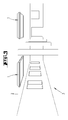
- a ceiling absorber element 1 for placement on a ceiling 2 of a room 3.
- the absorber element 1 shown in the embodiment has a square outline with an edge length of about 1250 mm.
- the absorber element 1 may also have a rectangular ground plan, so for example. Having a length of 2,500 mm and a width of 1,250 mm.
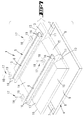
- the absorber element 1 is, as further example. From the perspective view in Fig. 7 to recognize, essentially of a frame part 4, a foam part 5 and two suspension rails. 6
- the frame part 4 is formed from a circumferential support profile, consisting of a metal material, in particular aluminum.
- the support profile is L-shaped in cross-section, with legs which have approximately equal lengths, so in the illustrated embodiment about 10 mm.
- the profile forms a support leg 7 oriented horizontally in the installed state and a frame leg 8 aligned perpendicular thereto.
- the free peripheral edge of the surrounding support leg 7 pointing inwards leaves a window 9.
- the frame part 4 comprises the foam part 5, which has a plan contour adapted to the inner contour of the frame part 4 or the surrounding frame leg 8. Correspondingly, the foam part 5 rests circumferentially on the support leg 7 of the frame part 4.
- the foam part 5 consists in the illustrated embodiment of a melamine resin foam and has a perpendicular to the surface of the support leg 7 measured height a, which corresponds to about 3.5 times the height measured in the same direction of the frame leg 8.
- the foam part 5 is provided with two incisions 10 extending parallel to these frame sides. These are in cross section as shown in FIG Fig. 6 in approximately rectangular shape with respect to the side facing away from the frame part 4 surface of the foam part 5 opening. To the frame part side surface of the foam part 5 through each incision 10 ends at a distance, this correspondingly leaving a continuous foam part bridge section 11. Accordingly, the frame part 4 facing and exposed through the window 9 foam part surface is designed as a closed, level aligned sound entrance surface 12.
- the foam part 5 is divided into three separate, block-like foam elements 13, 14, which are connected together under integral formation on the bridge sections 11.
- the arrangement and opening width of the incisions 10 is in this case selected so that the width of the two edge-side foam elements 13 measured transversely to the height extent of the foam part 5 is the same and the corresponding width of the middle foam element 14 corresponds approximately to 2 times an edge-side foam element 13.
- edge-side foam elements 13 are chamfered along the associated, parallel frame leg 8, this further, starting from a plane spanned by the free edge of the peripheral frame leg 8 level towards the element interior. This concludes the created Chamfer 15 an angle ⁇ of 45 ° to a perpendicular to the sound inlet surface 12 a.
- the incisions 10 have a free width, which is adapted to the cross-sectional width of the male suspension rails 6.
- the suspension rails 6 are designed in cross-section approximately C-shaped, with a C-opening facing the incision opening.
- the rails are made equal to the frame part 4 of a metal material, further example. Of aluminum and extend over the inside width between two leg inner sides of the transverse to the suspension rails 6 aligned, parallel frame legs 8. Accordingly, end portions of the suspension rails 6 in a projection on the Support leg 7 of the frame part 4 in coverage to portions of the frame legs. 8
- the incisions 10 extend continuously in their longitudinal extension, opening towards the respective edge surfaces of the foam part 5.
- the suspension rails 6 have a height measured perpendicular to the plane of the sound entrance surface 12, which corresponds to approximately one quarter of the height of the incisions 10 measured in the same direction. Accordingly, the suspension rails 6 positioned in a lowered position in the recesses 10 between the foam elements 13 and 14.
- the cover-side determination is carried out via fixing elements 17 anchored on the ceiling side. These have a rod-shaped mounting portion 18, to which an end adapted to the free cross section of the suspension rails 6, shoe-like support portion 19 is attached. Suspending the ceiling absorber element 1 is effected by sliding it sideways while inserting the support sections 19 into the suspension rails 6.
Landscapes
- Engineering & Computer Science (AREA)
- Architecture (AREA)
- Civil Engineering (AREA)
- Structural Engineering (AREA)
- Physics & Mathematics (AREA)
- Electromagnetism (AREA)
- Building Environments (AREA)
Applications Claiming Priority (1)
| Application Number | Priority Date | Filing Date | Title |
|---|---|---|---|
| DE200720016382 DE202007016382U1 (de) | 2007-11-22 | 2007-11-22 | Decken-Absorberelement |
Publications (2)
| Publication Number | Publication Date |
|---|---|
| EP2063038A2 true EP2063038A2 (fr) | 2009-05-27 |
| EP2063038A3 EP2063038A3 (fr) | 2012-10-10 |
Family
ID=40433309
Family Applications (1)
| Application Number | Title | Priority Date | Filing Date |
|---|---|---|---|
| EP08166761A Withdrawn EP2063038A3 (fr) | 2007-11-22 | 2008-10-16 | Elément d'absorbeur plafonnier |
Country Status (2)
| Country | Link |
|---|---|
| EP (1) | EP2063038A3 (fr) |
| DE (1) | DE202007016382U1 (fr) |
Cited By (1)
| Publication number | Priority date | Publication date | Assignee | Title |
|---|---|---|---|---|
| EP2434066A1 (fr) | 2010-09-23 | 2012-03-28 | HJE Systembau Eickhoff Gmbh & Co.kg | Profil d'établissement d'un élément d'absorption de bruit pour parois et plafonds et élément d'absorption de bruit pour parois et plafonds dotés du profil |
Families Citing this family (2)
| Publication number | Priority date | Publication date | Assignee | Title |
|---|---|---|---|---|
| DE102011051727A1 (de) | 2011-07-11 | 2013-01-17 | Pinta Acoustic Gmbh | Verfahren und Vorrichtung zur aktiven Schallmaskierung |
| EP3771779B1 (fr) * | 2019-07-31 | 2024-07-10 | Alois Meyering | Absorbeur de bruits ambiants destiné au montage sur un mur et/ou un plafond |
Citations (6)
| Publication number | Priority date | Publication date | Assignee | Title |
|---|---|---|---|---|
| FR1314904A (fr) | 1962-02-14 | 1963-01-11 | Panneau | |
| US4744188A (en) | 1987-05-15 | 1988-05-17 | Donn Incorporated | Suspended island ceiling system |
| WO1993012302A1 (fr) * | 1991-12-16 | 1993-06-24 | Rockwool International A/S | Plafond a panneaux |
| JP2000118945A (ja) * | 1998-10-07 | 2000-04-25 | Sekisui House Ltd | パネル吊り金具 |
| US6068907A (en) * | 1997-12-24 | 2000-05-30 | Arcoplast, Inc. | Closed edge fiberglass ceiling panels |
| DE202007007553U1 (de) | 2007-05-25 | 2007-08-02 | Lahnau Akustik Gmbh | Plattenelement |
Family Cites Families (7)
| Publication number | Priority date | Publication date | Assignee | Title |
|---|---|---|---|---|
| CA981592A (en) * | 1972-10-10 | 1976-01-13 | Oliver C. Eckel | Acoustical coffer panel |
| FR2302399A1 (fr) * | 1975-02-28 | 1976-09-24 | Masliah Genevieve | Elements de construction a correction acoustique notamment pour sous-toitures industrielles |
| NL9200331A (nl) * | 1992-02-24 | 1993-09-16 | Canlaminat Inc | Dakpaneel. |
| DE29516326U1 (de) * | 1995-10-14 | 1995-12-14 | Wilhelmi Werke GmbH & Co. KG, 35633 Lahnau | Deckenplatte |
| DE29600760U1 (de) * | 1996-01-17 | 1997-05-15 | Correcta GmbH, 34537 Bad Wildungen | Deckenelement |
| US6723419B2 (en) * | 2002-04-11 | 2004-04-20 | Sandra L. Rogers | Foam faux tray ceiling system |
| DE202007000808U1 (de) * | 2007-01-19 | 2007-03-29 | Armstrong Metalldecken Ag | Deckensegel |
-
2007
- 2007-11-22 DE DE200720016382 patent/DE202007016382U1/de not_active Expired - Lifetime
-
2008
- 2008-10-16 EP EP08166761A patent/EP2063038A3/fr not_active Withdrawn
Patent Citations (6)
| Publication number | Priority date | Publication date | Assignee | Title |
|---|---|---|---|---|
| FR1314904A (fr) | 1962-02-14 | 1963-01-11 | Panneau | |
| US4744188A (en) | 1987-05-15 | 1988-05-17 | Donn Incorporated | Suspended island ceiling system |
| WO1993012302A1 (fr) * | 1991-12-16 | 1993-06-24 | Rockwool International A/S | Plafond a panneaux |
| US6068907A (en) * | 1997-12-24 | 2000-05-30 | Arcoplast, Inc. | Closed edge fiberglass ceiling panels |
| JP2000118945A (ja) * | 1998-10-07 | 2000-04-25 | Sekisui House Ltd | パネル吊り金具 |
| DE202007007553U1 (de) | 2007-05-25 | 2007-08-02 | Lahnau Akustik Gmbh | Plattenelement |
Cited By (1)
| Publication number | Priority date | Publication date | Assignee | Title |
|---|---|---|---|---|
| EP2434066A1 (fr) | 2010-09-23 | 2012-03-28 | HJE Systembau Eickhoff Gmbh & Co.kg | Profil d'établissement d'un élément d'absorption de bruit pour parois et plafonds et élément d'absorption de bruit pour parois et plafonds dotés du profil |
Also Published As
| Publication number | Publication date |
|---|---|
| EP2063038A3 (fr) | 2012-10-10 |
| DE202007016382U1 (de) | 2009-04-02 |
Similar Documents
| Publication | Publication Date | Title |
|---|---|---|
| EP3095943A1 (fr) | Élément de support et d'isolation en forme de bande pour le support et l'isolation d'un cadre de fenêtre | |
| DE69403394T2 (de) | Dichtungsprofil, insbesondere für Verglasung | |
| EP2063038A2 (fr) | Elément d'absorbeur plafonnier | |
| DE10209665C1 (de) | Einstiegleiste | |
| EP0819816A2 (fr) | Elément profilé pour seuil de porte | |
| EP1233118B1 (fr) | Revêtement pour façade | |
| DE202004013701U1 (de) | Türzarge | |
| DE9301241U1 (de) | Stahltür mit einer bodenseitigen automatischen Dichtungsvorrichtung | |
| DE102020100493A1 (de) | Torpfosten für Sichtschutz | |
| EP2796652A1 (fr) | Dormant de porte | |
| DE202016101406U1 (de) | Verbundprofil | |
| WO2008092699A1 (fr) | Dispositif d'inspection, en particulier élément de recouvrement d'inspection | |
| DE19813246C2 (de) | Rollladenführungsleiste | |
| DE202014006080U1 (de) | Einbaukassette | |
| DE2024757A1 (de) | Türrahmen | |
| DE202013105687U1 (de) | Dichtung umfassend wenigstens einen Befestigungswinkel und wenigstens einen Anschlag zur Montage an der Kante einer Nut in einem Türblatt o.ä. | |
| EP3336297A1 (fr) | Profil de base permettant de renforcer un châssis dormant composite en aluminium et en matière plastique et de raccorder avec un panneau statique d'un coffre de volet roulant | |
| DE102017216415B3 (de) | Karosserie-Seitenstruktur für ein Fahrzeug | |
| DE202014103071U1 (de) | Rollladenkasten | |
| EP2853676A2 (fr) | Battant coulissant et installation coulissante de protection contre les insectes | |
| DE202012101408U1 (de) | Plattenförmiges Bauelement | |
| DE102010000095A1 (de) | System zum Erstellen von Balkonen | |
| DE102010044447A1 (de) | Schlitzaufsatz für einen Rinnenkörper | |
| DE29506177U1 (de) | Bandseitige Türsicherung | |
| DE102019116881B3 (de) | Verbindungsadapter und Deckenverkleidungssystem |
Legal Events
| Date | Code | Title | Description |
|---|---|---|---|
| PUAI | Public reference made under article 153(3) epc to a published international application that has entered the european phase |
Free format text: ORIGINAL CODE: 0009012 |
|
| AK | Designated contracting states |
Kind code of ref document: A2 Designated state(s): AT BE BG CH CY CZ DE DK EE ES FI FR GB GR HR HU IE IS IT LI LT LU LV MC MT NL NO PL PT RO SE SI SK TR |
|
| AX | Request for extension of the european patent |
Extension state: AL BA MK RS |
|
| PUAL | Search report despatched |
Free format text: ORIGINAL CODE: 0009013 |
|
| AK | Designated contracting states |
Kind code of ref document: A3 Designated state(s): AT BE BG CH CY CZ DE DK EE ES FI FR GB GR HR HU IE IS IT LI LT LU LV MC MT NL NO PL PT RO SE SI SK TR |
|
| AX | Request for extension of the european patent |
Extension state: AL BA MK RS |
|
| RIC1 | Information provided on ipc code assigned before grant |
Ipc: E04B 9/04 20060101ALI20120904BHEP Ipc: E04B 9/34 20060101ALI20120904BHEP Ipc: E04F 13/08 20060101ALI20120904BHEP Ipc: E04B 9/00 20060101AFI20120904BHEP |
|
| 17P | Request for examination filed |
Effective date: 20130313 |
|
| 17Q | First examination report despatched |
Effective date: 20130422 |
|
| AKX | Designation fees paid |
Designated state(s): AT BE BG CH CY CZ DE DK EE ES FI FR GB GR HR HU IE IS IT LI LT LU LV MC MT NL NO PL PT RO SE SI SK TR |
|
| GRAP | Despatch of communication of intention to grant a patent |
Free format text: ORIGINAL CODE: EPIDOSNIGR1 |
|
| INTG | Intention to grant announced |
Effective date: 20160901 |
|
| STAA | Information on the status of an ep patent application or granted ep patent |
Free format text: STATUS: THE APPLICATION IS DEEMED TO BE WITHDRAWN |
|
| 18D | Application deemed to be withdrawn |
Effective date: 20170112 |