EP2063055A2 - Charnière à encliquetage pour meubles - Google Patents
Charnière à encliquetage pour meubles Download PDFInfo
- Publication number
- EP2063055A2 EP2063055A2 EP08169681A EP08169681A EP2063055A2 EP 2063055 A2 EP2063055 A2 EP 2063055A2 EP 08169681 A EP08169681 A EP 08169681A EP 08169681 A EP08169681 A EP 08169681A EP 2063055 A2 EP2063055 A2 EP 2063055A2
- Authority
- EP
- European Patent Office
- Prior art keywords
- pin
- lever
- quadrilateral
- hinge
- articulated
- Prior art date
- Legal status (The legal status is an assumption and is not a legal conclusion. Google has not performed a legal analysis and makes no representation as to the accuracy of the status listed.)
- Withdrawn
Links
- 238000004804 winding Methods 0.000 claims abstract description 5
- 239000002775 capsule Substances 0.000 claims description 4
- 238000004873 anchoring Methods 0.000 claims description 2
- 238000004519 manufacturing process Methods 0.000 description 1
- 238000000465 moulding Methods 0.000 description 1
Images


Classifications
-
- E—FIXED CONSTRUCTIONS
- E05—LOCKS; KEYS; WINDOW OR DOOR FITTINGS; SAFES
- E05D—HINGES OR SUSPENSION DEVICES FOR DOORS, WINDOWS OR WINGS
- E05D3/00—Hinges with pins
- E05D3/06—Hinges with pins with two or more pins
- E05D3/16—Hinges with pins with two or more pins with seven parallel pins and four arms
-
- E—FIXED CONSTRUCTIONS
- E05—LOCKS; KEYS; WINDOW OR DOOR FITTINGS; SAFES
- E05F—DEVICES FOR MOVING WINGS INTO OPEN OR CLOSED POSITION; CHECKS FOR WINGS; WING FITTINGS NOT OTHERWISE PROVIDED FOR, CONCERNED WITH THE FUNCTIONING OF THE WING
- E05F1/00—Closers or openers for wings, not otherwise provided for in this subclass
- E05F1/08—Closers or openers for wings, not otherwise provided for in this subclass spring-actuated, e.g. for horizontally sliding wings
- E05F1/10—Closers or openers for wings, not otherwise provided for in this subclass spring-actuated, e.g. for horizontally sliding wings for swinging wings, e.g. counterbalance
- E05F1/12—Mechanisms in the shape of hinges or pivots, operated by springs
- E05F1/1246—Mechanisms in the shape of hinges or pivots, operated by springs with a coil spring perpendicular to the pivot axis
- E05F1/1253—Mechanisms in the shape of hinges or pivots, operated by springs with a coil spring perpendicular to the pivot axis with a compression spring
-
- E—FIXED CONSTRUCTIONS
- E05—LOCKS; KEYS; WINDOW OR DOOR FITTINGS; SAFES
- E05Y—INDEXING SCHEME ASSOCIATED WITH SUBCLASSES E05D AND E05F, RELATING TO CONSTRUCTION ELEMENTS, ELECTRIC CONTROL, POWER SUPPLY, POWER SIGNAL OR TRANSMISSION, USER INTERFACES, MOUNTING OR COUPLING, DETAILS, ACCESSORIES, AUXILIARY OPERATIONS NOT OTHERWISE PROVIDED FOR, APPLICATION THEREOF
- E05Y2900/00—Application of doors, windows, wings or fittings thereof
- E05Y2900/20—Application of doors, windows, wings or fittings thereof for furniture, e.g. cabinets
Definitions
- the present invention refers to a snap hinge for furniture.
- the invention relates to a snap hinge for rotating and supporting a closing element of a cabinet.
- Snap hinges are known in the furnishing industry for imposing on furniture-closing elements an elastic forcing condition.
- Known snap hinges comprise a first and a second articulated quadrilateral that have in common a first and a second lever and which have as a base element respectively a first fixing bracket for fixing to a fixed element of a piece of furniture or the like and a second fixing bracket for fixing to a closing element.
- Recent known prior-art snap hinges further comprise at least two springs arranged in a kinematic chain between the two articulated quadrilaterals.
- Each of the two articulated quadrilaterals consists of the first and the second lever, of an arm and of a base element, respectively one of the fixing plates, which are articulated amongst one another.
- the hinge is made so that in the opening configuration the spring of the snap hinge operates in opposition to the weight force of the door and thus has a function of supporting the door.
- the elastic action exerted by the spring is suitable for maintaining the door in a closed position closing the space of the closing element.
- the snap hinge made for supporting a closing element, comprises a first articulated quadrilateral and a second articulated quadrilateral that have in common a first lever and a second lever, and which have as a base element, respectively, a fixing plate for fixing to a fixed element and a fixing plate for fixing to a closing element, elastic means acting between a point of said first lever and a point of said second lever, the hinge has the special feature of providing auxiliary elastic means arrange serially on said elastic means having an end articulated on said first lever and the opposite end articulated on an abutting element associated integrally with said fixing plate.
- the hinge according to EP1741860 thus requires an additional element - the abutting element - associated integrally with the fixing plate. On the aforesaid additional element there is rested the auxiliary spring, a helicoidal torsion spring inserted between telescopic capsules to exert the force between the articulated quadrilaterals.
- the hinge according to the aforesaid prior art is thus complicated to make and assemble and is therefore relatively costly to produce.
- the geometry of the levers constituting the two articulated quadrilaterals must also of necessity take into account the elastic force that the springs and in particular the auxiliary spring have to exert to provide the necessary support and seal.
- the helicoidal springs thus have to provide sufficient development to be able to exert the required elastic forces.
- the Applicant has therefore set himself the problem of how to make a constructionally simplified hinge in order to limit production costs and make assembly of the elements that constitute the hinge relatively easy.
- the Applicant also set himself the problem of how to make a particularly strong hinge.
- the snap hinge for furniture comprises two articulated quadrilaterals driven elastically by at least two elastic means in which at least one of said elastic means consists of a double spiral flexure spring extending perpendicularly to the winding axis of the double spiral.
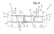
- the snap hinge 10 for furniture comprises a first articulated quadrilateral 11 and a second articulated quadrilateral 12 that have in common amongst themselves a first lever 13 and a second lever 14 and have as a base element, respectively, a first fixing bracket 15, for fixing, for example, to a wall element 16 of a piece of furniture and a second fixing bracket 17 for fixing to a closing element 18 of the piece furniture.
- the invention can be applied electively, if not exclusively, in the sectors of furniture for campers, caravans or the like.
- the wall element 16 constitutes the upper part of the cabinet, the first fixing bracket 15 being anchored on the internal surface of this wall.
- the closing element 18 is substantially a door and the fixing bracket 17 is arranged for being fixed by screws to the surface facing inside the cabinet when the door is in the closed position.
- the first articulated quadrilateral 11 comprises, in articulation sequence, the first fixing bracket 15, a first portion 13' of the first lever 13, a first portion 14' of the second lever 14 and a first arm 19 that are articulated amongst themselves.
- the second articulated quadrilateral 12 comprises, in an articulation sequence, the second fixing bracket 17, the second lever 14, a second portion 13" of the first lever 13 and a second arm 20 that are articulated amongst themselves.
- the elements are preferably produced by moulding from a web.
- levers and the arms constituting the articulated quadrilaterals are made so as to have "U"-shaped profiles with two sides joined by a back bridge, in this manner a double parallel articulation is achieved that makes the hinge more resistant.
- the two fixing brackets 15 and 17 are quadrangular in shape, having a base portion, respectively 15' and 17' intended to be fixed to the furniture from which a pair of parallel flaps rises, respectively first flaps 36 from the first bracket 15 and second flaps 37 from the second bracket 17 that constitute a side of the corresponding articulated quadrilateral.
- first pin 31 On the first pair of flaps 36 there is hinged by means of a first pin 31 an end of the first portion 13' of the first lever 13 that is also made with a profile that is partially U-shaped, being provided with two sides 38 joined by a back bridge 30 that extends along the entire first portion 13'.
- a second pin 40 traverses in a median position said first lever 13 between the first and the second portion 13' and 13'' to hinge the end of the first portion 14' of the second lever 14.
- a third pin 44 is arranged at the end of the first portion 14' of the second lever 14 to hinge on the latter an end of the first arm 19.
- the first quadrilateral 11 is closed with the opposite end of the first arm 19 hinged via a fourth pin 32 spaced away from the first pin 31, on the flaps 36.
- the second quadrilateral is made, starting from the hinging by means of a fifth pin 43, of the second lever 14 on the second flaps 37 of the second bracket 17 that constitute the first side of the second quadrilateral.
- the second lever 14 is completely exploited as a second side of the second quadrilateral until it is connected to the first lever 13, hinging in the second pin 40.
- a third side of the quadrilateral consists of the second portion 13'' of the first lever 13 that at the end is hinged on the second arm 20 by means of a sixth pin 39.
- the second arm 20 is in turn provided with a back bridge 35 that joins the sides.
- the last side of the second quadrilateral consists of the second arm 20 that closes on the second flaps 37, hinging by means of a seventh pin 41.
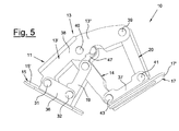
- First and second elastic means 60 and 51 by means of a substantially serial arrangement, cooperate with the two articulated quadrilaterals 11 and 12 to open and support the door and to keep the door closed.
- the first elastic means 60 are arranged in the first quadrilateral between the first pin 31 and a bridge abutment 46 made between the two sides of the first arm 19 near the end thereof hinged on the first flaps 36.
- the second elastic means are engagingly arranged between said sixth pin 39 and an eighth pin 45 inserted into a protrusion 47 exiting the two sides of the second lever 14 between the second and the third pin respectively 40 and 44.
- the second elastic means 51 comprise at least one helicoidal torsion spring 54 compressed along the relevant winding axis.
- the spring 54 is enclosed within a capsule with telescopic caps coupled axially slidably in relation to one another and provided with shaped heads to adapt to the respective anchoring points on the second quadrilateral.
- a first cap 52 is rotatably associated with the sixth pin 39 whilst a second cap 53 is rotatably associated with the eighth pin 45, to perform the elastic action of the second elastic means on the second quadrilateral.
- the first elastic means 60 are made by means of a double spiral flexure spring 61 that is stressed perpendicularly to the winding axis of the double spiral.
- the double spiral is connected centrally by a loop 63 that engages on the first pin 31.
- the ends 64 of the spring are on the other hand engaged on the bridge abutment 46 made between the two sides of the first arm 19.
Landscapes
- Engineering & Computer Science (AREA)
- Mechanical Engineering (AREA)
- Hinges (AREA)
- Closing And Opening Devices For Wings, And Checks For Wings (AREA)
Applications Claiming Priority (1)
| Application Number | Priority Date | Filing Date | Title |
|---|---|---|---|
| IT002213A ITMI20072213A1 (it) | 2007-11-22 | 2007-11-22 | Cerniera a scatto per mobili |
Publications (2)
| Publication Number | Publication Date |
|---|---|
| EP2063055A2 true EP2063055A2 (fr) | 2009-05-27 |
| EP2063055A3 EP2063055A3 (fr) | 2013-05-15 |
Family
ID=40280796
Family Applications (1)
| Application Number | Title | Priority Date | Filing Date |
|---|---|---|---|
| EP08169681.7A Withdrawn EP2063055A3 (fr) | 2007-11-22 | 2008-11-21 | Charnière à encliquetage pour meubles |
Country Status (4)
| Country | Link |
|---|---|
| US (1) | US8132294B2 (fr) |
| EP (1) | EP2063055A3 (fr) |
| AU (1) | AU2008249137A1 (fr) |
| IT (1) | ITMI20072213A1 (fr) |
Families Citing this family (6)
| Publication number | Priority date | Publication date | Assignee | Title |
|---|---|---|---|---|
| PL2909406T3 (pl) * | 2012-10-15 | 2018-12-31 | D.G.N. S.R.L. | Zawias zatrzaskowy z amortyzowanym zamykaniem |
| AU2015202678B2 (en) * | 2014-05-23 | 2019-08-22 | D.G.N. S.R.L. | Snap hinge with damped closing |
| EP3741943A1 (fr) * | 2019-05-23 | 2020-11-25 | D.G.N. S.R.L. | Charnière à fermeture amortie |
| CN111719989A (zh) * | 2020-06-10 | 2020-09-29 | 蒋炉军 | 一种摆叶式幕墙智能开窗机构 |
| CN115680406B (zh) * | 2022-11-04 | 2023-06-13 | 广州珠江装修工程有限公司 | 一种便于安装的超厚重型门门铰链 |
| IT202300021135A1 (it) * | 2023-10-11 | 2025-04-11 | Danco S P A | Cerniera per ante a 45 gradi |
Citations (1)
| Publication number | Priority date | Publication date | Assignee | Title |
|---|---|---|---|---|
| EP1741860A1 (fr) | 2005-07-07 | 2007-01-10 | Daniele Zetti | Charnière à encliquetage pour supporter un élément de fermeture |
Family Cites Families (10)
| Publication number | Priority date | Publication date | Assignee | Title |
|---|---|---|---|---|
| GB673279A (en) * | 1949-07-30 | 1952-06-04 | Briggs Mfg Co | Improvements in or relating to hinge devices |
| US3840936A (en) * | 1972-09-25 | 1974-10-15 | Yutaka Tanaka | Hinge |
| DE29709806U1 (de) * | 1997-04-30 | 1997-07-31 | Arturo Salice S.P.A., Novedrate, Como | Weitwinkelscharnier |
| IT1304909B1 (it) * | 1998-10-13 | 2001-04-05 | Tgn S P A | Cerniera a scatto per il sostegno di elementi piastriformi dichiusura. |
| IT250650Y1 (it) * | 2000-03-31 | 2003-09-24 | T G N Spa | Cerniera a scatto perfezionata per il sostegno di elementipiastriformi di chiusura. |
| EP1231346B1 (fr) * | 2001-02-13 | 2012-02-01 | Liebherr-Hausgeräte Ochsenhausen GmbH | Articulation à charnière |
| JP4021184B2 (ja) * | 2001-12-06 | 2007-12-12 | スガツネ工業株式会社 | キャッチ付きヒンジ |
| DE20212022U1 (de) * | 2002-08-05 | 2002-09-26 | Arturo Salice S.P.A., Novedrate, Como | Scharnier |
| ITMO20030070A1 (it) * | 2003-03-14 | 2004-09-15 | Arrigo Zetti | Cerniera a scatto perfezionata per elementi di chiusura di vani e simili. |
| US20080034540A1 (en) * | 2006-08-11 | 2008-02-14 | Hal Avery | Hinge System |
-
2007
- 2007-11-22 IT IT002213A patent/ITMI20072213A1/it unknown
-
2008
- 2008-11-20 US US12/274,640 patent/US8132294B2/en not_active Expired - Fee Related
- 2008-11-21 EP EP08169681.7A patent/EP2063055A3/fr not_active Withdrawn
- 2008-11-21 AU AU2008249137A patent/AU2008249137A1/en not_active Abandoned
Patent Citations (1)
| Publication number | Priority date | Publication date | Assignee | Title |
|---|---|---|---|---|
| EP1741860A1 (fr) | 2005-07-07 | 2007-01-10 | Daniele Zetti | Charnière à encliquetage pour supporter un élément de fermeture |
Also Published As
| Publication number | Publication date |
|---|---|
| EP2063055A3 (fr) | 2013-05-15 |
| US20090133218A1 (en) | 2009-05-28 |
| US8132294B2 (en) | 2012-03-13 |
| ITMI20072213A1 (it) | 2009-05-23 |
| AU2008249137A1 (en) | 2009-06-11 |
Similar Documents
| Publication | Publication Date | Title |
|---|---|---|
| US8132294B2 (en) | Snap hinge for furniture | |
| EP2947246B1 (fr) | Charnière à déclic avec fermeture amortie | |
| EP1959077B1 (fr) | Dispositif d'ouverture/fermeture pour trappe double d'un meuble | |
| US5291634A (en) | A hinge for the constraining of hatches or doors from a support structure | |
| EP4293186A2 (fr) | Charnière à encliquetage avec fermeture amortie et angle d'ouverture de plus de 90 degrés | |
| EP0994229A2 (fr) | Charnière à effet déclic pour supporter des panneaux de portes | |
| WO2005040956A3 (fr) | Ensemble charniere permettant de connecter de maniere articulee un panneau d'ouverture vertical a un element de meuble | |
| CN111058709B (zh) | 一种家具铰链的集成优化阻尼结构 | |
| CN221346656U (zh) | 用于屋顶窗的铰接件和屋顶窗 | |
| JP2008517227A (ja) | ダンパー装置 | |
| US8283611B2 (en) | Door hinge for a household appliance | |
| KR102431327B1 (ko) | 멀티링크 힌지 | |
| EP2166185B1 (fr) | Charnière à déclic articulée | |
| EP1302150B1 (fr) | Charnière avec dispositif pour contrebalancer et freiner une porte | |
| EP2085548A1 (fr) | Une charnière pour portes ou fenêtres | |
| EP1612356B1 (fr) | Dispositif de charnière pour fenêtres et portes | |
| EP2589736A1 (fr) | Dispositif amortisseur pour charnières de meubles, en particulier pour charnières à déclic, et charnière de meuble, en particulier charnière à déclic, munie d'un tel dispositif amortisseur | |
| CN110952853B (zh) | 一种大角度开合自锁铰链 | |
| EP2615234A1 (fr) | Charnière avec mouvement d'ouverture et de fermeture avec effet de ressort | |
| CN118895910A (zh) | 压缩储能式下悬外倒窗铰链机构及下悬外倒窗 | |
| EP3868991B1 (fr) | Appareil domestique | |
| GB2228766A (en) | Friction stay-hinge | |
| CN2406027Y (zh) | 家具用铰链 | |
| CN201771308U (zh) | 家用电器的门铰链 | |
| CN113107293B (zh) | 一种埋入式铰链的稳固装配结构 |
Legal Events
| Date | Code | Title | Description |
|---|---|---|---|
| PUAI | Public reference made under article 153(3) epc to a published international application that has entered the european phase |
Free format text: ORIGINAL CODE: 0009012 |
|
| AK | Designated contracting states |
Kind code of ref document: A2 Designated state(s): AT BE BG CH CY CZ DE DK EE ES FI FR GB GR HR HU IE IS IT LI LT LU LV MC MT NL NO PL PT RO SE SI SK TR |
|
| AX | Request for extension of the european patent |
Extension state: AL BA MK RS |
|
| PUAL | Search report despatched |
Free format text: ORIGINAL CODE: 0009013 |
|
| AK | Designated contracting states |
Kind code of ref document: A3 Designated state(s): AT BE BG CH CY CZ DE DK EE ES FI FR GB GR HR HU IE IS IT LI LT LU LV MC MT NL NO PL PT RO SE SI SK TR |
|
| AX | Request for extension of the european patent |
Extension state: AL BA MK RS |
|
| RIC1 | Information provided on ipc code assigned before grant |
Ipc: E05F 1/12 20060101ALI20130409BHEP Ipc: E05D 3/16 20060101AFI20130409BHEP Ipc: E05D 11/10 20060101ALI20130409BHEP |
|
| 17P | Request for examination filed |
Effective date: 20131107 |
|
| RBV | Designated contracting states (corrected) |
Designated state(s): AT BE BG CH CY CZ DE DK EE ES FI FR GB GR HR HU IE IS IT LI LT LU LV MC MT NL NO PL PT RO SE SI SK TR |
|
| AKX | Designation fees paid |
Designated state(s): AT BE BG CH CY CZ DE DK EE ES FI FR GB GR HR HU IE IS IT LI LT LU LV MC MT NL NO PL PT RO SE SI SK TR |
|
| GRAP | Despatch of communication of intention to grant a patent |
Free format text: ORIGINAL CODE: EPIDOSNIGR1 |
|
| INTG | Intention to grant announced |
Effective date: 20140714 |
|
| STAA | Information on the status of an ep patent application or granted ep patent |
Free format text: STATUS: THE APPLICATION IS DEEMED TO BE WITHDRAWN |
|
| 18D | Application deemed to be withdrawn |
Effective date: 20141125 |