EP2063063B1 - Couverture rétractable pour ouverture architecturale - Google Patents
Couverture rétractable pour ouverture architecturale Download PDFInfo
- Publication number
- EP2063063B1 EP2063063B1 EP08253603.8A EP08253603A EP2063063B1 EP 2063063 B1 EP2063063 B1 EP 2063063B1 EP 08253603 A EP08253603 A EP 08253603A EP 2063063 B1 EP2063063 B1 EP 2063063B1
- Authority
- EP
- European Patent Office
- Prior art keywords
- flexible element
- retraction mechanism
- plane
- covering device
- primary
- Prior art date
- Legal status (The legal status is an assumption and is not a legal conclusion. Google has not performed a legal analysis and makes no representation as to the accuracy of the status listed.)
- Active
Links
Images


Classifications
-
- E—FIXED CONSTRUCTIONS
- E06—DOORS, WINDOWS, SHUTTERS, OR ROLLER BLINDS IN GENERAL; LADDERS
- E06B—FIXED OR MOVABLE CLOSURES FOR OPENINGS IN BUILDINGS, VEHICLES, FENCES OR LIKE ENCLOSURES IN GENERAL, e.g. DOORS, WINDOWS, BLINDS, GATES
- E06B9/00—Screening or protective devices for wall or similar openings, with or without operating or securing mechanisms; Closures of similar construction
- E06B9/24—Screens or other constructions affording protection against light, especially against sunshine; Similar screens for privacy or appearance; Slat blinds
- E06B9/26—Lamellar or like blinds, e.g. venetian blinds
- E06B9/28—Lamellar or like blinds, e.g. venetian blinds with horizontal lamellae, e.g. non-liftable
- E06B9/30—Lamellar or like blinds, e.g. venetian blinds with horizontal lamellae, e.g. non-liftable liftable
- E06B9/32—Operating, guiding, or securing devices therefor
- E06B9/322—Details of operating devices, e.g. pulleys, brakes, spring drums, drives
-
- E—FIXED CONSTRUCTIONS
- E06—DOORS, WINDOWS, SHUTTERS, OR ROLLER BLINDS IN GENERAL; LADDERS
- E06B—FIXED OR MOVABLE CLOSURES FOR OPENINGS IN BUILDINGS, VEHICLES, FENCES OR LIKE ENCLOSURES IN GENERAL, e.g. DOORS, WINDOWS, BLINDS, GATES
- E06B9/00—Screening or protective devices for wall or similar openings, with or without operating or securing mechanisms; Closures of similar construction
- E06B9/24—Screens or other constructions affording protection against light, especially against sunshine; Similar screens for privacy or appearance; Slat blinds
- E06B9/26—Lamellar or like blinds, e.g. venetian blinds
- E06B9/28—Lamellar or like blinds, e.g. venetian blinds with horizontal lamellae, e.g. non-liftable
- E06B9/30—Lamellar or like blinds, e.g. venetian blinds with horizontal lamellae, e.g. non-liftable liftable
- E06B9/303—Lamellar or like blinds, e.g. venetian blinds with horizontal lamellae, e.g. non-liftable liftable with ladder-tape
- E06B9/308—Lamellar or like blinds, e.g. venetian blinds with horizontal lamellae, e.g. non-liftable liftable with ladder-tape with coaxial tilting bar and raising shaft
-
- E—FIXED CONSTRUCTIONS
- E06—DOORS, WINDOWS, SHUTTERS, OR ROLLER BLINDS IN GENERAL; LADDERS
- E06B—FIXED OR MOVABLE CLOSURES FOR OPENINGS IN BUILDINGS, VEHICLES, FENCES OR LIKE ENCLOSURES IN GENERAL, e.g. DOORS, WINDOWS, BLINDS, GATES
- E06B9/00—Screening or protective devices for wall or similar openings, with or without operating or securing mechanisms; Closures of similar construction
- E06B9/24—Screens or other constructions affording protection against light, especially against sunshine; Similar screens for privacy or appearance; Slat blinds
- E06B9/26—Lamellar or like blinds, e.g. venetian blinds
- E06B9/38—Other details
- E06B9/388—Details of bottom or upper slats or their attachment
-
- E—FIXED CONSTRUCTIONS
- E06—DOORS, WINDOWS, SHUTTERS, OR ROLLER BLINDS IN GENERAL; LADDERS
- E06B—FIXED OR MOVABLE CLOSURES FOR OPENINGS IN BUILDINGS, VEHICLES, FENCES OR LIKE ENCLOSURES IN GENERAL, e.g. DOORS, WINDOWS, BLINDS, GATES
- E06B9/00—Screening or protective devices for wall or similar openings, with or without operating or securing mechanisms; Closures of similar construction
- E06B9/24—Screens or other constructions affording protection against light, especially against sunshine; Similar screens for privacy or appearance; Slat blinds
- E06B9/26—Lamellar or like blinds, e.g. venetian blinds
- E06B9/28—Lamellar or like blinds, e.g. venetian blinds with horizontal lamellae, e.g. non-liftable
- E06B9/30—Lamellar or like blinds, e.g. venetian blinds with horizontal lamellae, e.g. non-liftable liftable
- E06B9/32—Operating, guiding, or securing devices therefor
- E06B9/327—Guides for raisable lamellar blinds with horizontal lamellae
Definitions
- the present invention relates to a retractable covering for architectural openings, having primary and secondary retraction mechanisms.
- the invention provides a retractable covering device as defined in appended claim 1.
- the arrangement of sharing one and the same flexible element between two independent retraction mechanism solves one of the major inconveniences of the prior art.
- the retractable covering device according to the invention includes further features as defined in dependent claims 2 to 11.
- One advantageous embodiment of the retractable covering device further comprises a head rail on a second edge of the covering member opposite the bottom rail, and wherein both the first and secondary retraction mechanisms are associated with the head rail.
- the bottom rail is provided with at least one guide element and wherein the at least one flexible element is looped around the at least one guide element to define a first branch extending from the head rail to the at least one guide element and a second branch extending from the at least one guide element to the head rail and parallel to the first branch of the at least one flexible element.
- the primary retraction mechanism has a first axis of rotation and the secondary retraction mechanism has a second axis of rotation and the second axis of rotation therein is parallel to the first axis of rotation.
- a first plane is defined that is common to the first and second axes of rotation, which first plane is perpendicular to a second plane that is common to the head and bottom rails in an extended position of the collapsible covering member.
- the at least one flexible element extends in a third plane that intersects the first plane common to the first and second axes of rotation substantially between the first and second axes of rotation.
- the third plane is co-extensive with the second plane and wherein the at least one flexible element is deflected from the primary retraction mechanism towards the second plane by a first guide means and from the secondary retraction mechanism towards the second plane by a second guide means.
- the first guide means is a deflection pin and wherein the second guide means is a guiding roller.
- the retractable covering device includes a spring motor.
- This type of drive can be pretensioned to provide for a rapid operation in case of an emergency.
- FIG 1 the reference numerals 1A and 1B generally indicate two slightly different versions of a Venetian blind incorporating the invention.
- the left hand portion ( Figure 1 [A] ) illustrates a Venetian blind 1A, that includes a head rail 3, a collapsible covering member comprising a plurality of slats 5 and a bottom rail 7.
- the slats 5 are each supported by a flexible ladder support 9 as is conventional with Venetian blinds.
- the slats 5 of the blind 1A are each guided and retained in vertical alignment by a side guiding arrangement using a rod or tensioned cable 11 extending through apertures 13 at the longitudinal ends of the slats 5.
- the right hand portion ( Figure 1 [B] ) represents a portion or a Venetian blind 1B, having a head rail 3, slats 5 and a bottom rail 7.
- the slats 5 are each supported by a flexible ladder support 9 and as such the right hand section of version [B] would be similar to a right-hand portion of the left-hand section of version [A].
- version [B] has a channel shaped side guide rail 15 in which slat guiding pins (not shown, but conventional) ride along the guide rail 15.
- Such guiding pins may be attached in the apertures 13 and extend from the longitudinal end of a relevant slat 5.
- the blind 1A, 1B has openings 17 in the slats 5 for the passage of flexible elements 19 for raising the bottom rail 7 and collapsing the slats 5 and ladder supports 9 against the head rail 3 to retract the Venetian blind 1A, 1B.
- the bottom rail 7 is further provided with guide elements 21, which are associated with each support ladder 9 for a purpose to be described herein below.
- a primary retraction mechanism 23 and a secondary retraction mechanism 25 Associated with the head rail 3 is a primary retraction mechanism 23 and a secondary retraction mechanism 25.
- the primary retraction mechanism 23 is preferably a conventional motorized mechanism for raising and lowering a window covering that is controlled by a conventional electric switch or remote control unit (not shoiwn).
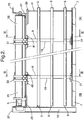
- FIG 2 a rear elevation of the blind of Figure 1 , the same components are referenced by the same reference numerals.
- the longitudinal ends of the head rail 3 are connected with a respective first end bracket 27 and second end bracket 29.
- the first and second end brackets 27, 29 are fixedly attached to the respective longitudinal ends of the head rail 3 and each are adapted to carry one end of the secondary retraction mechanism 25, which is in the form of a spring motor roller having mounted thereon a first an a second rotatable secondary winding reel 31,33.
- the elongated spring roller motor of the secondary retraction mechanism 25 is arranged in parallel relationship with the head rail 3.
- the first and second end brackets 27, 29 are each provided with a relevant first and second mounting flange 35, 37.
- first and second pair of arms 41 are attached to the head rail 3 .
- the first and second pair of arms each form a cradle for rotatably supporting a relevant first and second guiding rollers 45, 47 and first and second deflection pins 49, 51 (see Figures 3 and 4 ) for a purpose to be described.
- FIG 3 is a cross-section taken along the line III-III in Figure 2 .
- the flexible lift element 19 has a first branch 19A extending downwardly from the primary retraction mechanism 23, over the deflection pin 51 (or the similar deflection pin 49 as the case may be), towards a return roller 53 in the guide element 21.
- the primary retraction mechanism 23 is provided with a rotatable primary winding reel 55 onto, or from, which a first end of the flexible element 19 can be wound or unwound as desired.
- a second branch 19B of the flexible element 19 extends upwardly to the second guide roller 47 (or the first guide roller 45 as the case may be) to have its second end wound by the second secondary winding reel 33 (or first secondary winding reel 31 as the case may be).
- FIG. 3 and 4 denotes an exemplary guiding pin for use with a side guiding rail (reference “15" as indicated in Figures 1 and 2 ).
- Figure 4 which is a cross-section along the lines IV-IV of Figure 2 , shows in more detail one of the ladder supports 9.
- Each ladder support 9 has a first branch 9A and a second branch 9B which both extend from a tilt mechanism associated with the primary retraction mechanism 23.
- This tilt mechanism is not shown, but is conventional for combined mono-commando type tilting and lifting mechanisms with which the skilled person is familiar. In the present context a detailed description of such devices is thus deemed redundant.
- the first branch 9A of the ladder support 9 is deflected towards a plane in which the flexible element 19 extends downwardly towards the guide element 21 on the bottom rail 7.
- the first branch 9A is connected to a second branch 9B which extends upwardly from the guide element 21 along opposite edges of slats 5, back to the tilting mechanism associated with the primary retraction mechanism 23.
- the interconnected first and second branches enable the ladder support 9 to extend through a funnel through the guide element 21 and to effect tilting of the slats without altering the position of the bottom rail 7.
- the first and second branches 9A, 9B are each connected with opposite ones of the longitudinal edges of slats 5 at points 59A and 59B. This interconnection can be accomplished by any suitable conventional means as known to the skilled person. It is also possible to support the slats 5 between cross-rungs, extending between points 59A and 59B of the first and second branches of the ladder support 9. Also this system is well known to the skilled person and will not require any further explanation.
- Each of the primary and secondary retraction mechanisms 23, 25 are adapted to raise the bottom rail 7 by winding a relevant first or second end of the flexible element 19.
- the primary retraction mechanism 23 lifts the bottom rail, it will be lifted with half the speed at which the first branch 19A of the flexible element is wound. This will basically reduce the force required to raise a relatively heavy blind, which may be an advantage to the general applicability of the primary retraction mechanism 23.
- the further advantage obtained is that there will be no flexible lift element of the secondary retraction mechanism that is compromised or distorted by the lifting action of the primary retraction mechanism.
- the secondary retraction mechanism 25 may lift the bottom rail 7 through winding of the second branch 19B of the flexible element 19 in case of an emergency. Again this action will not compromise or interfere with the operation of the primary retraction mechanism 23.
- the secondary retraction mechanism 25 may be provided with a very strong spring motor which may actually accelerate the movement of bottom rail 7 towards the head rail 3. Thereby the flexible covering member formed by the slats 5 and the ladder supports 9 is collapsed between the bottom rail 7 and the head rail 3.
- the head rail 3 can be provided with an operation device 61 (see Figure 1 ) that is adapted to withdraw a latch 63 from a circumferential cavity 65 provided in a collar 67 of the secondary retraction mechanism 25 ( Figures 1 and 4 ).
- the operation device 61 can be remotely controlled by a fire alarm or may be a mechanical device that is responsive to temperature or smoke conditions that can be associated with a fire in a building. Also the operation device can be manually controlled from a button or handle in the close proximity of the escape opening with which the blind is associated. The skilled person will generally be familiar with other suitable mechanisms for withdrawal of the latch 63 that are both effective and compliant with the applicable regulations.
Landscapes
- Engineering & Computer Science (AREA)
- Structural Engineering (AREA)
- Architecture (AREA)
- Civil Engineering (AREA)
- Operating, Guiding And Securing Of Roll- Type Closing Members (AREA)
- Blinds (AREA)
Claims (11)
- Dispositif de revêtement rétractable pour ouvertures architecturales, incluant :un élément de revêtement pliable,une barre inférieure (7), positionnée le long d'un premier bord de l'élément de revêtement pliable ;au moins un élément flexible (19) en engagement avec la barre inférieure (7) pour élever la barre inférieure (7) et replier l'élément de revêtement pour définir une position rétractée du revêtement ;un mécanisme de rétraction primaire (23) pour rétracter l'au moins un élément flexible (19) d'une première extrémité de l'au moins un élément flexible (19) ; etun mécanisme de rétraction secondaire (25) connecté fonctionnellement à la barre inférieure (7) ;dans lequel le mécanisme de rétraction principal (23) comprend au moins une bobine d'enroulement primaire rotative (55) à laquelle une première extrémité de l'au moins un élément flexible (19) est fixée, la première extrémité de l'élément flexible (19) étant enroulée ou déroulé sur ou à partir de l'au moins une bobine d'enroulement primaire rotative ;dans lequel le mécanisme de rétraction secondaire (25) comprend au moins une bobine d'enroulement secondaire rotative (33) ;par lequel le mécanisme de rétraction principal (23) est configuré pour rétracter l'élément de revêtement lors de la rétraction de l'au moins un élément flexible (19) de la première extrémité de l'au moins un élément flexible (19) ;et par lequel le mécanisme de rétraction principal (23) est indépendant du mécanisme de rétraction secondaire (25) ;caractérisé en ce que le mécanisme de rétraction secondaire (25) est agencé pour rétracter l'au moins un élément flexible (19) d'une seconde extrémité de l'au moins un élément flexible (19) ;en ce que la seconde extrémité de l'au moins un élément flexible (19) est fixée à l'au moins une bobine d'enroulement secondaire rotative (33) ; et en ce quele mécanisme de rétraction secondaire (25) est configuré pour rétracter sélectivement également l'élément de revêtement lors de la rétraction de l'au moins un élément flexible (19) de la seconde extrémité de l'au moins un élément flexible (19).
- Dispositif de revêtement rétractable selon la revendication 1, dans lequel l'élément de couverture pliable comprend une pluralité de lattes allongées (5), maintenues dans un arrangement mutuellement parallèle et espacé par au moins deux échelles de suspension flexibles (9), qui sont espacées l'une de l'autre le long des lattes (5).
- Dispositif de revêtement rétractable selon la revendication 1 ou 2, comprenant en outre un rail de tête (3) sur un second bord de l'élément de revêtement opposé au rail inférieur (7), et dans lequel les premier et second mécanismes de rétraction (23, 25) sont associés au rail de tête (3).
- Dispositif de revêtement rétractable selon la revendication 3, dans lequel le rail inférieur (7) est pourvu d'au moins un élément de guidage (21) et dans lequel l'au moins un élément flexible (19) est bouclé autour de l'au moins un élément de guidage (21) pour définir une première branche (19A) s'étendant du rail de tête (3) à l'au moins un élément de guidage (21) et une seconde branche (19B) s'étendant de l'au moins un élément de guidage (21) au rail de tête (3) et parallèle à la première branche (19A) de l'au moins un élément flexible (19).
- Dispositif de revêtement rétractable selon l'une des revendications 1 à 4, dans lequel le mécanisme de rétraction secondaire (25) comprend un moteur à ressort.
- Dispositif de revêtement rétractable selon l'une des revendications 1 à 5, dans lequel l'au moins un élément flexible (19) est un ruban de levage et la rétraction de l'élément de couverture peut être effectuée en soulevant le rail inférieur (7).
- Dispositif de revêtement rétractable selon l'une des revendications 1 à 6, dans lequel le mécanisme de rétraction primaire (23) a un premier axe de rotation et le mécanisme de rétraction secondaire (25) a un second axe de rotation et dans lequel le second axe de rotation est parallèle au premier axe de rotation.
- Dispositif de revêtement rétractable selon la revendication 7, dans lequel un premier plan est défini qui est commun aux premier et second axes de rotation, lequel premier plan est perpendiculaire à un deuxième plan qui est commun aux rails de tête (3) et de fond (7) dans une position déployée de l'élément de revêtement pliable.
- Dispositif de revêtement rétractable selon la revendication 8, dans lequel l'au moins un élément flexible (19) s'étend dans un troisième plan qui coupe le premier plan commun aux premier et second axes de rotation sensiblement entre les premier et second axes de rotation.
- Dispositif de revêtement rétractable selon la revendication 9, dans lequel le troisième plan est coextensif avec le second plan et dans lequel l'au moins un élément flexible (19) est dévié du mécanisme de rétraction primaire (23) vers le second plan par un premier moyen de guidage et du mécanisme de rétraction secondaire (25) vers le second plan par un second moyen de guidage.
- Dispositif de revêtement rétractable selon la revendication 10, dans lequel le premier moyen de guidage est une broche de déviation (49, 51) et dans lequel le second moyen de guidage est un rouleau de guidage (45, 47).
Priority Applications (1)
| Application Number | Priority Date | Filing Date | Title |
|---|---|---|---|
| EP08253603.8A EP2063063B1 (fr) | 2007-11-21 | 2008-11-05 | Couverture rétractable pour ouverture architecturale |
Applications Claiming Priority (2)
| Application Number | Priority Date | Filing Date | Title |
|---|---|---|---|
| EP07022608 | 2007-11-21 | ||
| EP08253603.8A EP2063063B1 (fr) | 2007-11-21 | 2008-11-05 | Couverture rétractable pour ouverture architecturale |
Publications (3)
| Publication Number | Publication Date |
|---|---|
| EP2063063A2 EP2063063A2 (fr) | 2009-05-27 |
| EP2063063A3 EP2063063A3 (fr) | 2013-09-25 |
| EP2063063B1 true EP2063063B1 (fr) | 2020-02-19 |
Family
ID=40193822
Family Applications (1)
| Application Number | Title | Priority Date | Filing Date |
|---|---|---|---|
| EP08253603.8A Active EP2063063B1 (fr) | 2007-11-21 | 2008-11-05 | Couverture rétractable pour ouverture architecturale |
Country Status (1)
| Country | Link |
|---|---|
| EP (1) | EP2063063B1 (fr) |
Family Cites Families (6)
| Publication number | Priority date | Publication date | Assignee | Title |
|---|---|---|---|---|
| US3279528A (en) * | 1962-03-02 | 1966-10-18 | Thomas F Gambon | Shade |
| DE3238473C2 (de) | 1982-10-16 | 1985-04-18 | Ehage Jalousie-Fabrik Erich Hinnenberg GmbH & Co KG, 4006 Erkrath | Rafflamellen-Jalousie, insbesondere für Fluchttüren |
| DE29505849U1 (de) * | 1995-04-11 | 1995-06-01 | Seitz, Eugen, 71546 Aspach | Antriebseinrichtung für ein Rollo o.dgl. |
| TW576476U (en) * | 2003-03-17 | 2004-02-11 | Nien Made Entpr Co Ltd | Rolling blind with light penetrating cloth curtains on both front and rear sides |
| DE202005000588U1 (de) | 2005-01-14 | 2005-03-24 | Schueco Int Kg | Sonnenschutzanlage mit Notraffvorrichtung |
| DE202006015929U1 (de) * | 2006-10-18 | 2006-12-14 | Guangzhou Carford Decoration Material Co., Ltd. | Jalousie-Bodenleiste mit arbeitssparender Funktion |
-
2008
- 2008-11-05 EP EP08253603.8A patent/EP2063063B1/fr active Active
Non-Patent Citations (1)
| Title |
|---|
| None * |
Also Published As
| Publication number | Publication date |
|---|---|
| EP2063063A2 (fr) | 2009-05-27 |
| EP2063063A3 (fr) | 2013-09-25 |
Similar Documents
| Publication | Publication Date | Title |
|---|---|---|
| US7117919B2 (en) | Cordless blind with lock mechanism | |
| EP2374983B1 (fr) | Store pliable et enroulable | |
| US7063122B2 (en) | Bottom-up/top-down retractable cellular shade | |
| US9670721B2 (en) | Guide arrangement for hangings | |
| US7287570B2 (en) | Window covering lifting system and method | |
| EP2479374B1 (fr) | Couverture de fenêtre | |
| EP0123226A1 (fr) | Système mobile d'ombrage | |
| US9957750B2 (en) | Window covering positional adjustment apparatus | |
| US20130248125A1 (en) | Window Covering Having a Lift System Utilizing Conical Spools | |
| CA3086296C (fr) | Ensemble chaine semi-rigide | |
| WO2013074130A1 (fr) | Système et procédé pour store automatique libérable à ouverture vers le bas | |
| CN104411910B (zh) | 具有两个百叶窗上轨的百叶窗 | |
| EP3409875B1 (fr) | Store vénitien avec un mécanisme de commande de réglage d'inclinaison | |
| US20160069130A1 (en) | Cordless blind system and retro-fit method | |
| EP2063063B1 (fr) | Couverture rétractable pour ouverture architecturale | |
| KR101098843B1 (ko) | 블라인드 장치 | |
| CA2814575C (fr) | Ensemble store | |
| US20060137830A1 (en) | Winding mechanism of blind | |
| EP0892144B1 (fr) | Store ou jalousie pour fenêtre | |
| EP0513468A1 (fr) | Dispositif de couverture de fenêtres | |
| KR102868239B1 (ko) | 수평식 창문 블라인드 | |
| US1266290A (en) | Shade-roller. | |
| CA3178817A1 (fr) | Dispositif d~exploitation pour un couvre-fenetre | |
| EP1994863A2 (fr) | Une couverture de fenêtre | |
| JPH0328713Y2 (fr) |
Legal Events
| Date | Code | Title | Description |
|---|---|---|---|
| PUAI | Public reference made under article 153(3) epc to a published international application that has entered the european phase |
Free format text: ORIGINAL CODE: 0009012 |
|
| AK | Designated contracting states |
Kind code of ref document: A2 Designated state(s): AT BE BG CH CY CZ DE DK EE ES FI FR GB GR HR HU IE IS IT LI LT LU LV MC MT NL NO PL PT RO SE SI SK TR |
|
| AX | Request for extension of the european patent |
Extension state: AL BA MK RS |
|
| PUAL | Search report despatched |
Free format text: ORIGINAL CODE: 0009013 |
|
| AK | Designated contracting states |
Kind code of ref document: A3 Designated state(s): AT BE BG CH CY CZ DE DK EE ES FI FR GB GR HR HU IE IS IT LI LT LU LV MC MT NL NO PL PT RO SE SI SK TR |
|
| AX | Request for extension of the european patent |
Extension state: AL BA MK RS |
|
| RIC1 | Information provided on ipc code assigned before grant |
Ipc: E06B 9/388 20060101ALI20130816BHEP Ipc: E06B 9/322 20060101ALI20130816BHEP Ipc: E06B 9/32 20060101AFI20130816BHEP Ipc: E06B 9/327 20060101ALI20130816BHEP Ipc: E06B 9/308 20060101ALI20130816BHEP |
|
| 17P | Request for examination filed |
Effective date: 20140324 |
|
| RBV | Designated contracting states (corrected) |
Designated state(s): AT BE BG CH CY CZ DE DK EE ES FI FR GB GR HR HU IE IS IT LI LT LU LV MC MT NL NO PL PT RO SE SI SK TR |
|
| AKX | Designation fees paid |
Designated state(s): AT BE BG CH CY CZ DE DK EE ES FI FR GB GR HR HU IE IS IT LI LT LU LV MC MT NL NO PL PT RO SE SI SK TR |
|
| 17Q | First examination report despatched |
Effective date: 20160902 |
|
| STAA | Information on the status of an ep patent application or granted ep patent |
Free format text: STATUS: EXAMINATION IS IN PROGRESS |
|
| GRAP | Despatch of communication of intention to grant a patent |
Free format text: ORIGINAL CODE: EPIDOSNIGR1 |
|
| STAA | Information on the status of an ep patent application or granted ep patent |
Free format text: STATUS: GRANT OF PATENT IS INTENDED |
|
| INTG | Intention to grant announced |
Effective date: 20191017 |
|
| GRAS | Grant fee paid |
Free format text: ORIGINAL CODE: EPIDOSNIGR3 |
|
| GRAA | (expected) grant |
Free format text: ORIGINAL CODE: 0009210 |
|
| STAA | Information on the status of an ep patent application or granted ep patent |
Free format text: STATUS: THE PATENT HAS BEEN GRANTED |
|
| AK | Designated contracting states |
Kind code of ref document: B1 Designated state(s): AT BE BG CH CY CZ DE DK EE ES FI FR GB GR HR HU IE IS IT LI LT LU LV MC MT NL NO PL PT RO SE SI SK TR |
|
| REG | Reference to a national code |
Ref country code: GB Ref legal event code: FG4D |
|
| REG | Reference to a national code |
Ref country code: CH Ref legal event code: EP |
|
| REG | Reference to a national code |
Ref country code: DE Ref legal event code: R096 Ref document number: 602008062151 Country of ref document: DE |
|
| REG | Reference to a national code |
Ref country code: AT Ref legal event code: REF Ref document number: 1235156 Country of ref document: AT Kind code of ref document: T Effective date: 20200315 |
|
| REG | Reference to a national code |
Ref country code: IE Ref legal event code: FG4D |
|
| REG | Reference to a national code |
Ref country code: NL Ref legal event code: MP Effective date: 20200219 |
|
| PG25 | Lapsed in a contracting state [announced via postgrant information from national office to epo] |
Ref country code: FI Free format text: LAPSE BECAUSE OF FAILURE TO SUBMIT A TRANSLATION OF THE DESCRIPTION OR TO PAY THE FEE WITHIN THE PRESCRIBED TIME-LIMIT Effective date: 20200219 Ref country code: NO Free format text: LAPSE BECAUSE OF FAILURE TO SUBMIT A TRANSLATION OF THE DESCRIPTION OR TO PAY THE FEE WITHIN THE PRESCRIBED TIME-LIMIT Effective date: 20200519 |
|
| REG | Reference to a national code |
Ref country code: LT Ref legal event code: MG4D |
|
| PG25 | Lapsed in a contracting state [announced via postgrant information from national office to epo] |
Ref country code: HR Free format text: LAPSE BECAUSE OF FAILURE TO SUBMIT A TRANSLATION OF THE DESCRIPTION OR TO PAY THE FEE WITHIN THE PRESCRIBED TIME-LIMIT Effective date: 20200219 Ref country code: LV Free format text: LAPSE BECAUSE OF FAILURE TO SUBMIT A TRANSLATION OF THE DESCRIPTION OR TO PAY THE FEE WITHIN THE PRESCRIBED TIME-LIMIT Effective date: 20200219 Ref country code: SE Free format text: LAPSE BECAUSE OF FAILURE TO SUBMIT A TRANSLATION OF THE DESCRIPTION OR TO PAY THE FEE WITHIN THE PRESCRIBED TIME-LIMIT Effective date: 20200219 Ref country code: BG Free format text: LAPSE BECAUSE OF FAILURE TO SUBMIT A TRANSLATION OF THE DESCRIPTION OR TO PAY THE FEE WITHIN THE PRESCRIBED TIME-LIMIT Effective date: 20200519 Ref country code: GR Free format text: LAPSE BECAUSE OF FAILURE TO SUBMIT A TRANSLATION OF THE DESCRIPTION OR TO PAY THE FEE WITHIN THE PRESCRIBED TIME-LIMIT Effective date: 20200520 Ref country code: IS Free format text: LAPSE BECAUSE OF FAILURE TO SUBMIT A TRANSLATION OF THE DESCRIPTION OR TO PAY THE FEE WITHIN THE PRESCRIBED TIME-LIMIT Effective date: 20200619 |
|
| PG25 | Lapsed in a contracting state [announced via postgrant information from national office to epo] |
Ref country code: NL Free format text: LAPSE BECAUSE OF FAILURE TO SUBMIT A TRANSLATION OF THE DESCRIPTION OR TO PAY THE FEE WITHIN THE PRESCRIBED TIME-LIMIT Effective date: 20200219 |
|
| PG25 | Lapsed in a contracting state [announced via postgrant information from national office to epo] |
Ref country code: LT Free format text: LAPSE BECAUSE OF FAILURE TO SUBMIT A TRANSLATION OF THE DESCRIPTION OR TO PAY THE FEE WITHIN THE PRESCRIBED TIME-LIMIT Effective date: 20200219 Ref country code: EE Free format text: LAPSE BECAUSE OF FAILURE TO SUBMIT A TRANSLATION OF THE DESCRIPTION OR TO PAY THE FEE WITHIN THE PRESCRIBED TIME-LIMIT Effective date: 20200219 Ref country code: CZ Free format text: LAPSE BECAUSE OF FAILURE TO SUBMIT A TRANSLATION OF THE DESCRIPTION OR TO PAY THE FEE WITHIN THE PRESCRIBED TIME-LIMIT Effective date: 20200219 Ref country code: RO Free format text: LAPSE BECAUSE OF FAILURE TO SUBMIT A TRANSLATION OF THE DESCRIPTION OR TO PAY THE FEE WITHIN THE PRESCRIBED TIME-LIMIT Effective date: 20200219 Ref country code: SK Free format text: LAPSE BECAUSE OF FAILURE TO SUBMIT A TRANSLATION OF THE DESCRIPTION OR TO PAY THE FEE WITHIN THE PRESCRIBED TIME-LIMIT Effective date: 20200219 Ref country code: PT Free format text: LAPSE BECAUSE OF FAILURE TO SUBMIT A TRANSLATION OF THE DESCRIPTION OR TO PAY THE FEE WITHIN THE PRESCRIBED TIME-LIMIT Effective date: 20200712 Ref country code: ES Free format text: LAPSE BECAUSE OF FAILURE TO SUBMIT A TRANSLATION OF THE DESCRIPTION OR TO PAY THE FEE WITHIN THE PRESCRIBED TIME-LIMIT Effective date: 20200219 Ref country code: DK Free format text: LAPSE BECAUSE OF FAILURE TO SUBMIT A TRANSLATION OF THE DESCRIPTION OR TO PAY THE FEE WITHIN THE PRESCRIBED TIME-LIMIT Effective date: 20200219 |
|
| REG | Reference to a national code |
Ref country code: DE Ref legal event code: R097 Ref document number: 602008062151 Country of ref document: DE |
|
| PLBE | No opposition filed within time limit |
Free format text: ORIGINAL CODE: 0009261 |
|
| STAA | Information on the status of an ep patent application or granted ep patent |
Free format text: STATUS: NO OPPOSITION FILED WITHIN TIME LIMIT |
|
| REG | Reference to a national code |
Ref country code: AT Ref legal event code: UEP Ref document number: 1235156 Country of ref document: AT Kind code of ref document: T Effective date: 20200219 |
|
| 26N | No opposition filed |
Effective date: 20201120 |
|
| PG25 | Lapsed in a contracting state [announced via postgrant information from national office to epo] |
Ref country code: IT Free format text: LAPSE BECAUSE OF FAILURE TO SUBMIT A TRANSLATION OF THE DESCRIPTION OR TO PAY THE FEE WITHIN THE PRESCRIBED TIME-LIMIT Effective date: 20200219 |
|
| PG25 | Lapsed in a contracting state [announced via postgrant information from national office to epo] |
Ref country code: SI Free format text: LAPSE BECAUSE OF FAILURE TO SUBMIT A TRANSLATION OF THE DESCRIPTION OR TO PAY THE FEE WITHIN THE PRESCRIBED TIME-LIMIT Effective date: 20200219 Ref country code: PL Free format text: LAPSE BECAUSE OF FAILURE TO SUBMIT A TRANSLATION OF THE DESCRIPTION OR TO PAY THE FEE WITHIN THE PRESCRIBED TIME-LIMIT Effective date: 20200219 |
|
| PG25 | Lapsed in a contracting state [announced via postgrant information from national office to epo] |
Ref country code: MC Free format text: LAPSE BECAUSE OF FAILURE TO SUBMIT A TRANSLATION OF THE DESCRIPTION OR TO PAY THE FEE WITHIN THE PRESCRIBED TIME-LIMIT Effective date: 20200219 |
|
| REG | Reference to a national code |
Ref country code: CH Ref legal event code: PL |
|
| GBPC | Gb: european patent ceased through non-payment of renewal fee |
Effective date: 20201105 |
|
| PG25 | Lapsed in a contracting state [announced via postgrant information from national office to epo] |
Ref country code: LU Free format text: LAPSE BECAUSE OF NON-PAYMENT OF DUE FEES Effective date: 20201105 |
|
| REG | Reference to a national code |
Ref country code: BE Ref legal event code: MM Effective date: 20201130 |
|
| PG25 | Lapsed in a contracting state [announced via postgrant information from national office to epo] |
Ref country code: CH Free format text: LAPSE BECAUSE OF NON-PAYMENT OF DUE FEES Effective date: 20201130 Ref country code: LI Free format text: LAPSE BECAUSE OF NON-PAYMENT OF DUE FEES Effective date: 20201130 |
|
| PG25 | Lapsed in a contracting state [announced via postgrant information from national office to epo] |
Ref country code: FR Free format text: LAPSE BECAUSE OF NON-PAYMENT OF DUE FEES Effective date: 20201130 Ref country code: IE Free format text: LAPSE BECAUSE OF NON-PAYMENT OF DUE FEES Effective date: 20201105 |
|
| PG25 | Lapsed in a contracting state [announced via postgrant information from national office to epo] |
Ref country code: GB Free format text: LAPSE BECAUSE OF NON-PAYMENT OF DUE FEES Effective date: 20201105 |
|
| PG25 | Lapsed in a contracting state [announced via postgrant information from national office to epo] |
Ref country code: TR Free format text: LAPSE BECAUSE OF FAILURE TO SUBMIT A TRANSLATION OF THE DESCRIPTION OR TO PAY THE FEE WITHIN THE PRESCRIBED TIME-LIMIT Effective date: 20200219 Ref country code: MT Free format text: LAPSE BECAUSE OF FAILURE TO SUBMIT A TRANSLATION OF THE DESCRIPTION OR TO PAY THE FEE WITHIN THE PRESCRIBED TIME-LIMIT Effective date: 20200219 Ref country code: CY Free format text: LAPSE BECAUSE OF FAILURE TO SUBMIT A TRANSLATION OF THE DESCRIPTION OR TO PAY THE FEE WITHIN THE PRESCRIBED TIME-LIMIT Effective date: 20200219 |
|
| PG25 | Lapsed in a contracting state [announced via postgrant information from national office to epo] |
Ref country code: BE Free format text: LAPSE BECAUSE OF NON-PAYMENT OF DUE FEES Effective date: 20201130 |
|
| PGFP | Annual fee paid to national office [announced via postgrant information from national office to epo] |
Ref country code: AT Payment date: 20221025 Year of fee payment: 15 |
|
| P01 | Opt-out of the competence of the unified patent court (upc) registered |
Effective date: 20230331 |
|
| REG | Reference to a national code |
Ref country code: AT Ref legal event code: MM01 Ref document number: 1235156 Country of ref document: AT Kind code of ref document: T Effective date: 20231105 |
|
| PG25 | Lapsed in a contracting state [announced via postgrant information from national office to epo] |
Ref country code: AT Free format text: LAPSE BECAUSE OF NON-PAYMENT OF DUE FEES Effective date: 20231105 |
|
| PG25 | Lapsed in a contracting state [announced via postgrant information from national office to epo] |
Ref country code: AT Free format text: LAPSE BECAUSE OF NON-PAYMENT OF DUE FEES Effective date: 20231105 |
|
| PG25 | Lapsed in a contracting state [announced via postgrant information from national office to epo] |
Ref country code: IS Free format text: LAPSE BECAUSE OF NON-PAYMENT OF DUE FEES Effective date: 20200619 |
|
| PGFP | Annual fee paid to national office [announced via postgrant information from national office to epo] |
Ref country code: DE Payment date: 20251126 Year of fee payment: 18 |