EP2063152A1 - Verfahren zum Schalten eines Doppelkupplungsgetriebes - Google Patents
Verfahren zum Schalten eines Doppelkupplungsgetriebes Download PDFInfo
- Publication number
- EP2063152A1 EP2063152A1 EP08105379A EP08105379A EP2063152A1 EP 2063152 A1 EP2063152 A1 EP 2063152A1 EP 08105379 A EP08105379 A EP 08105379A EP 08105379 A EP08105379 A EP 08105379A EP 2063152 A1 EP2063152 A1 EP 2063152A1
- Authority
- EP
- European Patent Office
- Prior art keywords
- clutch
- engine
- torque
- engine speed
- characteristic
- Prior art date
- Legal status (The legal status is an assumption and is not a legal conclusion. Google has not performed a legal analysis and makes no representation as to the accuracy of the status listed.)
- Granted
Links
Images


Classifications
-
- F—MECHANICAL ENGINEERING; LIGHTING; HEATING; WEAPONS; BLASTING
- F16—ENGINEERING ELEMENTS AND UNITS; GENERAL MEASURES FOR PRODUCING AND MAINTAINING EFFECTIVE FUNCTIONING OF MACHINES OR INSTALLATIONS; THERMAL INSULATION IN GENERAL
- F16D—COUPLINGS FOR TRANSMITTING ROTATION; CLUTCHES; BRAKES
- F16D48/00—External control of clutches
- F16D48/06—Control by electric or electronic means, e.g. of fluid pressure
- F16D48/08—Regulating clutch take-up on starting
-
- F—MECHANICAL ENGINEERING; LIGHTING; HEATING; WEAPONS; BLASTING
- F16—ENGINEERING ELEMENTS AND UNITS; GENERAL MEASURES FOR PRODUCING AND MAINTAINING EFFECTIVE FUNCTIONING OF MACHINES OR INSTALLATIONS; THERMAL INSULATION IN GENERAL
- F16H—GEARING
- F16H61/00—Control functions within control units of change-speed- or reversing-gearings for conveying rotary motion ; Control of exclusively fluid gearing, friction gearing, gearings with endless flexible members or other particular types of gearing
- F16H61/68—Control functions within control units of change-speed- or reversing-gearings for conveying rotary motion ; Control of exclusively fluid gearing, friction gearing, gearings with endless flexible members or other particular types of gearing specially adapted for stepped gearings
- F16H61/684—Control functions within control units of change-speed- or reversing-gearings for conveying rotary motion ; Control of exclusively fluid gearing, friction gearing, gearings with endless flexible members or other particular types of gearing specially adapted for stepped gearings without interruption of drive
- F16H61/688—Control functions within control units of change-speed- or reversing-gearings for conveying rotary motion ; Control of exclusively fluid gearing, friction gearing, gearings with endless flexible members or other particular types of gearing specially adapted for stepped gearings without interruption of drive with two inputs, e.g. selection of one of two torque-flow paths by clutches
-
- F—MECHANICAL ENGINEERING; LIGHTING; HEATING; WEAPONS; BLASTING
- F16—ENGINEERING ELEMENTS AND UNITS; GENERAL MEASURES FOR PRODUCING AND MAINTAINING EFFECTIVE FUNCTIONING OF MACHINES OR INSTALLATIONS; THERMAL INSULATION IN GENERAL
- F16D—COUPLINGS FOR TRANSMITTING ROTATION; CLUTCHES; BRAKES
- F16D2500/00—External control of clutches by electric or electronic means
- F16D2500/10—System to be controlled
- F16D2500/108—Gear
- F16D2500/1086—Concentric shafts
-
- F—MECHANICAL ENGINEERING; LIGHTING; HEATING; WEAPONS; BLASTING
- F16—ENGINEERING ELEMENTS AND UNITS; GENERAL MEASURES FOR PRODUCING AND MAINTAINING EFFECTIVE FUNCTIONING OF MACHINES OR INSTALLATIONS; THERMAL INSULATION IN GENERAL
- F16D—COUPLINGS FOR TRANSMITTING ROTATION; CLUTCHES; BRAKES
- F16D2500/00—External control of clutches by electric or electronic means
- F16D2500/30—Signal inputs
- F16D2500/304—Signal inputs from the clutch
- F16D2500/3042—Signal inputs from the clutch from the output shaft
- F16D2500/30426—Speed of the output shaft
-
- F—MECHANICAL ENGINEERING; LIGHTING; HEATING; WEAPONS; BLASTING
- F16—ENGINEERING ELEMENTS AND UNITS; GENERAL MEASURES FOR PRODUCING AND MAINTAINING EFFECTIVE FUNCTIONING OF MACHINES OR INSTALLATIONS; THERMAL INSULATION IN GENERAL
- F16D—COUPLINGS FOR TRANSMITTING ROTATION; CLUTCHES; BRAKES
- F16D2500/00—External control of clutches by electric or electronic means
- F16D2500/30—Signal inputs
- F16D2500/306—Signal inputs from the engine
- F16D2500/3067—Speed of the engine
-
- F—MECHANICAL ENGINEERING; LIGHTING; HEATING; WEAPONS; BLASTING
- F16—ENGINEERING ELEMENTS AND UNITS; GENERAL MEASURES FOR PRODUCING AND MAINTAINING EFFECTIVE FUNCTIONING OF MACHINES OR INSTALLATIONS; THERMAL INSULATION IN GENERAL
- F16D—COUPLINGS FOR TRANSMITTING ROTATION; CLUTCHES; BRAKES
- F16D2500/00—External control of clutches by electric or electronic means
- F16D2500/30—Signal inputs
- F16D2500/308—Signal inputs from the transmission
- F16D2500/3081—Signal inputs from the transmission from the input shaft
- F16D2500/30816—Speed of the input shaft
-
- F—MECHANICAL ENGINEERING; LIGHTING; HEATING; WEAPONS; BLASTING
- F16—ENGINEERING ELEMENTS AND UNITS; GENERAL MEASURES FOR PRODUCING AND MAINTAINING EFFECTIVE FUNCTIONING OF MACHINES OR INSTALLATIONS; THERMAL INSULATION IN GENERAL
- F16D—COUPLINGS FOR TRANSMITTING ROTATION; CLUTCHES; BRAKES
- F16D2500/00—External control of clutches by electric or electronic means
- F16D2500/30—Signal inputs
- F16D2500/314—Signal inputs from the user
- F16D2500/3146—Signal inputs from the user input from levers
- F16D2500/31466—Gear lever
-
- F—MECHANICAL ENGINEERING; LIGHTING; HEATING; WEAPONS; BLASTING
- F16—ENGINEERING ELEMENTS AND UNITS; GENERAL MEASURES FOR PRODUCING AND MAINTAINING EFFECTIVE FUNCTIONING OF MACHINES OR INSTALLATIONS; THERMAL INSULATION IN GENERAL
- F16D—COUPLINGS FOR TRANSMITTING ROTATION; CLUTCHES; BRAKES
- F16D2500/00—External control of clutches by electric or electronic means
- F16D2500/50—Problem to be solved by the control system
- F16D2500/502—Relating the clutch
- F16D2500/50224—Drive-off
-
- F—MECHANICAL ENGINEERING; LIGHTING; HEATING; WEAPONS; BLASTING
- F16—ENGINEERING ELEMENTS AND UNITS; GENERAL MEASURES FOR PRODUCING AND MAINTAINING EFFECTIVE FUNCTIONING OF MACHINES OR INSTALLATIONS; THERMAL INSULATION IN GENERAL
- F16D—COUPLINGS FOR TRANSMITTING ROTATION; CLUTCHES; BRAKES
- F16D2500/00—External control of clutches by electric or electronic means
- F16D2500/50—Problem to be solved by the control system
- F16D2500/502—Relating the clutch
- F16D2500/50227—Control of clutch to control engine
-
- F—MECHANICAL ENGINEERING; LIGHTING; HEATING; WEAPONS; BLASTING
- F16—ENGINEERING ELEMENTS AND UNITS; GENERAL MEASURES FOR PRODUCING AND MAINTAINING EFFECTIVE FUNCTIONING OF MACHINES OR INSTALLATIONS; THERMAL INSULATION IN GENERAL
- F16D—COUPLINGS FOR TRANSMITTING ROTATION; CLUTCHES; BRAKES
- F16D2500/00—External control of clutches by electric or electronic means
- F16D2500/50—Problem to be solved by the control system
- F16D2500/506—Relating the transmission
- F16D2500/50684—Torque resume after shifting
-
- F—MECHANICAL ENGINEERING; LIGHTING; HEATING; WEAPONS; BLASTING
- F16—ENGINEERING ELEMENTS AND UNITS; GENERAL MEASURES FOR PRODUCING AND MAINTAINING EFFECTIVE FUNCTIONING OF MACHINES OR INSTALLATIONS; THERMAL INSULATION IN GENERAL
- F16D—COUPLINGS FOR TRANSMITTING ROTATION; CLUTCHES; BRAKES
- F16D2500/00—External control of clutches by electric or electronic means
- F16D2500/70—Details about the implementation of the control system
- F16D2500/704—Output parameters from the control unit; Target parameters to be controlled
- F16D2500/70422—Clutch parameters
- F16D2500/70438—From the output shaft
- F16D2500/7044—Output shaft torque
-
- F—MECHANICAL ENGINEERING; LIGHTING; HEATING; WEAPONS; BLASTING
- F16—ENGINEERING ELEMENTS AND UNITS; GENERAL MEASURES FOR PRODUCING AND MAINTAINING EFFECTIVE FUNCTIONING OF MACHINES OR INSTALLATIONS; THERMAL INSULATION IN GENERAL
- F16D—COUPLINGS FOR TRANSMITTING ROTATION; CLUTCHES; BRAKES
- F16D2500/00—External control of clutches by electric or electronic means
- F16D2500/70—Details about the implementation of the control system
- F16D2500/704—Output parameters from the control unit; Target parameters to be controlled
- F16D2500/70452—Engine parameters
- F16D2500/70454—Engine speed
-
- F—MECHANICAL ENGINEERING; LIGHTING; HEATING; WEAPONS; BLASTING
- F16—ENGINEERING ELEMENTS AND UNITS; GENERAL MEASURES FOR PRODUCING AND MAINTAINING EFFECTIVE FUNCTIONING OF MACHINES OR INSTALLATIONS; THERMAL INSULATION IN GENERAL
- F16H—GEARING
- F16H59/00—Control inputs to control units of change-speed- or reversing-gearings for conveying rotary motion
- F16H59/36—Inputs being a function of speed
- F16H2059/366—Engine or motor speed
-
- F—MECHANICAL ENGINEERING; LIGHTING; HEATING; WEAPONS; BLASTING
- F16—ENGINEERING ELEMENTS AND UNITS; GENERAL MEASURES FOR PRODUCING AND MAINTAINING EFFECTIVE FUNCTIONING OF MACHINES OR INSTALLATIONS; THERMAL INSULATION IN GENERAL
- F16H—GEARING
- F16H61/00—Control functions within control units of change-speed- or reversing-gearings for conveying rotary motion ; Control of exclusively fluid gearing, friction gearing, gearings with endless flexible members or other particular types of gearing
- F16H2061/0075—Control functions within control units of change-speed- or reversing-gearings for conveying rotary motion ; Control of exclusively fluid gearing, friction gearing, gearings with endless flexible members or other particular types of gearing characterised by a particular control method
- F16H2061/0096—Control functions within control units of change-speed- or reversing-gearings for conveying rotary motion ; Control of exclusively fluid gearing, friction gearing, gearings with endless flexible members or other particular types of gearing characterised by a particular control method using a parameter map
-
- F—MECHANICAL ENGINEERING; LIGHTING; HEATING; WEAPONS; BLASTING
- F16—ENGINEERING ELEMENTS AND UNITS; GENERAL MEASURES FOR PRODUCING AND MAINTAINING EFFECTIVE FUNCTIONING OF MACHINES OR INSTALLATIONS; THERMAL INSULATION IN GENERAL
- F16H—GEARING
- F16H2302/00—Determining the way or trajectory to new ratio, e.g. by determining speed, torque or time parameters for shift transition
-
- F—MECHANICAL ENGINEERING; LIGHTING; HEATING; WEAPONS; BLASTING
- F16—ENGINEERING ELEMENTS AND UNITS; GENERAL MEASURES FOR PRODUCING AND MAINTAINING EFFECTIVE FUNCTIONING OF MACHINES OR INSTALLATIONS; THERMAL INSULATION IN GENERAL
- F16H—GEARING
- F16H2306/00—Shifting
- F16H2306/40—Shifting activities
- F16H2306/44—Removing torque from current gears
-
- F—MECHANICAL ENGINEERING; LIGHTING; HEATING; WEAPONS; BLASTING
- F16—ENGINEERING ELEMENTS AND UNITS; GENERAL MEASURES FOR PRODUCING AND MAINTAINING EFFECTIVE FUNCTIONING OF MACHINES OR INSTALLATIONS; THERMAL INSULATION IN GENERAL
- F16H—GEARING
- F16H2306/00—Shifting
- F16H2306/40—Shifting activities
- F16H2306/52—Applying torque to new gears
-
- F—MECHANICAL ENGINEERING; LIGHTING; HEATING; WEAPONS; BLASTING
- F16—ENGINEERING ELEMENTS AND UNITS; GENERAL MEASURES FOR PRODUCING AND MAINTAINING EFFECTIVE FUNCTIONING OF MACHINES OR INSTALLATIONS; THERMAL INSULATION IN GENERAL
- F16H—GEARING
- F16H2306/00—Shifting
- F16H2306/40—Shifting activities
- F16H2306/54—Synchronising engine speed to transmission input speed
-
- F—MECHANICAL ENGINEERING; LIGHTING; HEATING; WEAPONS; BLASTING
- F16—ENGINEERING ELEMENTS AND UNITS; GENERAL MEASURES FOR PRODUCING AND MAINTAINING EFFECTIVE FUNCTIONING OF MACHINES OR INSTALLATIONS; THERMAL INSULATION IN GENERAL
- F16H—GEARING
- F16H2312/00—Driving activities
- F16H2312/02—Driving off
Definitions
- the invention relates to a method for switching a dual-clutch transmission in a motor-driven vehicle, with a first clutch and a second clutch and with a first partial transmission and a second partial transmission, wherein the first partial transmission, the first clutch and a first group of gears and the second sub-transmission, the second clutch and a second group of gears are assigned.
- the gearshift or gearshift is normally performed in one of two ways:
- a target gear is first engaged in the second sub-transmission, which is not intended to transmit torque before shifting.
- the applied engine torque is transmitted from the first clutch to the second clutch according to a predetermined engine load.
- the second passive clutch is controlled under slip so that the engine speed corresponds to the speed of an input shaft of the first sub-transmission.
- the engine speed is controlled by reducing the engine torque and controlling the torque capacity of the second clutch to the speed of an input shaft of the second sub-transmission.
- the second clutch can be completely closed.
- Such a regulation of the torque capacities of the first and second clutches and the subsequent adaptation of the engine speed to the rotational speed of the second input shaft of the second subtransmission is in the EP 1 507 103 B1 disclosed.
- the invention is therefore based on the object already to provide a new improved method for switching the dual-clutch transmission during startup of the vehicle.
- the inventive method is characterized in that the adjustment of the engine speed via the structure of the torque capacity of the second clutch, wherein the torque capacity of the second clutch is guided to a torque end, in which a target gear and the engine speed dependent starting characteristic an engine characteristic of a predetermined Engine load cuts.
- a driving strategy which is implemented on the starting characteristic of the target gear.
- the transmittable torque or the torque capacity of the second clutch is determined as a function of the engine speed (and / or optionally the vehicle speed).
- the engine speed increases monotonically steadily and has at the intersection with the engine characteristic on a slope which is greater than the slope of the motor characteristic in this intersection.
- the engine load may change due to a changed pedal position.
- the given engine load corresponds to the instantaneous engine load.
- the reduction of the torque capacity of the first clutch wherein preferably the torque capacity of the first clutch starting from a torque starting value, in which a starting gear and the engine speed dependent starting characteristic the motor characteristic curve of the given motor load cuts, is led to a value 0.
- a starting characteristic is also stored for the starting gear, which determines the torque capacity of the first clutch for the starting gear in dependence on the engine speed.
- the torque capacity of the first clutch can also assume values not equal to 0, but then only very small torques can be transmitted. For example, it may be desirable for the purpose of regulating the clutch that even when the clutch is set to passive, a very small torque capacity is still provided.
- starting gear starting characteristic increases monotonically with the engine speed monotonically and has at the intersection with the engine characteristic of the predetermined engine load on a slope which is greater than the slope of the motor characteristic in this intersection. Due to the steadily increasing starting characteristics, the defined intersections with the motor characteristic curve and with the ratios of the gradients in the points of intersection (starting characteristic has a higher gradient than the motor characteristic at the point of intersection), a stable and unambiguous adjustment of the engine speed takes place when the torque capacity of the first clutch is reduced and the torque capacity of the second clutch is built up.
- the engine speed is greater than the rotational speed of the input shaft of the first partial transmission.
- the torque capacity of the second clutch may correspond to the product of the torque end value according to the starting characteristic curve and a build-up function F on which starts with the value 0 and ends with the value 1.
- the torque capacity of the first clutch may correspond to a product of the torque starting value and a degradation function F Ab , which starts with the value 1 and ends with the value 0.
- Another possibility is to provide the torque capacity of the first and second clutch each with its own function or with its own factor, the two factors are in opposite directions in a suitable manner and so realize a cross-fading of the clutch torque.
- the functions F up , F Ab can, as already described above, be mapped linearly or variably via a characteristic field or a characteristic function. They may depend on the time, the vehicle speed, the engine speed and / or the engine or driver's desired torque. Also, a mutual influence of the influencing variables is possible (eg a time-dependent characteristic in which the transfer time depends on the driver's desired torque).
- the design of the two starting characteristics may depend on the torque characteristic of the engine and the dependence of this characteristic on the selected gear.
- the engine torque in the second gear at the desired speed after the shift must be higher by the ratio of ratio ratios than in the first speed at the output speed. This usually does not correspond to the characteristic normally required for a circuit in which both the speed and the torque change after the shift with the ratio of gear ratios.
- the reduction of the torque capacity of the first clutch is completed before the engine speed falls below the speed of the input shaft of the first sub-transmission, otherwise a state of stress is generated in which the input shaft of the first sub-transmission would not be further accelerated, but decelerated.
- this stress state is very low at low torques, so that a significant overlap can be allowed.
- Higher overlap rates can be achieved by increasing the engine torque according to the stress condition. For example, if the engine torque 50 Nm, the torque capacity of the first clutch 30 Nm and the torque capacity of the second clutch 45 Nm (in a gear jump, ie the ratio of gear ratios of 1.5), so by increasing the engine torque and the torque capacity of second clutch to each 45 Nm a state of stress when falling below the speed of the input shaft of the first gearbox can be compensated. Since the torque of the first clutch is reduced in the course of speed adaptation, the torque increase of the engine and the second clutch can also be reduced in parallel. This method is recommended mainly when, due to external circumstances (eg entering a slope), the circuit runs into a tension range due to changing conditions. By appropriate engine intervention can be handled here without loss of comfort, the circuit to the end.
- the torque capacity of the second clutch at constant or unmatched engine speed can be guided to an intermediate value, from which the torque capacity of the second clutch is guided to the torque end value of the starting characteristic is, wherein the engine speed is adjusted in the direction of the input shaft of the wide sub-transmission.
- - analogous to the normal upshift - is first a torque transfer to the second clutch, the torque of the second clutch is used to control the engine speed. As a result, the torque is transmitted to the second clutch at constant speed ratios. Following this, the torque capacity is built up in accordance with the starting characteristic of the second clutch.
- the intermediate value of the torque capacity of the second clutch which is reduced with the degradation function F Ab , but no longer be controlled by the engine speed, but must be kept constant or may be influenced only by the estimated engine torque. Thereby, a speed and torque adjustment to the starting characteristic of the second clutch is performed.
- the present invention provides a method for switching a dual-clutch transmission, wherein the torque transfer from the first clutch to the second clutch takes place simultaneously with the adjustment of the engine speed, by the starting characteristic of the starting gear on the starting characteristic of the target gear by appropriate functions (degrading function F Ab , building F up ) is faded over.
- degrading function F Ab building F up
- torque transfer can first take place without adaptation of the engine rotational speed, the torque capacity also being adjusted during the subsequent adaptation of the engine rotational speed the second clutch is guided to the torque end value according to starting characteristic.
- FIG. 1 shows a schematic structure of a dual-clutch transmission, which is designated in its entirety by 1.
- the dual-clutch transmission 1 has a first partial transmission 10 and a second partial transmission 20.
- the first partial transmission 10 is associated with a first clutch 11, while the second partial transmission 20, a second clutch 21 is associated.
- a rotation of a crankshaft 2 of a motor can be transmitted to an input shaft 12 of the first subtransmission 10.
- a fully closed clutch 11 corresponds to an engine speed n M of the engine or the crankshaft 2 a speed n E1 of the input shaft 12.
- Analog can be coupled to the second clutch 21, the crankshaft 2 and an input shaft 22 of the second sub-transmission 20 with each other, so that the engine speed n M corresponds to the speed n E2 of the input shaft 22.
- the first partial transmission 10 is associated with a first group of gears, among which a first (forward) gear I of the double gear 1 should be located. Usually, the first partial transmission 10 further odd forward gears associated, but will not be discussed here.
- the second partial transmission 20 is associated with a second group of gears, which should comprise a second (forward) gear II. On further forward gears of the second partial transmission 20 will not be discussed here.
- An output shaft 13 of the first partial transmission 10 rotates at a speed n A1 , the ratio of the rotational speeds n A1 to n E1 being dependent on the gear engaged in the first partial transmission 10.
- the second partial transmission 20 also has an output shaft 23 which rotates at a rotational speed n A2 .
- the rotational speed n A2 can be determined from the n E2 of the input shaft 22 and the transmission ratio of the gear engaged in the second partial transmission 20.
- the output shafts 13, 23 are coupled to each other via a common output unit (not shown), so that the rotational speeds n A1 and n A2 are equal or at least in a fixed relationship to each other.
- the torque capacity or the maximum transmittable clutch torque M K2 of the first clutch 11 can via a starting characteristic 14, as shown in FIG. 2 is shown, are set in dependence of the engine speed n M.
- the starting characteristic 14 of FIG. 2 increases monotonously steadily with increasing engine speed n M. As far as an applied to the crankshaft 2 engine torque M M is greater than the torque capacity or the transmittable clutch torque M K1 , transmits the first clutch 11 exactly this clutch torque M K1 on the input shaft 12 of the partial transmission 10th
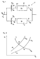
- FIG. 2 further shows a starting characteristic 24, which shows the maximum transferable clutch torque M K2 of the second clutch 21 as a function of the engine speed n M.
- the start-up characteristics 14, 24 depend on the engaged gear I, II of the respective partial transmission 10, 20 from. For example, if in the first partial transmission 10 other than the first forward gear I is engaged, then a completely different dependence of the clutch torque M K1 of the first clutch 11 may be deposited.
- FIG. 2 shows an engine characteristic curve M M of a specific engine load (for example 40% of the full load) or of a specific engine torque M M.
- the motor characteristic curve 3 intersects the starting characteristic curves 14, 24 at points of intersection 15, 25. At the intersection point 15, the gradient of the starting characteristic 14 is greater than the gradient of the motor characteristic curve 3. The same applies to the point of intersection 25.
- FIG. 3 shows various speed curves over time t for a shift of the invention from the first gear I to second gear II.
- the vehicle is stationary and the engine rotates at idle speed n 0 .
- a certain engine load is set, so that the engine speed n M (thick solid line) increases starting from the time t 0 .
- the starting characteristic 14 cf. FIG. 2
- the transmittable clutch torque M K1 is greater, so that the vehicle is further accelerated.
- the engine speed n M thereby runs along a characteristic n M1 (dashed line), which equals the speed n E1 as the time progresses.
- the characteristic curve n M1 thus indicates the profile of the engine speed n M when not switched when starting the vehicle and the vehicle is first accelerated with the first gear until the engine speed n M of the rotational speed n E1 of the first input shaft 12 and the clutch 11 works without slippage.
- the clutch torque of the first clutch 11 is reduced by means of a degradation function F Ab
- the clutch torque M k2 of the second clutch 21 is constructed via a body function F Auf .
- the construction function F up and the removal function F Ab are functions that are linear with respect to time t, with their gradients being dimensioned in another time t 2, it assumes the value 0 (applies to the degradation function F Ab ) or the value 1 (applies to the build-up function F Up ).
- the clutch torque M k1 of the first clutch 11 is reduced to a value 0 from a torque starting value which is applied to the first clutch 11 at time t 1 .
- the clutch torque M k2 of the second clutch 21 is built up from the value 0 at time t 1 to a value M k2 , which corresponds to a Drehmomentendwert at which the second gear and the engine speed dependent starting characteristic 24, the motor characteristic. 3 the predetermined engine load cuts. Accordingly, the engine speed n M runs at the time t 2 in the characteristic n M2 , which represents the engine speed, if it would be approached only with the second gear.
- the engine speed n M intersects the speed n E1 of the first input shaft 12. This means that the engine rotates slower than the first input shaft 12. If, after time t 2 , the first clutch 11 continues to transmit torque, the engine brakes Motor from the first input shaft 12, while it drives the second input shaft 22 via the second clutch 21. This would lead to a distortion of the dual-clutch transmission 1, but this is accompanied within certain limits without loss of comfort. If there is greater tension, this can be compensated by increasing the engine torque M M.
- FIG. 4 shows a flowchart for calculating the torque capacity or clutch torque M k1 and M k2 of the clutches 11, 21.
- the clutch torque of the first clutch according to the starting characteristic 14 certainly.
- the clutch torque depends on the engine speed n M , but may also depend on other factors such as the speed n E1 of the input shaft 12, the speed n E2 of the second input shaft 22, the time t and the speed v of the vehicle.
- the torque calculation takes place in accordance with starting characteristic 24 (cf. FIG. 2 ) for the second clutch 21 (see block 26 in FIG. 4 ).
- the degradation function F Ab is determined, which is performed linearly with time t from a start value 1 time t 1 to a final value 0 at time t 2 .
- the clutch torque of the first clutch 12 according to the starting characteristic 14 and the degradation function F Ab are multiplied in the link 17 with each other, wherein the product resulting from this link 17 the coupling torque M k1 of first clutch 12 during the shift corresponds.
- the clutch torque M k2 of the second clutch 22 is calculated by multiplying the torque according to start-up characteristic 24 and the build-up function F Auf in a link 27.
- the construction function F Auf corresponds to the difference 1 - F Ab .
- FIG. 5 shows different speed curves of a further embodiment of the invention.
- An essential difference to the embodiment according to FIG. 3 consists in that an adaptation of the engine speed n M to the speed n E2 of the second input shaft 22 takes place only after a time t 4 .
- the second clutch 21 is guided to an intermediate value M ZW , wherein the engine speed n M further corresponds to the rotational speed of the first input shaft 12.
- the flowchart of FIG. 6 can also be removed, again on the degradation function F Ab and on the build function F on .
- the functions F Ab , F On are also linearly dependent on the time t.
- the intermediate value M ZW and the clutch torque according to the starting characteristic 24 may depend on the engine speed n M , the rotational speeds n E1 , n E2 of the input shafts 12, 22, the speed v of the vehicle, the time t and / or the driver's desired torque M W.
- the multiplication of the intermediate value M ZW and the degradation function F Ab takes place in the flowchart of FIG FIG. 6 in a link 28.
- the summands described above are added in a link 29, the sum corresponding to the clutch torque M k2 of the second clutch 22.
- the engine speed n M is adjusted starting from the time t 4 of the rotational speed n E1 of the first input shaft to the rotational speed n E2 of the second input shaft 22.
Landscapes
- Engineering & Computer Science (AREA)
- General Engineering & Computer Science (AREA)
- Mechanical Engineering (AREA)
- Physics & Mathematics (AREA)
- Fluid Mechanics (AREA)
- Control Of Transmission Device (AREA)
Abstract
Description
- Die Erfindung betrifft ein Verfahren zum Schalten eines Doppelkupplungsgetriebes in einem mit einem Motor betriebenen Fahrzeug, mit einer ersten Kupplung und mit einer zweiten Kupplung sowie mit einem ersten Teilgetriebe und einem zweiten Teilgetriebe, wobei dem ersten Teilgetriebe die erste Kupplung und eine erste Gruppe von Gängen und dem zweiten Teilgetriebe die zweite Kupplung und eine zweite Gruppe von Gängen zugeordnet sind.
- Bei Doppelkupplungsgetrieben wird das Schalten bzw. der Gangwechsel normalerweise auf eine von zwei Arten vorgenommen: Bei Zughoch- und Schubrückschaltungen wird zuerst im zweiten Teilgetriebe, das vor dem Schalten kein Drehmoment übertragen soll, ein Zielgang eingelegt. Danach wird das anliegende Motormoment gemäß einer vorgegebenen Motorlast von der ersten Kupplung auf die zweite Kupplung übertragen. Dabei wird die zweite passive Kupplung unter Schlupf so geregelt, dass die Motordrehzahl der Drehzahl einer Eingangswelle des ersten Teilgetriebes entspricht. Im Anschluss daran wird die Motordrehzahl durch Reduktion des Motormomentes und Regelung der Drehmomentkapazität der zweiten Kupplung auf die Drehzahl einer Eingangswelle des zweiten Teilgetriebes geregelt. Danach kann die zweite Kupplung vollständig geschlossen werden. Eine derartige Regelung der Drehmomentkapazitäten der ersten und zweiten Kupplung sowie der sich anschließenden Anpassung der Motordrehzahl an die Drehzahl der zweiten Eingangswelle des zweiten Teilgetriebes ist in der
EP 1 507 103 B1 offenbart. - Bei Zugrückschaltungen oder Schubhochschaltungen wird die Reihenfolge der Drehmomentübergabe (Abbau der Drehmomentkapazität der ersten Kupplung bei gleichzeitigem Aufbau der Drehmomentkapazität der zweiten Kupplung) und der Anpassung der Motordrehzahl vertauscht: Zuerst wird die erste Kupplung in Schlupf gebracht und die Motordrehzahl auf die Drehzahl der Eingangswelle des zweiten Teilgetriebes angehoben. Davor oder während dessen wird in dem zweiten Teilgetriebe der Zielgang eingelegt. Sobald die Motordrehzahl der Drehzahl der Eingangswelle des zweiten Teilgetriebes entspricht, wird das Drehmoment von der ersten Kupplung (noch aktiven Kupplung) auf die zweite Kupplung (bisher passive Kupplung) übergeben und damit die Schaltung abgeschlossen.
- Diese Arten der Schaltung haben zwei Einschränkungen, die sie für die Benutzung während eines Anfahrens des Fahrzeugs unvorteilhaft erscheinen lassen: Zum einen funktionieren sie am besten, wenn sich die Motordrehzahl zwischen den Drehzahlen der beiden Eingangswellen befindet, zum anderen ist diese Schaltung sehr sensitiv gegenüber wechselnden Motordrehmomenten oder -lasten (z.B. aufgrund wechselnder Fahrpedalstellungen).
- Beim Anfahren befindet sich die Motordrehzahl üblicher Weise oberhalb von den Drehzahlen der beiden Eingangswellen der Teilgetriebe, in denen üblicher Weise einerseits ein erster Vorwärtsgang und andererseits ein zweiter Vorwärtsgang des Fahrzeugs vorgewählt sind. Ebenfalls sollte aus Komfortgründen die Schaltung über einen längeren Zeitraum erfolgen und ist somit besonders anfällig gegenüber wechselnden Gaspedalstellungen, die speziell in Rangiersituationen während des Anfahrens sehr häufig vorkommen. Auch können mit dem oben beschriebenen Verfahren keine Schaltungen abgewickelt werden, bei denen die Drehzahl der Eingangwelle des zweiten Teilgetriebes unterhalb der Motor-Leerlaufdrehzahl liegt. Dadurch werden frühe Hochschaltungen, die bei niedrigen Fahrpedalstellungen aufgrund des normalerweise großen Stufensprungs wünschenswert sind, unmöglich.
- Der Erfindung liegt daher die Aufgabe zugrunde, ein neues verbessertes Verfahren zum Schalten des Doppelkupplungsgetriebes während des Anfahrens des Fahrzeugs bereits zu stellen.
- Die der Erfindung zugrunde liegende Aufgabe wird mit dem Verfahren gemäß Anspruch 1 gelöst. Bevorzugte Ausführungsbeispiele können den Unteransprüchen entnommen werden.
- Das erfindungsgemäße Verfahren zeichnet sich dadurch aus, dass die Anpassung der Motordrehzahl über den Aufbau der Drehmomentkapazität der zweiten Kupplung erfolgt, wobei die Drehmomentkapazität der zweiten Kupplung auf einen Drehmomentendwert geführt wird, bei dem eine vom Zielgang und von der Motordrehzahl abhängige Anfahrkennlinie eine Motorkennlinie einer vorgegebenen Motorlast schneidet. Somit wird beim Schalten eine Fahrstrategie ausgenutzt, die über die Anfahrkennlinie des Zielgangs implementiert ist. Bei dieser Anfahrkennlinie wird das übertragbare Drehmoment oder die Drehmomentkapazität der zweiten Kupplung in Abhängigkeit von der Motordrehzahl (und/oder gegebenenfalls der Fahrzeuggeschwindigkeit) bestimmt. Diese Abhängigkeit wird nun für einen zweiten (Vorwärts-) Gang des Doppelkupplungsgetriebes, der dem zweiten Teilgetriebe zugeordnet ist, anders gestaltet als für einen ersten (Vorwärts-)Gang des Doppelkupplungsgetriebes, der dem ersten Teilgetriebe zugeordnet ist, und zwar zweckmäßigerweise in der Gestalt, dass für das gleiche Kupplungsmoment im höheren Gang eine geringere Motordrehzahl notwendig ist. Somit weist die Anfahrkennlinie des zweiten Ganges bei gleicher Motordrehzahl größere Drehmomentwerte als die Anfahrkennlinie des ersten Ganges auf.
- Vorzugsweise steigt die vom Zielgang abhängige Anfahrkennlinie (Anfahrkennlinie des Zielganges) mit der Motordrehzahl monoton stetig und weist im Schnittpunkt mit der Motorkennlinie eine Steigung auf, die größer als die Steigung der Motorkennlinie in diesem Schnittpunkt ist. Dadurch wird sichergestellt, dass bei dem Aufbau der Drehmomentkapazität der zweiten Kupplung der Motor sicher die Motordrehzahl erreicht, in dem sich die Anfahrkennlinie des Zielgangs und die Motorkennlinie mit der vorgegebenen Motorlast schneiden. Es sei an dieser Stelle darauf hingewiesen, dass sich während des Schaltens die Motorlast aufgrund einer geänderten Pedalstellung ändern kann. In diesem Fall entspricht die vorgegebene Motorlast der augenblicklichen Motorlast.
- Zeitgleich mit dem Aufbau der Drehmomentkapazität der zweiten Kupplung erfolgt der Abbau der Drehmomentkapazität der ersten Kupplung, wobei vorzugsweise die Drehmomentkapazität der ersten Kupplung ausgehend von einem Drehmomentstartwert, bei dem eine vom Startgang und der Motordrehzahl abhängige Anfahrkennlinie die Motorkennlinie der vorgegebenen Motorlast schneidet, auf einen Wert 0 geführt wird. Somit ist auch für den Startgang eine Anfahrkennlinie hinterlegt, die die Drehmomentkapazität der ersten Kupplung für den Startgang in Abhängigkeit der Motordrehzahl festlegt. Nach dem Schalten kann die Drehmomentkapazität der ersten Kupplung auch Werte ungleich 0 annehmen, wobei dann aber nur sehr kleine Drehmomente übertragen werden können. Beispielsweise kann es zwecks Regelung der Kupplung gewünscht sein, dass auch bei passiv gestellter Kupplung noch eine sehr kleine Drehmomentkapazität gestellt ist.
- Vorzugsweise steigt die vom Startgang abhängige Anfahrkennlinie (Anfahrkennlinie des Startganges) mit der Motordrehzahl monoton stetig an und weist im Schnittpunkt mit der Motorkennlinie der vorgegebenen Motorlast eine Steigung auf, die größer ist als die Steigung der Motorkennlinie in diesem Schnittpunkt. Durch die stetig ansteigenden Anfahrkennlinien, den definierten Schnittpunkten mit der Motorkennlinie und mit den Verhältnissen der Steigungen in den Schnittpunkten (Anfahrkennlinie weist im Schnittpunkt eine höhere Steigung als die Motorkennlinie auf) erfolgt eine stabile und eindeutige Anpassung der Motordrehzahl, wenn die Drehmomentkapazität der ersten Kupplung abgebaut und die Drehmomentkapazität der zweiten Kupplung aufgebaut wird.
- Vorzugsweise ist zum Beginn des Schaltvorgangs die Motordrehzahl größer als die Drehzahl der Eingangswelle des ersten Teilgetriebes.
- Wird nun eine Schaltung während des Anfahrens (Motordrehzahl ist größer als die Drehzahl der Eingangswelle des ersten Teilgetriebes) angefordert, wird das Motormoment von der ersten Kupplung auf die zweite Kupplung übergeblendet. Dies bewirkt aufgrund der Anfahrkennlinien automatisch eine Anpassung der Motordrehzahl, so dass bei dieser Schaltung die Drehmomentenübergabe von der ersten Kupplung auf die zweite Kupplung und die Anpassung der Motordrehzahl gleichzeitig geschehen. Da die Anfahrkennlinien robust gegenüber sich ändernden Pedalstellungen sind, ist auch die aus der Drehmomentübergabe resultierende Drehmomentverteilung robust, so dass auch während der Schaltung ein sich änderndes Motordrehmoment akzeptiert werden kann. Ebenfalls kann die Schaltung leicht rückabgewickelt werden, in dem die Drehmomentübergabe zurückgenommen wird.
- Die Drehmomentkapazität der zweiten Kupplung kann dem Produkt des Drehmomentendwertes gemäß Anfahrkennlinie und einer Aufbaufunktion FAuf entsprechen, die mit dem Wert 0 beginnt und mit dem Wert 1 endet. Die Drehmomentkapazität der ersten Kupplung kann einem Produkt des Drehmomentstartwertes und einer Abbaufunktion FAb entsprechen, die mit dem Wert 1 beginnt und mit dem Wert 0 endet. Die Aufbaufunktion FAuf und/oder die Abbaufunktion FAb können linear von der Motordrehzahl oder der Zeit abhängen. In einem bevorzugten Ausführungsbeispiel gilt dabei: FAb = 1 - FAuf. Eine weitere Möglichkeit besteht darin, die Drehmomentkapazität der ersten und zweiten Kupplung mit jeweils eigener Funktion oder mit einem eigenen Faktor zu versehen, wobei die beiden Faktoren in geeigneter Weise gegenläufig sind und so ein Überblenden der Kupplungsmomente realisieren. Auf diese Weise können Verzögerungen im Systemverhalten ausgeglichen werden, in dem sie in den Verläufen der Faktoren vorgehalten werden. Die Funktionen FAuf, FAb können, wie oben bereits beschrieben, linear oder variabel über ein Kennfeld oder eine Kennfunktion abgebildet sein. Sie können von der Zeit, der Fahrzeuggeschwindigkeit, der Motordrehzahl und/oder dem Motor- bzw. Fahrerwunschmoment abhängen. Auch ist eine gegenseitige Beeinflussung der Einflussgrößen möglich (z.B. eine zeitabhängige Charakteristik, bei der die Übergabezeit von dem Fahrerwunschmoment abhängt).
- Die Ausgestaltung der beiden Anfahrkennlinien kann von der Drehmomentcharakteristik des Motors und der Abhängigkeit dieser Charakteristik von dem gewählten Gang abhängen. Um nach der Schaltung die gleiche Beschleunigung des Fahrzeugs zu haben, muss das Motormoment im zweiten Gang bei der gewünschten Drehzahl nach der Schaltung um den Faktor des Verhältnisses der Gangübersetzungen höher sein als im ersten Gang bei der Ausgangsdrehzahl. Dies entspricht in der Regel nicht der Charakteristik, die normalerweise für eine Schaltung benötigt wird, bei der sich sowohl die Drehzahl als auch das Drehmoment nach der Schaltung mit dem Verhältnis der Gangübersetzungen ändern.
- Bei der Anpassung der Motordrehzahl kann ein Motoreingriff erfolgen, um den Einfluss von Trägheitsmomenten, bedingt durch ein Abbremsen des Motors, auszugleichen. Da die Übergabe jedoch in der Regel länger dauert als bei Schaltungen, wie sie aus dem Stand der Technik bekannt sind, kann der Motoreingriff deutlich niedriger ausfallen.
- Vorzugsweise ist der Abbau der Drehmomentkapazität der ersten Kupplung abgeschlossen, bevor die Motordrehzahl die Drehzahl der Eingangswelle des ersten Teilgetriebes unterschreitet, da sonst ein Verspannungszustand erzeugt wird, bei dem die Eingangswelle des ersten Teilgetriebes nicht weiter beschleunigt, sondern abgebremst würde. Dieser Verspannungszustand ist jedoch bei niedrigen Drehmomenten sehr gering, so dass eine deutliche Überlappung zugelassen werden kann. So ist in einem Ausführungsbeispiel bei niedrigen Pedalstellungen und damit bei nierdrigen Drehmomenten zulässig, die Überblendfunktion bis zu 50% durchzuführen, nachdem die Motordrehzahl die Drehzahl der Eingangswelle des ersten Teilgetriebes unterschritten hat, ohne dass eine zu große Komforteinbuße hingenommen werden braucht.
- Höhere Überlappungsraten können erzielt werden, indem das Motormoment entsprechend dem Verspannungszustand erhöht wird. Beträgt z.B. der Motormoment 50 Nm, die Drehmomentkapazität der ersten Kupplung noch 30 Nm und die Drehmomentkapazität der zweiten Kupplung 45 Nm (bei einem Gangsprung, also dem Verhältnis der Gangübersetzungen von 1,5), so kann durch eine Erhöhung des Motormomentes und der Drehmomentkapazität der zweiten Kupplung um jeweils 45 Nm ein Verspannungszustand bei Unterschreiten der Drehzahl der Eingangswelle des ersten Teilgetriebes ausgeglichen werden. Da im Laufe der Drehzahlanpassung auch das Drehmoment der ersten Kupplung abgebaut wird, kann auch parallel dazu die Drehmomentüberhöhung des Motors und der zweiten Kupplung zurückgefahren werden. Diese Methode empfiehlt sich hauptsächlich dann, wenn aufgrund von äußeren Umständen (z.B. Einfahrt in eine Steigung) die Schaltung aufgrund sich verändernder Verhältnisse in einen Verspannungsbereich hineinläuft. Durch entsprechenden Motoreingriff kann hier ohne Komforteinbußen die Schaltung zu Ende abgewickelt werden.
- Wenn zum Beginn des Schaltvorgangs die Motordrehzahl der Drehzahl der Eingangswelle des ersten Teilgetriebes entspricht, kann die Drehmomentkapazität der zweiten Kupplung bei konstanter bzw. nicht angepasster Motordrehzahl bis auf einen Zwischenwert geführt werden, von dem aus die Drehmomentkapazität der zweiten Kupplung auf den Drehmomentendwert der Anfahrkennlinie geführt wird, wobei die Motordrehzahl in Richtung der Eingangswelle des weiten Teilgetriebes angepasst wird. In diesem Ausführungsbeispiel - analog zur normalen Zughochschaltung - erfolgt zuerst eine Drehmomentübergabe auf die zweite Kupplung, wobei das Drehmoment der zweiten Kupplung zur Regelung der Motordrehzahl dient. Dadurch wird bei gleich bleibenden Drehzahlverhältnissen das Drehmoment auf die zweite Kupplung übertragen. Im Anschluss daran erfolgt der Aufbau der Drehmomentkapazität gemäß Anfahrkennlinie der zweiten Kupplung. Dabei darf der Zwischenwert der Drehmomentkapazität der zweiten Kupplung, der mit der Abbaufunktion FAb abgebaut wird, jedoch nicht mehr durch die Motordrehzahl geregelt werden, sondern muss konstant gehalten werden bzw. darf nur durch das geschätzte Motormoment beeinflusst werden. Dadurch wird eine Drehzahl- und Drehmomentanpassung an die Anfahrkennlinie der zweiten Kupplung durchgeführt.
- Zusammenfassend stellt somit die vorliegende Erfindung ein Verfahren zum Schalten eines Doppelkupplungsgetriebes bereit, wobei die Drehmomentübergabe von der ersten Kupplung auf die zweite Kupplung gleichzeitig mit der Anpassung der Motordrehzahl erfolgt, indem von der Anfahrkennlinie des Startganges auf die Anfahrkennlinie des Zielganges durch entsprechende Funktionen (abbauende Funktion FAb, aufbauende FAuf) übergeblendet wird. Beim Schalten liegt dabei während des größten Teils der Zeit die Motordrehzahl über den Drehzahlen der beiden Eingangswellen des Doppelkupplungsgetriebes.
- Bei einer Schaltung von einer nicht schlupfenden oder tragenden ersten Kupplung zu einer schlupfenden zweiten Kupplung kann erfindungsgemäß zuerst eine Drehmomentübergabe ohne Anpassung der Motordrehzahl stattfinden, wobei während der anschließenden Anpassung der Motordrehzahl ebenfalls die Drehmomentkapazität der zweiten Kupplung auf den Drehmomentendwert gemäß Anfahrkennlinie geführt wird.
- Anhand der in der Zeichnung dargestellten Ausführungsbeispiele wird die Erfindung näher erläutert. Es zeigen:
- Figur 1
- den schematischen Aufbau eines Doppelkupplungsgetriebes;
- Figur 2
- Anfahrkennlinien eines ersten Ganges und eines zweiten Ganges sowie eine Motorkennlinie;
- Figur 3
- diverse Drehzahlverläufe während eines Schaltvorgangs gemäß einem ersten Ausführungsbeispiel;
- Figur 4
- ein Ablaufdiagramm gemäß erstem Ausführungsbeispiel;
- Figur 5
- diverse Drehzahlverläufe während eines Schaltvorgangs gemäß einem zweiten Ausführungsbeispiel; und
- Figur 6
- ein Ablaufdiagramm gemäß dem zweiten Ausführungsbeispiel.
-
Figur 1 zeigt einen schematischen Aufbau eines Doppelkupplungsgetriebes, das in seiner Gesamtheit mit 1 bezeichnet wird. Das Doppelkupplungsgetriebe 1 weist ein erstes Teilgetriebe 10 und ein zweites Teilgetriebe 20 auf. Dem ersten Teilgetriebe 10 ist eine erste Kupplung 11 zugeordnet, während dem zweiten Teilgetriebe 20 eine zweite Kupplung 21 zugeordnet ist. Mit der ersten Kupplung 11 lässt sich eine Drehung einer Kurbelwelle 2 eines hier nicht dargestellten Motors auf eine Eingangswelle 12 des ersten Teilgetriebes 10 übertragen. Bei einer vollständig geschlossenen Kupplung 11 entspricht eine Motordrehzahl nM des Motors bzw. der Kurbelwelle 2 einer Drehzahl nE1 der Eingangswelle 12. Analog lassen sich mit der zweiten Kupplung 21 die Kurbelwelle 2 und eine Eingangswelle 22 des zweiten Teilgetriebes 20 miteinander koppeln, so dass die Motordrehzahl nM der Drehzahl nE2 der Eingangswelle 22 entspricht. - Dem ersten Teilgetriebe 10 ist eine erste Gruppe von Gängen zugeordnet, unter denen sich auch ein erster (Vorwärts-) Gang I des Doppelgetriebes 1 befinden soll. Üblicher Weise sind dem ersten Teilgetriebe 10 weitere ungerade Vorwärtsgänge zugeordnet, auf die aber hier nicht weiter eingegangen wird. Dem zweiten Teilgetriebe 20 ist eine zweite Gruppe von Gängen zugeordnet, die einen zweiten (Vorwärts-) Gang II umfassen soll. Auf weitere Vorwärtsgänge des zweiten Teilgetriebes 20 wird hier nicht näher eingegangen.
- Eine Ausgangswelle 13 des ersten Teilgetriebes 10 dreht sich mit einer Drehzahl nA1, wobei das Verhältnis der Drehzahlen nA1 zu nE1 von dem im ersten Teilgetriebe 10 eingelegten Gang abhängig ist. Analog zum ersten Teilgetriebe 10 weist auch das zweite Teilgetriebe 20 eine Ausgangswelle 23 auf, die sich mit einer Drehzahl nA2 dreht. Die Drehzahl nA2 lässt sich aus der nE2 der Eingangswelle 22 und dem Übersetzungsverhältnis des in den zweiten Teilgetriebe 20 eingelegten Ganges bestimmen. Die Ausgangswellen 13, 23 sind über eine gemeinsame Abtriebseinheit (nicht dargestellt) miteinander gekoppelt, sodass die Drehzahlen nA1 und nA2 gleich groß sind oder zumindest in einem festen Verhältnis zueinander stehen.
- Die Drehmomentkapazität oder das maximal übertragbare Kupplungsmoment MK2 der ersten Kupplung 11 kann über eine Anfahrkennlinie 14, so wie sie in
Figur 2 dargestellt ist, in Abhängigkeit der Motordrehzahl nM eingestellt werden. Die Anfahrkennlinie 14 derFigur 2 steigt monoton stetig mit steigender Motordrehzahl nM an. Soweit ein an der Kurbelwelle 2 anliegendes Motormoment MM größer ist als die Drehmomentkapazität oder das übertragbare Kupplungsmoment MK1, überträgt die erste Kupplung 11 genau dieses Kupplungsmoment MK1 auf die Eingangswelle 12 des Teilgetriebes 10. -
Figur 2 zeigt des Weiteren eine Anfahrkennlinie 24, die in Abhängigkeit der Motordrehzahl nM das maximal übertragbare Kupplungsmoment MK2 der zweiten Kupplung 21 zeigt. Wie aus derFigur 2 ersichtlich, lassen sich mit der zweiten Kupplung 21 bei einer gleichen Motordrehzahl größere Drehmomente übertragen als mit der ersten Kupplung 11. Die Anfahrkennlinien 14, 24 hängen vom eingelegten Gang I, II des jeweiligen Teilgetriebes 10, 20 ab. Ist beispielsweise im ersten Teilgetriebe 10 ein anderer als der erste Vorwärtsgang I eingelegt, so kann eine vollständig andere Abhängigkeit des Kupplungsmomentes MK1 der ersten Kupplung 11 hinterlegt sein. - Neben den Anfahrkennlinien 14, 24 zeigt
Figur 2 auch eine Motorkennlinie MM einer bestimmten Motorlast (beispielsweise 40 % der Volllast) bzw. eines bestimmten Motormomentes MM. Die Motorkennlinie 3 schneidet die Anfahrkennlinien 14, 24 in Schnittpunkten 15, 25. Im Schnittpunkt 15 ist die Steigung der Anfahrkennlinie 14 größer als die Steigung der Motorkennlinie 3. Entsprechendes gilt für den Schnittpunkt 25. -
Figur 3 zeigt diverse Drehzahlverläufe über der Zeit t für einen erfindungsgemäßen Schaltvorgang vom ersten Gang I zum zweiten Gang II. Zu einem Zeitpunkt t0 steht das Fahrzeug still und der Motor dreht mit der Leerlaufdrehzahl n0. Bei eingelegtem ersten Gang I wird eine bestimmte Motorlast eingestellt, so dass die Motordrehzahl nM (dicke durchgezogene Linie) ausgehend vom Zeitpunkt t0 ansteigt. Gemäß der Anfahrkennlinie 14 (vgl.Figur 2 ) steigt mit der Motordrehzahl nM das übertragbare Kupplungsmoment MK1 der ersten Kupplung 11, wodurch das Fahrzeug beschleunigt wird und die Drehzahl nE1 der Eingangswelle 12 ansteigt. Mit größer werdender Motordrehzahl nM wird auch das übertragbare Kupplungsmoment MK1 größer, so dass das Fahrzeug weiter beschleunigt wird. Die Motordrehzahl nM verläuft dabei entlang einer Kennlinie nM1 (gestrichelte Linie), die sich mit fortschreitender Zeit der Drehzahl nE1 angleicht. Die Kennlinie nM1 zeigt somit den Verlauf der Motordrehzahl nM an, wenn beim Anfahren des Fahrzeugs nicht geschaltet wird und das Fahrzeug mit dem ersten Gang solang beschleunigt wird, bis die Motordrehzahl nM der Drehzahl nE1 der ersten Eingangswelle 12 entspricht und die Kupplung 11 schlupffrei arbeitet. - Im vorliegenden Fall jedoch wird beim Anfahren vom ersten Gang 1 in den zweiten Gang II geschaltet. Dazu wird in einem Zeitpunkt t1 das Kupplungsmoment der ersten Kupplung 11 mittels einer Abbaufunktion FAb reduziert, während gleichzeitig das Kupplungsmoment Mk2 der zweiten Kupplung 21 über eine Aufbaufunktion FAuf aufgebaut wird. Die Aufbaufunktion FAuf und die Abbaufunktion FAb sind dabei Funktionen, die sich linear zur Zeit t verhalten, wobei deren Steigungen so bemessen sind, dass sie in einem weiteren Zeitpunkt t2 den Wert 0 (gilt für die Abbaufunktion FAb) bzw. den Wert 1 (gilt für die Aufbaufunktion FAuf) annehmen. Durch die Funktionen FAuf, FAb wird das Kupplungsmoment Mk1 der ersten Kupplung 11 von einem Drehmomentstartwert, der zum Zeitpunkt t1 an der ersten Kupplung 11 anliegt, auf den Wert 0 reduziert. Durch die Aufbaufunktion FAuf wird das Kupplungsmoment Mk2 der zweiten Kupplung 21 ausgehend vom Wert 0 im Zeitpunkt t1 auf einen Wert Mk2 aufgebaut, der einem Drehmomentendwert entspricht, bei dem die vom zweiten Gang und von der Motordrehzahl abhängige Anfahrkennlinie 24 die Motorkennlinie 3 der vorgegebenen Motorlast schneidet. Entsprechend läuft die Motordrehzahl nM im Zeitpunkt t2 in die Kennlinie nM2, die die Motordrehzahl darstellt, wenn nur mit dem zweiten Gang angefahren werden würde. Im Zeitpunkt t2 schneidet zudem die Motordrehzahl nM die Drehzahl nE1 der ersten Eingangswelle 12. Dies bedeutet, dass der Motor langsamer dreht als die erste Eingangswelle 12. Würde nach dem Zeitpunkt t2 weiterhin die erste Kupplung 11 ein Drehmoment übertragen, bremst der Motor die erste Eingangswelle 12 ab, während er über die zweite Kupplung 21 die zweite Eingangswelle 22 antreibt. Dies würde zu einer Verspannung des Doppelkupplungsgetriebes 1 führen, die aber in gewissen Grenzen ohne Komforteinbußen einhergeht. Kommt es zu größeren Verspannungen, so kann diese durch eine Erhöhung des Motormomentes MM ausgeglichen werden.
-
Figur 4 zeigt ein Ablaufdiagramm zum Berechnen der Drehmomentkapazitäten oder Kupplungsmomente Mk1 und Mk2 der Kupplungen 11, 21. In dem Block 16 wird das Kupplungsmoment der ersten Kupplung gemäß der Anfahrkennlinie 14 (vgl.Figur 2 ) bestimmt. Das Kupplungsmoment hängt dabei von der Motordrehzahl nM ab, kann aber auch noch von weiteren Faktoren wie die Drehzahl nE1 der Eingangswelle 12, der Drehzahl nE2 der zweiten Eingangswelle 22, der Zeit t und der Geschwindigkeit v des Fahrzeugs abhängen. In analoger Weise erfolgt die Momentenberechnung gemäß Anfahrkennlinie 24 (vgl.Figur 2 ) für die zweite Kupplung 21 (siehe Block 26 inFigur 4 ). Im Block 5 wird die Abbaufunktion FAb bestimmt, die linear mit der Zeit t von einem Startwert 1 Zeitpunkt t1 auf einen Endwert 0 im Zeitpunkt t2 geführt wird. Das Kupplungsmoment der ersten Kupplung 12 gemäß der Anfahrkennlinie 14 und die Abbaufunktion FAb werden in der Verknüpfung 17 miteinander multipliziert, wobei das durch diese Verknüpfung 17 entstehende Produkt dem Kupplungsmoment Mk1 der ersten Kupplung 12 während des Schaltens entspricht. Das Kupplungsmoment Mk2 der zweiten Kupplung 22 wird durch Multiplikation des Drehmoments gemäß Anfahrkennlinie 24 und der Aufbaufunktion FAuf in einer Verknüpfung 27 berechnet. Die Aufbaufunktion FAuf entspricht dabei der Differenz 1 - FAb. -
Figur 5 zeigt verschiedene Drehzahlverläufe eines weiteren Ausführungsbeispiels der Erfindung. Ein wesentlicher Unterschied zum Ausführungsbeispiel gemäßFigur 3 besteht darin, dass eine Anpassung der Motordrehzahl nM an die Drehzahl nE2 der zweiten Eingangswelle 22 erst nach einem Zeitpunkt t4 erfolgt. Zuvor wird in einem Zeitraum zwischen einem Zeitpunkt t3 und dem Zeitpunkt t4 das Drehmoment von der ersten Kupplung 12 auf die zweite Kupplung 22 übergeblendet, wobei jedoch die erste Kupplung 12 nicht schlupft und lediglich die zweite Kupplung 22 unter Schlupf betrieben wird. Somit wird die zweite Kupplung 21 auf einen Zwischenwert MZW geführt, wobei die Motordrehzahl nM weiterhin der Drehzahl der ersten Eingangswelle 12 entspricht. Ausgehend von dem Zwischenwert MZW erfolgt eine Erhöhung des Kupplungsmomentes Mk2 der zweiten Kupplung 22. Dies erfolgt, was dem Ablaufdiagramm derFigur 6 ebenfalls entnommen werden kann, wiederum über die Abbaufunktion FAb und über die Aufbaufunktion FAuf. Die Funktionen FAb, FAuf sind hier ebenfalls von der Zeit t linear abhängig. - Das durch das Ablaufdiagramm der
Figur 6 berechnete Kupplungsmoment Mk2 der zweiten Kupplung 21, das zur Anpassung der Motordrehzahl nM an die Drehzahl nE2 der zweiten Eingangswelle 22 dient, stellt sich als Summe zweier Summanden dar: Der erste Summand entspricht dabei dem Kupplungsmoment gemäß Anfahrkennlinie 24 (siehe Block 26') zusammen, wobei dieses Drehmoment mit der Aufbaufunktion FAuf in einer Verknüpfung 27' multipliziert wird. Der zweite Summand entspricht einem Produkt aus dem Zwischenwert MZW des Drehmomentes der zweiten Kupplung 22 nach erfolgter Drehmomentüberblendung und der von der Zeit t abhängigen Abbaufunktion FAb. Der Zwischenwert MZW und das Kupplungsmoment gemäß Anfahrkennlinie 24 können von der Motordrehzahl nM, von der Drehzahlen nE1, nE2 der Eingangswellen 12, 22, der Geschwindigkeit v des Fahrzeugs, der Zeit t und/oder dem Fahrerwunschmoment MW abhängen. Die Multiplikation des Zwischenwertes MZW und der Abbaufunktion FAb erfolgt im Ablaufdiagramm derFigur 6 in einer Verknüpfung 28. In einer Verknüpfung 29 werden die oben beschriebenen Summanden addiert, wobei die Summe dem Kupplungsmoment Mk2 der zweiten Kupplung 22 entspricht. - Wie der
Figur 5 zu entnehmen ist, wird die Motordrehzahl nM ausgehend vom Zeitpunkt t4 von der Drehzahl nE1 der ersten Eingangswelle auf die Drehzahl nE2 der zweiten Eingangswelle 22 angepasst. -
- 1
- Doppelkupplungsgetriebe
- 2
- Kurbelwelle
- 3
- Motorkennlinie
- 4
- Block
- 5
- Block
- 6
- Block
- 10
- erstes Teilgetriebe
- 11
- erste Kupplung
- 12
- Eingangswelle
- 13
- Ausgangswelle
- 14
- Anfahrkennlinie
- 15
- Schnittpunkt
- 16
- Block
- 17
- Verknüpfung
- 20
- zweites Teilgetriebe
- 21
- zweite Kupplung
- 22
- Eingangswelle
- 23
- Ausgangswelle
- 24
- Anfahrkennlinie
- 25
- Schnittpunkt
- 26
- Block
- 27
- Block
- 28
- Verknüpfung
- 29
- Verknüpfung
Claims (12)
- Verfahren zum Schalten eines Doppelkupplungsgetriebes (1) in einem mit einem Motor betriebenen Fahrzeug, mit einer ersten Kupplung (11) und mit einer zweiten Kupplung (22) sowie mit einem ersten Teilgetriebe (10) und einem zweiten Teilgetriebe (20), wobei dem ersten Teilgetriebe (10) die erste Kupplung (11) und eine erste Gruppe von Gängen und dem zweiten Teilgetriebe (20) die zweite Kupplung (21) und eine zweite Gruppe von Gängen zugeordnet sind, umfassend folgende Verfahrensschritte, um das Doppelkupplungsgetriebe (1) bei einer vorgegebenen Motorlast von einem Startgang, der der ersten Gruppe von Gängen angehört, in einen Zielgang zu schalten, der der zweiten Gruppe von Gängen angehört:a) Abbau einer Drehmomentkapazität (MK1) der ersten Kupplung (11)b) Aufbau einer Drehmomentkapazität (MK2) der zweiten Kupplung (21)c) Anpassung einer Motordrehzahl (nM) des Motors in Richtung einer Drehzahl (nE2) einer Eingangswelle (22) des zweiten Teilgetriebes (20),dadurch gekennzeichnet, dass die Anpassung der Motordrehzahl (nM) über den Aufbau der Drehmomentkapazität (MK2) der zweiten Kupplung (21) erfolgt, wobei die Drehmomentkapazität (MK2) der zweiten Kupplung (21) auf einen Drehmomentendwert geführt wird, bei dem eine vom Zielgang und von der Motordrehzahl (nM) abhängige Anfahrkennlinie (24) eine Motorkennlinie (3) der vorgegebenen Motorlast schneidet.
- Verfahren nach Anspruch 1, dadurch gekennzeichnet, dass der Startgang ein 1. Gang (1) und der Zielgang ein 2. Gang (11) des Doppelkupplungsgetriebes (1) ist, wobei eine vom 1. Gang (I) abgängige Anfahrkennlinie (14) bei gleicher Motordrehzahl (nM) größere Drehmomentwerte aufweist.
- Verfahren nach Anspruch 1 oder 2, dadurch gekennzeichnet, dass die vom Zielgang abhängige Anfahrkennlinie (24) mit der Motordrehzahl (nM) monoton stetig steigt und im Schnittpunkt (25) mit der Motorkennlinie (3) eine größere Steigung als die Motorkennlinie (3) aufweist.
- Verfahren nach einem der Ansprüche 1 bis 3, dadurch gekennzeichnet, dass mit dem Aufbau der Drehmomentkapazität (MK2) der zweiten Kupplung (21) zeitgleich der Abbau der Drehmomentkapazität (MK1) der ersten Kupplung (11) erfolgt, wobei die Drehmomentkapazität (MK1) der ersten Kupplung (11) ausgehend von einem Drehmomentstartwert, bei dem die vom Startgang und der Motordrehzahl abhängige Anfahrkennlinie (14) die Motorkennlinie (3) der vorgegebenen Motorlast schneidet, auf einen Wert 0 geführt wird.
- Verfahren nach Anspruch 4, dadurch gekennzeichnet, dass die vom Startgang abhängige Anfahrkennlinie (14) mit der Motordrehzahl (nM) monoton steigt und im Schnittpunkt (15) mit der Motorkennlinie (3) eine größere Steigung als die Motorkennlinie aufweist.
- Verfahren nach einem der Ansprüche 1 bis 5, dadurch gekennzeichnet, dass zum Beginn des Schaltvorgangs die Motordrehzahl (nM) größer als die Drehzahl (nE1) einer Eingangswelle (12) des ersten Teilgetriebes (10) ist.
- Verfahren nach einem der Ansprüche 1 bis 6, dadurch gekennzeichnet, dass die Anpassung der Motordrehzahl (nM) mit dem Aufbau der Drehmomentkapazität (MK2) der zweiten Kupplung (21) beginnt.
- Verfahren nach einem der Ansprüche 1 bis 7, dadurch gekennzeichnet, dass die Drehmomentkapazität (MK2) der zweiten Kupplung (21) dem Produkt des Drehmomentendwertes und einer Aufbaufunktion (FAuf) entspricht, die mit dem Wert 0 beginnt und mit dem Wert 1 endet.
- Verfahren nach einem der Ansprüche 4 bis 8, dadurch gekennzeichnet, dass die Drehmomentkapazität (MK1) der ersten Kupplung (11) dem Produkt des Drehmomentstartwertes und einer Abbaufunktion (FAb) entspricht, die mit dem Wert 1 beginnt und mit dem Wert 0 endet.
- Verfahren nach Anspruch 8 oder 9, dadurch gekennzeichnet, dass die Aufbaufunktion (FAuf) und/oder die Abbaufunktion (FAb) linear von der Motordrehzahl (nM) oder der Zeit (t) abhängen.
- Verfahren nach einem der Ansprüche 1 bis 10, dadurch gekennzeichnet, dass bei Anpassung der Motordrehzahl (nM) ein Motoreingriff zum Ausgleich des Einfluss von Trägheitsmomenten erfolgt
- Verfahren nach einem der Ansprüche 1 bis 3 und 5 bis 11, dadurch gekennzeichnet, dass zum Beginn des Schaltvorgangs die Motordrehzahl (nM) der Drehzahl (nE1) der Eingangswelle (12) des ersten Teilgetriebes (10) entspricht und die Drehmomentkapazität (MK2) der zweiten Kupplung (21) bei nicht angepasster Motordrehzahl (nM) bis auf einem Zwischenwert (MZW) geführt wird, vom dem aus die Drehmomentkapazität (MK2) der zweiten Kupplung (21) auf den Drehmomentendwert der Anfahrkennlinie (24) geführt wird und die Motordrehzahl (nM) auf die Drehzahl (nE2) der Eingangswelle (22) des zweiten Teilgetriebes (20) geführt wird.
Applications Claiming Priority (1)
| Application Number | Priority Date | Filing Date | Title |
|---|---|---|---|
| DE102007057205 | 2007-11-26 |
Publications (2)
| Publication Number | Publication Date |
|---|---|
| EP2063152A1 true EP2063152A1 (de) | 2009-05-27 |
| EP2063152B1 EP2063152B1 (de) | 2011-02-02 |
Family
ID=40342610
Family Applications (1)
| Application Number | Title | Priority Date | Filing Date |
|---|---|---|---|
| EP08105379A Active EP2063152B1 (de) | 2007-11-26 | 2008-09-18 | Verfahren zum Schalten eines Doppelkupplungsgetriebes |
Country Status (3)
| Country | Link |
|---|---|
| US (1) | US8177685B2 (de) |
| EP (1) | EP2063152B1 (de) |
| DE (1) | DE502008002519D1 (de) |
Cited By (2)
| Publication number | Priority date | Publication date | Assignee | Title |
|---|---|---|---|---|
| WO2012143022A1 (de) * | 2011-04-20 | 2012-10-26 | Audi Ag | Verfahren zum betreiben eines kraftfahrzeugs im schubbetrieb |
| CN107599891A (zh) * | 2017-08-31 | 2018-01-19 | 北京新能源汽车股份有限公司 | 挡位切换方法和装置 |
Families Citing this family (10)
| Publication number | Priority date | Publication date | Assignee | Title |
|---|---|---|---|---|
| JP5017450B2 (ja) * | 2008-03-31 | 2012-09-05 | アイシン・エーアイ株式会社 | ハイブリッド動力装置 |
| DE102008040692A1 (de) * | 2008-07-24 | 2010-01-28 | Robert Bosch Gmbh | Verfahren und Vorrichtung zum Anfahren eines Hybridfahrzeuges |
| DE102010018532B3 (de) * | 2010-04-27 | 2011-07-07 | GETRAG FORD Transmissions GmbH, 50735 | Verfahren zum Schalten eines Doppelkupplungsgetriebes |
| DE102010044906A1 (de) * | 2010-09-09 | 2012-03-15 | Robert Bosch Gmbh | Verfahren zum Vergeben eines Betriebspunktes einer Antriebsmaschine eines Antriebssystems |
| US9897182B2 (en) * | 2012-07-24 | 2018-02-20 | Dti Group B.V. | Transmission system |
| US9790871B2 (en) | 2012-09-19 | 2017-10-17 | Yamaha Hatsudoki Kabushiki Kaisha | Control apparatus for vehicle, vehicle, and motor |
| KR101786126B1 (ko) * | 2012-10-26 | 2017-10-17 | 현대자동차주식회사 | 변속기 장착 ev차량의 모터토크 제어방법 |
| JP6512638B2 (ja) * | 2016-07-25 | 2019-05-15 | トヨタ自動車株式会社 | 車両の制御装置 |
| US10696289B2 (en) * | 2017-02-14 | 2020-06-30 | Ford Global Technologies, Llc | Systems and methods for meeting wheel torque demand in a hybrid vehicle |
| IT201900017543A1 (it) * | 2019-09-30 | 2021-03-30 | Ferrari Spa | Metodo di controllo per l'esecuzione di un cambio marcia ascendente con pedale dell'acceleratore rilasciato in una trasmissione provvista di un cambio servoassistito a doppia frizione |
Citations (4)
| Publication number | Priority date | Publication date | Assignee | Title |
|---|---|---|---|---|
| EP1507103B1 (de) | 2003-08-14 | 2006-04-05 | Getrag Ford Transmissions GmbH | Verfahren zum Schalten von zwei Kupplungen |
| DE602005000435T2 (de) * | 2004-07-16 | 2007-05-16 | Nissan Motor Co., Ltd., Yokohama | Doppelkupplungsgetriebe und Schaltverfahren für ein solches Getriebe |
| WO2007124710A1 (de) * | 2006-04-28 | 2007-11-08 | Luk Lamellen Und Kupplungsbau Beteiligungs Kg | Verfahren und vorrichtung zum adaptieren der steuerung der kupplungen eines doppelkupplungsgetriebes |
| EP1855021A1 (de) * | 2006-04-29 | 2007-11-14 | Dr.Ing. h.c.F. Porsche Aktiengesellschaft | Verfahren zum Anfahren bei Brennkraftmaschinen mit Doppelkupplungsgetriebe |
Family Cites Families (4)
| Publication number | Priority date | Publication date | Assignee | Title |
|---|---|---|---|---|
| US7351183B2 (en) * | 2004-12-16 | 2008-04-01 | Ford Global Technologies, Llc | Ratio shift control for a multiple ratio automatic transmission |
| JP4169029B2 (ja) * | 2005-11-22 | 2008-10-22 | トヨタ自動車株式会社 | 車両用自動変速機の変速制御装置 |
| JP4278665B2 (ja) * | 2006-07-18 | 2009-06-17 | ジヤトコ株式会社 | 自動変速機の変速制御装置及び方法 |
| US7722499B2 (en) * | 2007-06-07 | 2010-05-25 | Ford Global Technologies, Llc | Launch control of a hybrid electric vehicle |
-
2008
- 2008-09-18 DE DE502008002519T patent/DE502008002519D1/de active Active
- 2008-09-18 EP EP08105379A patent/EP2063152B1/de active Active
- 2008-11-19 US US12/274,284 patent/US8177685B2/en active Active
Patent Citations (4)
| Publication number | Priority date | Publication date | Assignee | Title |
|---|---|---|---|---|
| EP1507103B1 (de) | 2003-08-14 | 2006-04-05 | Getrag Ford Transmissions GmbH | Verfahren zum Schalten von zwei Kupplungen |
| DE602005000435T2 (de) * | 2004-07-16 | 2007-05-16 | Nissan Motor Co., Ltd., Yokohama | Doppelkupplungsgetriebe und Schaltverfahren für ein solches Getriebe |
| WO2007124710A1 (de) * | 2006-04-28 | 2007-11-08 | Luk Lamellen Und Kupplungsbau Beteiligungs Kg | Verfahren und vorrichtung zum adaptieren der steuerung der kupplungen eines doppelkupplungsgetriebes |
| EP1855021A1 (de) * | 2006-04-29 | 2007-11-14 | Dr.Ing. h.c.F. Porsche Aktiengesellschaft | Verfahren zum Anfahren bei Brennkraftmaschinen mit Doppelkupplungsgetriebe |
Cited By (5)
| Publication number | Priority date | Publication date | Assignee | Title |
|---|---|---|---|---|
| WO2012143022A1 (de) * | 2011-04-20 | 2012-10-26 | Audi Ag | Verfahren zum betreiben eines kraftfahrzeugs im schubbetrieb |
| CN103477128A (zh) * | 2011-04-20 | 2013-12-25 | 奥迪股份公司 | 用于在减速滑行中运行机动车的方法 |
| US9126481B2 (en) | 2011-04-20 | 2015-09-08 | Audi Ag | Method for operating a motor vehicle in trailing throttle mode |
| CN103477128B (zh) * | 2011-04-20 | 2016-02-10 | 奥迪股份公司 | 用于在减速滑行中运行机动车的方法 |
| CN107599891A (zh) * | 2017-08-31 | 2018-01-19 | 北京新能源汽车股份有限公司 | 挡位切换方法和装置 |
Also Published As
| Publication number | Publication date |
|---|---|
| US20090137363A1 (en) | 2009-05-28 |
| US8177685B2 (en) | 2012-05-15 |
| EP2063152B1 (de) | 2011-02-02 |
| DE502008002519D1 (de) | 2011-03-17 |
Similar Documents
| Publication | Publication Date | Title |
|---|---|---|
| EP2063152B1 (de) | Verfahren zum Schalten eines Doppelkupplungsgetriebes | |
| EP0670789B1 (de) | Verfahren zur steuerung des abtriebsmoments eines automatischen schaltgetriebes | |
| DE602004000650T2 (de) | Steuerverfahren für ein Doppelkupplungsgetriebe | |
| DE112007000849B4 (de) | Verfahren und Vorrichtung zum Adaptieren der Steuerung der Kupplungen eines Doppelkupplungsgetriebes | |
| EP2619482B1 (de) | Verfahren zur steuerung von schaltungen eines fahrzeuggetriebes | |
| WO2005019676A1 (de) | Verfahren zur steuerung eines doppelkupplungsgetriebes | |
| DE10349220B4 (de) | Verfahren zum Schalten eines Doppelkupplungsgetriebes eines Kraftfahrzeuges | |
| EP1564446B1 (de) | Verfahren und Vorrichtung zum Steuern eines Gangwechsels in einem Parallelschaltgetriebe eines Fahrzeuges | |
| DE10135327A1 (de) | Automatisiertes Zahnräderwechselgetriebe und Verfahren zum Gangwechsel bei einem solchen | |
| DE102014208557B4 (de) | Verfahren zur Steuerung und/oder Regelung der Schaltung eines Doppelkupplungsgetriebes eines Kraftfahrzeugs | |
| EP1357309B1 (de) | Verfahren zur Steuerung eines Anfahrvorgangs mit einem Doppelkupplungsgetriebe | |
| EP1382479B1 (de) | Verfahren zur Durchführung eines Anfahrvorgangs bei einem eine Doppel- oder Mehrfach-Kupplungseinrichtung aufweisenden Kraftfahrzeug-Antriebssystem | |
| DE112008000375B4 (de) | Verfahren und Vorrichtung zum Steuern der Kupplungen eines Parallelschaltgetriebes bei einem Gangwechsel | |
| EP1950462B1 (de) | Verfahren zum Betrieb einer ein Schaltgetriebe und einen Motor umfassenden Antriebseinheit | |
| WO2002095268A1 (de) | Getriebesysteme | |
| DE19903554C2 (de) | Kraftfahrzeug-Antriebsstrang und Verfahren zu seiner Steuerung | |
| EP0992715B1 (de) | Stufengetriebe und Verfahren zum Auslegen eines Ganges eines Stufengetriebes | |
| EP3287669B1 (de) | Ansteuerungsverfahren für antriebsstrang und getriebeanordnung für antriebsstrang | |
| WO2005008103A1 (de) | Verfahren zum schalten eines doppelkupplungsgetriebes eines kraftfahrzeuges | |
| DE10261723B4 (de) | Verfahren zur Adaptation einer Schaltkennlinie einer Lastschaltkupplung eines Kraftfahrzeuggetriebes | |
| AT508077B1 (de) | Verfahren zum betreiben eines ein lastschalt-wendegetriebe aufweisenden kraftfahrzeuges | |
| DE102020201855B4 (de) | Verfahren zum Steuern und / oder Regeln der Kupplungen und / oder der Gangstufenwechsel eines Doppelkupplungsgetriebes | |
| EP1351836A1 (de) | Verfahren zur steuerung und regelung eines antriebsstranges | |
| DE102024206486B3 (de) | Verfahren zum Steuern einer Antriebsvorrichtung bei einer Lastschaltung | |
| DE102023206266B3 (de) | Verfahren zum Schalten eines lastschaltbaren Kraftfahrzeuggetriebes, ein lastschaltbares Kraftfahrzeuggetriebe und landwirtschaftliches Nutzfahrzeug |
Legal Events
| Date | Code | Title | Description |
|---|---|---|---|
| PUAI | Public reference made under article 153(3) epc to a published international application that has entered the european phase |
Free format text: ORIGINAL CODE: 0009012 |
|
| AK | Designated contracting states |
Kind code of ref document: A1 Designated state(s): AT BE BG CH CY CZ DE DK EE ES FI FR GB GR HR HU IE IS IT LI LT LU LV MC MT NL NO PL PT RO SE SI SK TR |
|
| AX | Request for extension of the european patent |
Extension state: AL BA MK RS |
|
| 17P | Request for examination filed |
Effective date: 20091127 |
|
| 17Q | First examination report despatched |
Effective date: 20091223 |
|
| AKX | Designation fees paid |
Designated state(s): DE FR GB |
|
| GRAP | Despatch of communication of intention to grant a patent |
Free format text: ORIGINAL CODE: EPIDOSNIGR1 |
|
| GRAS | Grant fee paid |
Free format text: ORIGINAL CODE: EPIDOSNIGR3 |
|
| GRAA | (expected) grant |
Free format text: ORIGINAL CODE: 0009210 |
|
| AK | Designated contracting states |
Kind code of ref document: B1 Designated state(s): DE FR GB |
|
| REG | Reference to a national code |
Ref country code: GB Ref legal event code: FG4D Free format text: NOT ENGLISH |
|
| REF | Corresponds to: |
Ref document number: 502008002519 Country of ref document: DE Date of ref document: 20110317 Kind code of ref document: P |
|
| REG | Reference to a national code |
Ref country code: DE Ref legal event code: R096 Ref document number: 502008002519 Country of ref document: DE Effective date: 20110317 |
|
| PLBE | No opposition filed within time limit |
Free format text: ORIGINAL CODE: 0009261 |
|
| STAA | Information on the status of an ep patent application or granted ep patent |
Free format text: STATUS: NO OPPOSITION FILED WITHIN TIME LIMIT |
|
| 26N | No opposition filed |
Effective date: 20111103 |
|
| REG | Reference to a national code |
Ref country code: DE Ref legal event code: R097 Ref document number: 502008002519 Country of ref document: DE Effective date: 20111103 |
|
| REG | Reference to a national code |
Ref country code: FR Ref legal event code: PLFP Year of fee payment: 9 |
|
| REG | Reference to a national code |
Ref country code: FR Ref legal event code: PLFP Year of fee payment: 10 |
|
| REG | Reference to a national code |
Ref country code: FR Ref legal event code: PLFP Year of fee payment: 11 |
|
| PGFP | Annual fee paid to national office [announced via postgrant information from national office to epo] |
Ref country code: DE Payment date: 20190813 Year of fee payment: 12 |
|
| PGFP | Annual fee paid to national office [announced via postgrant information from national office to epo] |
Ref country code: GB Payment date: 20190827 Year of fee payment: 12 |
|
| REG | Reference to a national code |
Ref country code: DE Ref legal event code: R119 Ref document number: 502008002519 Country of ref document: DE |
|
| GBPC | Gb: european patent ceased through non-payment of renewal fee |
Effective date: 20200918 |
|
| PG25 | Lapsed in a contracting state [announced via postgrant information from national office to epo] |
Ref country code: DE Free format text: LAPSE BECAUSE OF NON-PAYMENT OF DUE FEES Effective date: 20210401 |
|
| PG25 | Lapsed in a contracting state [announced via postgrant information from national office to epo] |
Ref country code: GB Free format text: LAPSE BECAUSE OF NON-PAYMENT OF DUE FEES Effective date: 20200918 |
|
| PGFP | Annual fee paid to national office [announced via postgrant information from national office to epo] |
Ref country code: FR Payment date: 20250919 Year of fee payment: 18 |