EP2063257A2 - Détection de particule simple à l'aide de schémas d'excitation alternative - Google Patents
Détection de particule simple à l'aide de schémas d'excitation alternative Download PDFInfo
- Publication number
- EP2063257A2 EP2063257A2 EP08002686A EP08002686A EP2063257A2 EP 2063257 A2 EP2063257 A2 EP 2063257A2 EP 08002686 A EP08002686 A EP 08002686A EP 08002686 A EP08002686 A EP 08002686A EP 2063257 A2 EP2063257 A2 EP 2063257A2
- Authority
- EP
- European Patent Office
- Prior art keywords
- sample
- unit
- images
- alternatingly
- illumination
- Prior art date
- Legal status (The legal status is an assumption and is not a legal conclusion. Google has not performed a legal analysis and makes no representation as to the accuracy of the status listed.)
- Withdrawn
Links
Images


Classifications
-
- G—PHYSICS
- G01—MEASURING; TESTING
- G01N—INVESTIGATING OR ANALYSING MATERIALS BY DETERMINING THEIR CHEMICAL OR PHYSICAL PROPERTIES
- G01N21/00—Investigating or analysing materials by the use of optical means, i.e. using sub-millimetre waves, infrared, visible or ultraviolet light
- G01N21/62—Systems in which the material investigated is excited whereby it emits light or causes a change in wavelength of the incident light
- G01N21/63—Systems in which the material investigated is excited whereby it emits light or causes a change in wavelength of the incident light optically excited
- G01N21/64—Fluorescence; Phosphorescence
- G01N21/645—Specially adapted constructive features of fluorimeters
- G01N21/6456—Spatial resolved fluorescence measurements; Imaging
- G01N21/6458—Fluorescence microscopy
-
- G—PHYSICS
- G06—COMPUTING OR CALCULATING; COUNTING
- G06V—IMAGE OR VIDEO RECOGNITION OR UNDERSTANDING
- G06V20/00—Scenes; Scene-specific elements
- G06V20/60—Type of objects
- G06V20/69—Microscopic objects, e.g. biological cells or cellular parts
Definitions
- the invention relates to an apparatus for single particle detection.
- the invention relates to a method of detecting single particles.
- the invention relates to a program element.
- the invention further relates to a computer-readable medium.
- the invention relates to a method of use.
- chip technology has become the prevalent method for large-scale characterization of biological samples (Mir, 2006, Heller, 2002, Huh et al., 2003, Sauter et al., 2003, Teruel and Meyer, 2002, Zhu et al., 2003). More and more researchers have been using this tool in combination with live cell imaging to obtain mechanistic insights into biomolecular function under native conditions (Huh et al., 2003, Teruel and Meyer, 2002).
- alternating excitation schemes have been implemented by toggling multiple excitation channels in time (Kapanidis et al., 2004, Muller et al., 2005, Lee et al., 2007, Kapanidis et al., 2006, Ross et al., 2007). That approach proved particularly advantageous for Förster Resonant Energy Transfer (FRET) analysis by adding information on the acceptor state and stoichiometry.
- FRET Förster Resonant Energy Transfer
- a second constraint is set by intracellular dynamics of the observed species such as organelle transport, molecular movements, activation waves, or processing of molecules.
- the fluorescent substance should remain unaltered between the two-color recordings, rendering sequential image acquisition methods impractical.
- a repetition time ⁇ ⁇ ⁇ / ⁇ is required to virtually "freeze" an object moving at speed v using a detection system with resolution ⁇ , and analogously ⁇ ⁇ ⁇ 2 / 4 D for a laterally diffusing object with diffusion constant D.
- an apparatus for single particle detection, a method of detecting single particles, a program element, a computer-readable medium and a method of use according to the independent claims are provided.
- an apparatus for single particle detection comprising a readout unit (which can be an entity which is capable of reading out data required for acquiring information indicative of the presence/absence of the particles or even indicative of the amount or quantity of such particles), wherein the readout unit is adapted to use alternating excitation schemes.
- a readout unit which can be an entity which is capable of reading out data required for acquiring information indicative of the presence/absence of the particles or even indicative of the amount or quantity of such particles
- a method of detecting single particles comprising using alternating excitation schemes for reading out a result of the detection (particularly, the alternating excitation scheme need not only be used for reading out results, but also for the detection or measurement phase).
- an apparatus having the above mentioned features is used for life cell imaging.
- a program element for instance a software routine, in source code or in executable code
- a processor such as a microprocessor or a CPU
- a computer-readable medium for instance a CD, a DVD, a USB stick, a floppy disk or a harddisk
- a computer program is stored which, when being executed by a processor (such as a microprocessor or a CPU), is adapted to control or carry out a method having the above mentioned features.
- Data processing which may be performed according to embodiments of the invention can be realized by a computer program, that is by software, or by using one or more special electronic optimization circuits, that is in hardware, or in hybrid form, that is by means of software components and hardware components.
- particles may particularly denote any biological particles which play a significant role in biology or in biological or biochemical procedures, such as DNA, RNA, proteins, enzymes, cells, bacteria, virus, etc.
- embodiments of the invention may detect fluorescence marked particles, for instance particles having a fluorescence marker or label attached thereto.
- pairs of fluorescence markers may be linked to a molecule of interest in such a way that FRET (Förster resonance energy transfer) can occur, thereby providing information on the conformation of the molecule of interest.
- FRET Förster resonance energy transfer
- sample may particularly denote any subset of the phases of matter, including fluids.
- fluids may include liquids, gases, plasmas and, to some extent, solids, as well as mixtures thereof.
- fluidic samples are DNA containing fluids, blood, interstitial fluid, muscle or brain tissue, urine or other body fluids.
- illumination unit or "electromagnetic radiation source” may particularly denote a device capable of generating electromagnetic radiation (particularly a continuous or pulsed beam of essentially monochromatic or polychromatic radiation).
- electromagnetic radiation may particularly denote photons of an appropriate wavelength.
- embodiments of the invention are based on an optical irradiation with photons in a wavelength range of approximately 400 nm to approximately 800 nm, other embodiments of the invention may also use infrared, UV, or even X-rays.
- detector unit or “electromagnetic radiation detector” may denote any device capable of detecting electromagnetic radiation in a specific wavelength range in a qualitative or quantitative manner.
- the electromagnetic radiation detector may be a camera, a charge coupled device (CCD), a CMOS detector, or may be a photodiode or an array of photodiodes.
- carrier may particularly denote a component which is specifically designed to receive a solid substrate such as a sample holder or sensor chip, for instance a biochip.
- the carrier is made from a light-transmitting material, such as glass, quartz, or transparent synthetic polymeric materials such as polyethylene, polypropylene and polyphenylene sulfide.
- biosensor chip may particularly denote any device which may be used for the detection of a component of an analyte comprising biological materials such as DNA, RNA, proteins, enzymes, cells, bacteria, virus, etc.
- particles such as molecules or cells may be detected individually by exciting for instance fluorescent portions of such particles alternatingly with two or more different excitation triggers such as wavelength of two different values, thereby allowing to distinguish different fluorescence characteristics (additionally or alternatively, a discrimination regarding other criteria is possible, for instance a discrimination regarding polarization and/or intensity) or aspects of such molecules.
- the alternation between the two excitation modes may be so fast in time that the corresponding image data acquired almost simultaneously in two different color channels may allow for a direct comparability of the two pieces of information. By taking this measure, it may be possible to increase the resolution in the time domain and in space to such an extent that single particle analysis may be made possible.
- a brightness variation may result in an increase in the dynamic range, and a polarization variation may result in information about the in-plane dipole orientation.
- the invention may be possible to measure specimen of relatively large or even basically unlimited size by performing a relative motion between the sample on the one hand and a detector and an illumination source on the other hand.
- a quasi-simultaneous illumination and detection of the sample in two different measurement channels (which may differ regarding the illumination wavelength, polarization or intensity, etc.), single-molecule identification or monitoring may become possible.
- a camera-based scan system may be provided which switchingly alternates excitation wavelength sufficiently fast in order to be simultaneous or quasi simultaneous on the millisecond scale, i.e. on a time scale which is short compared to a typical motion characteristic of many biological systems.
- a device for single particle readout of biochips using alternating excitation modes may be operated using synchronized sample illumination, scanning and readout using a camera delivering two or more quasi-simultaneous images which cover the same or a similar portion of the sample. This may allow the mapping even of a moving object using two or more color excitation.
- a method for quasi-simultaneous scanning in two or more color channels of biochips with single molecule sensitivity may be provided.
- Embodiments of the invention allow for the separate excitation of different dyes or fluorescent portions or labels of the sample, particularly a precise analysis of molecular interactions by FRET (Förster Resonance Energy Transfer). This may also allow to implement methods such as acceptor photo bleaching on scanners.
- FRET Förster Resonance Energy Transfer
- a device for single-molecule biochip readout using alternating excitation schemes is provided. Synchronized sample illumination, scanning and read-out on a line-camera yield two quasi-simultaneously recorded images covering the same sample region which may result in diffraction-limited resolution, ultrasensitivity and high localization precision of the method. Its applicability to two-color excitation imaging of moving objects is advantageous and has been demonstrated by studying single fluorescent streptavidin molecules diffusing in a fluid lipid bilayer and by live-cell imaging.
- the apparatus may further comprise an illumination unit (for instance one or more lasers or other basically monochromatic illumination sources) and a scanning unit (for instance an xy table allowing for a two-dimensional motion within a plane), wherein the illumination unit may be adapted to illuminate a sample (which may comprise a particle to be detected), and the scanning unit may be adapted to scan two images of the sample, for instance of the same or a similar region of the sample. It is possible that one or more regions on the sample can be scanned, and for each of the one or more regions, two or more measurement channels may be captured (for instance two or more color channels).
- an illumination unit for instance one or more lasers or other basically monochromatic illumination sources
- a scanning unit for instance an xy table allowing for a two-dimensional motion within a plane
- the illumination unit may be adapted to illuminate a sample (which may comprise a particle to be detected)
- the scanning unit may be adapted to scan two images of the sample, for instance of the same or a similar region of the sample. It is
- illumination unit which may be a control unit such as a CPU (central processing unit), a microprocessor or the like
- CPU central processing unit
- microprocessor a microprocessor
- the two images may be quasi-simultaneously recorded images.
- a time distance between capturing the two images may be in the order of magnitude of less than about 10 ms, particularly of less than about 3 ms. Therefore, a time distance between two subsequent images may be adjusted to, on a biological scale, allow that the molecules are "quasi-frozen", allowing to directly compare the images and to derive information about structure and dynamics of the detected particle or particles.
- the simultaneous capturing of the images (or image data) may be simultaneous on a local scale. In other words, the time distance of, for instance, milliseconds may be related to pixel rows in the different color channels rather than on the entire images.
- the entire image are then formed only at the end of the scanning procedure when the "interweaved" image data of the individual channels are extracted from the entire data file. For instance, it is possible that the scan takes hours, although the individual images may be generated quasi-simultaneously.
- the readout unit may be adapted to control the illumination unit to alternatingly excite the sample by irradiating the sample alternatingly with electromagnetic radiation pulses of two or more different wavelengths. For example, one wavelength may be activated while the other wavelength is deactivated, and vice versa. Gaps may be foreseen in such an illumination sequence in which gaps none of the wavelenghts are active so that no illumination occurs in such gaps.
- a camera may capture a corresponding image, thereby alternatingly capturing images for two different colors. The image capturing time intervals of the camera may be shorter than the illumination intervals of the illumination source(s) or vice versa.
- the different wavelengths may differ by more than 100 nm, particularly when the wavelengths are in the visible range. However, in other applications, it is also possible that the wavelengths only differ by several ten nanometers. Therefore, with such a distance, different portions of the sample under investigation having different fluorescence properties may be sampled, thereby allowing to derive a broad basis of complementary data.
- the different wavelengths may be in the visible light range.
- the wavelengths may be red light (for instance having a wavelength of between 590 nm and 750 nm) and green light (for instance having a wavelength of between 487 nm and 566 nm).
- Other light ranges which may be of biological relevance or interest are possible, for example yellow light and blue light. It is also possible to use wavelengths apart from the visible light range, particularly in the infrared range or in the UV range.
- the readout unit may be adapted to control the illumination unit to alternatingly excite the sample by irradiating the sample alternatingly with electromagnetic radiation pulses of at least two different intensity values. This may be done with electromagnetic radiation pulses having the same or different wavelengths and/or having the same or different polarization properties.
- the readout unit may be adapted to control the illumination unit to alternatingly excite the sample by irradiating the sample alternatingly with electromagnetic radiation pulses of at least two different polarizations. This may be done with electromagnetic radiation pulses having the same or different wavelengths and/or having the same or different intensity values.
- the apparatus may comprise a detector unit adapted for detecting electromagnetic radiation impinging on the detector unit in response to an illumination of the sample by the illumination unit.
- the detector may be a two-dimensional detector such as a CCD camera or a CMOS camera.
- a zero-dimensional detector unit for instance a single photodiode
- a one-dimensional detector unit for instance a linear array of photodiodes or a line camera
- the detector may measure radiation in transmission geometry or in reflection geometry, and measure absorption characteristics, reflection characteristics, or fluorescence characteristics,
- the scanning unit may be adapted to scan the sample two-dimensionally relative to the illumination unit (and/or to the detector unit). It may be appropriate that the illumination unit and/or the detector unit is/are spatially fixed, whereas the scanning unit moves the sample in one or two dimensions. This may allow to reduce the number of movable components to a minimum.
- the apparatus may comprise a support or receptacle or carrier adapted for carrying a biosensor chip comprising the sample.
- a carrier may be optically transparent to thereby allow light to transmit the carrier material.
- illumination and detection may be performed on two different sides of the carrier. It is also possible, using deflection elements, to arrange illumination sources and detector on the same sides of the carrier.
- the apparatus may be adapted as a Förster Resonance Energy Transfer (FRET) Apparatus.
- FRET Förster Resonance Energy Transfer
- Such a concept for sensing molecular proximity is based on the energy transfer between a donor and an acceptor die.
- FRET describes an energy transfer mechanism between two chromophores.
- the apparatus may be adapted for acceptor photo bleaching.
- the electromagnetic radiation source and the electromagnetic radiation detectors may be configured to form a Fluorescence Recovery After Photo bleaching (FRAP) arrangement.
- FRAP may be denoted as a life cell imaging technique using to study binding kinetics and/or the mobility of fluorescence molecules. A pulse of high intensity light may be used to photo bleach a population of fluorophores in a target region. Recovery of fluorescence in the bleached region represents movement of fluorophores into that region.
- FRAP may be denoted as a technique used in cellular imaging where a fluorochrome attached to a molecule may be destroyed intentionally with an intense flash of light (for instance by a laser). This may be performed in a well-defined area of the sample to study the repopulation of this area with peripheral molecules still fluorescent. This method may allow for a measurement of the speed of diffusion of molecules in living cells.
- the apparatus may be adapted for single molecule detection.
- the accuracy of the apparatus is so high that it is possible to detect the presence or motion of individual molecules such as biological molecules like DNA, RNA, lipids, proteins or the like. It is also possible to identify individual molecules within a larger compound, for instance within a cell, for example by means of fluorescent portions of a molecule within the cell.
- the system according to an exemplary embodiment discriminates regarding different excitation wavelengths.
- a polarizer or an OD (optical density) filter it is possible to additionally or alternatively discriminate regarding polarization and/or intensity.
- a focus hold system for a scanner comprising a determining unit adapted to determine a beam displacement of a light beam, in particular a totally reflected laser beam, a generation unit adapted to generate a control signal corresponding to the determined beam displacement, and an actuator, in particular a piezo driver and a (for instance stepper) motor, adapted to hold a focus based on the control signal.
- a totally reflected beam is only one possible embodiment. In another embodiment, a simple light reflection at a transition between two media can be used. As an alternative to a laser, other light sources may be used as well.
- the determination unit may comprise a photodiode, in particular a two segment photodiode.
- the generation unit may be further adapted to convert a signal of the photodiode and to filter the converted signal.
- the actuator may be adapted to actuate the focus hold system based on the control signal and a corresponding calibration curve.
- the focus hold system may further comprise a discriminator unit, wherein the discriminator unit may adapted to determine whether a signal of the photodiode exceeds a predetermined threshold.
- the discriminator unit may be adapted to generate a further control signal in case the signal of the photodiode exceeds the predetermined threshold.
- the actuator may comprise a piezo driver and/or a motor drive.
- the actuator may be adapted to generate a trapezoid velocity profile, in particular a velocity profile which has a maximum velocity value.
- the maximum value may be adjusted in a manner that a counter regulation by an analog piezo is enabled.
- Corresponding errors or inaccuracies may occur with different time constants (from seconds or less, to hours or more) and with different amplitudes (from sub-micrometers or less, to millimeters or more).
- a focus hold system may allow to rapidly and precisely regulate such errors.
- a small error requires a high loop enhancement, but this reduces the border frequency, that is to say the regulator becomes slower and the oscillation tendency is increased.
- a two step focus hold system may be provided by an exemplary embodiment of the invention which has been implemented by the present inventor with success in the field of DNA chip scanning.
- the used samples may be glass slides of a dimension of, for instance, 76x26 mm 2 , which can be read out with a single molecule sensitivity over an interval of five hours or more.
- the occurrence of a change of the distance of the medium/glass relative to the objective may result in a beam distortion of the (for instance total reflected) light (for instance laser) beam on a two segment photodiode.
- An error proportional current signal may be converted in a voltage, may be filtered and may be supplied to a PID (Proportional Integrated Differential) regulator.
- the PID regulator may control, via a characteristic curve adjustable to a respective experiment, a piezo driver which can carry out fast analog corrections in the kHz domain.
- a window discriminator may monitor the error signal and may carry out a slow stepwise raw correction of the piezo zero position via a z-drive integrated in the microscope, when an adjustable threshold value is exceeded.
- the z-drive may be a motorized z-drive, which may be integrated for instance in the microscope. However, the z-drive may also be mechanical coupled to the manual drive. The motion may be carried out using a trapezoidal velocity profile and with a maximum rate limited in such a manner that the piezo can be counter-regulated simultaneously, to thereby maintain the sample in the focus. For a stable and safe drive of the z-drive, it may still be necessary or advantageous to perform region monitoring which can also be integrated in this stage. Also a debouncing feature can be implemented.
- a focus hold system for the lateral scanning of large areas using a microscope objective by means of a two step regulation may be provided.
- Such a focus hold system may be not very prone to perform undesired oscillations in the case of a horizontal scanning by a two-step regulation.
- a mechanical actuator as well as a piezo regulator may be used which can have the following advantages and other as compared to conventional systems:
- Fig. 1 and Fig. 2 show apparatuses for single particle detection according to exemplary embodiments of the invention.
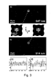
- Fig. 3 illustrates alternating excitation scanning of surface immobilized beads captured using an apparatus according to an exemplary embodiment of the invention.
- Fig. 4 illustrates alternating excitation scanning of mobile fluorescence streptavidin captured using an apparatus according to an exemplary embodiment of the invention.
- Fig. 5 illustrates alternating excitation scanning of fluorescence labeled cells captured using an apparatus according to an exemplary embodiment of the invention.
- Fig. 6 illustrates a focus hold system according to another aspect of the invention.
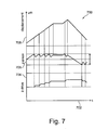
- Fig. 7 illustrates a time dependency of different spatial parameters of the system of Fig. 6 .
- Fig. 1 shows an apparatus 100 for single particle detection according to an exemplary embodiment of the invention.
- the apparatus 100 comprises a readout unit 102 which can also be denoted as a control unit (for instance a CPU, central processing unit, or a microprocessor).
- the readout unit 102 is adapted for controlling the entire operation of the apparatus 100 and is particularly adapted to use alternating excitation schemes for excitation of particles of the sample 104 to obtain, essentially at the same time, two complementary pieces of information regarding the sample 104, thereby broadening the basis of information based on which an evaluation of the experiment can be carried out.
- the apparatus 100 comprises an illumination unit 106 which is in the present embodiment a laser capable of emitting two different wavelengths, namely ⁇ 1 and ⁇ 2 . Furthermore, an xy table 108 on which the sample 104 is mounted can be moved in a two-dimensional manner as indicated schematically by arrows. An xy motor 110 drives the xy table 108.
- the illumination unit 106 is arranged to illuminate the sample 104 mounted on the carrier 108.
- the scanning unit 110 is adapted to scan the sample or two portions of the sample 104 to capture two images thereof, in particularly of the same region of the sample 104.
- the two images may be quasi-simultaneously recorded images, i.e. two samples captured with a time distance which is sufficiently short as compared with motion times of components of the sample 104. For example, a time interval between subsequently captured images may be 5 ms.
- the readout unit 102 may be adapted to control the illumination unit 106 to alternatively excite the sample 104 by irradiating the sample 104 alternatingly with light pulses of the two different wavelengths ⁇ 1 and ⁇ 2 which may differ by more than 100 nm to thereby to activate different fluorescence responses of the sample 104.
- a CCD detector 112 is provided to detect light or electromagnetic radiation of other wavelength regions (for instance UV light or infrared light) impinging on the detector pixels of the CCD detector 112 in response to an illumination of the sample 104 by the two wavelengths laser unit 106.
- other wavelength regions for instance UV light or infrared light
- the scanning unit 110 may move the carrier 108 two-dimensionally and relative to the spatially fixed illumination unit 106 (also the detector 112 is spatially fixed), to thereby obtain an image of the surface of the sample 104.
- the readout unit 102 is further bidirectionally coupled with an input/output unit 114 which is a user interface.
- the input/output unit 114 may comprise input elements such as a keypad, buttons, a joystick or the like to enable a user to supply the system 100 with control commands for defining the experiment to be carried out by the apparatus 100.
- the input/output unit 114 may comprise an output unit such as a display, for example a liquid crystal display by means of which the result of the experiment carried out by the apparatus 100 may be indicated to a user.
- FIG. 2 an apparatus 200 for detecting individual cells according to an exemplary embodiment of the invention will be explained.
- the apparatus 200 (see Fig. 2a ) comprises a first laser 202 adapted for illuminating a sample 104 with light of a first wavelength of 647 nm (red light). Furthermore, a second laser 204 is provided adapted for illuminating the sample 104 with green light (wavelength 514 nm).
- a respective shutter 206 is assigned to each one of the lasers 202, 204 to selectively enable or disable an illumination of the sample 104.
- An acoustic optic modulator (AOM) 208 is provided for each of the laser beams 202, 204 which can be a member that varies amplitude and/or phase of a light beam of the respective laser 202, 204 to control the illumination properties of the sample 104.
- a plurality of lenses 210 are provided in each of the beam paths. Dichroic mirrors 212 may direct light from the two lasers 202, 204 towards the same portion of the sample.
- a further dichroic mirror 214 is located close to an epimicroscope 216. At the epimicroscope 215, the sample 104 is mounted on an xy stage 108.
- the detailed view of the sample 104 on the right-hand of Fig. 2 shows the sample 104 moving over an objective.
- a red scan line 216 is shown yielding red (strip-based) images 218.
- a green scan line 220 is shown yielding green (strip-based) images 222.
- the individual molecules 224 can be identified.
- the images 218, 222 are captured by the line camera 112 which is a CCD camera in the present embodiment.
- the capturing of the strips 218, 222 may take a time of, for instance, seconds to minutes.
- the system 200 switches between red and green by alternatingly activating the lasers 202, 204. This switching may be significantly faster than the switching from one stripe pair 218, 222 to the parallel next stripe pair 218, 222 so that the capturing of each pixel can be performed in red and in green essentially simultaneously so that the results are directly comparable.
- a large two-dimensional image of the sample 104 can be derived in two (or more) color channels.
- FIG. 250 an illumination and detecting sequence can be seen according to which the lasers 202, 204 illuminate the sample 104 and according to which the detector 112 detects the images 218, 222.
- a first diagram 260 shows the ON and OFF times of the acoustic optic modulator 208 related to the red laser 202.
- On a second diagram 270 the operation of the acoustic optic modulator 208 assigned to the green laser 204 is shown.
- the capturing times of the camera 112 can be taken from a third diagram 280. Thus, both excitation and detection can be performed in a pulsed manner.
- the reader system 200 may be set up on a conventional inverted epifluorescence microscope 215 (Axiovert 200M, Zeiss, Germany).
- Samples 104 may be mounted on a high precision scanning stage 108 (SCAN IM, 120x100,March Reviews, Germany) and illuminated through the epi-port of the microscope 215 by 514nm and 647nm laser light from an Ar + -and Kr + -Laser 202, 204 (I-306, I-301; Coherent, USA), respectively.
- Precise illumination timings may be set by acousto-optic modulators 208 (AOMs; 1205C-2/232A-1, Isomet, USA).
- Illumination timing protocols may be generated on a standard personal computer with a LabView-program (National Instruments, USA) and output through an analog/digital IO-card (PCI-6713, National Instruments, USA) to control the AOMs 208 and to trigger the camera 112.
- LabView-program National Instruments, USA
- PCI-6713 National Instruments, USA
- Fig. 2 thus shows the optical paths for the individual colors.
- Precise excitation timings may be achieved using AOMs 208 for each color.
- the timing protocol shows the sequence of interlaced control and trigger signals for the alternating excitation scheme.
- the control signals 260, 270 for the AOMs 208 define the illumination time for each line (t ill ), while the camera trigger 280 starts the preprogrammed acquisition process on the camera 112.
- the delay between two consecutive illuminations, t delay is limited by the readout rate of the camera 112.
- the obtained line recordings are finally assembled into two images 218, 222 corresponding to the two color channels.
- the sample 104 may be continuously shifted through a narrow illumination stripe with a Gaussian intensity profile of 2 ⁇ m full width at half maximum (FWHM) in scanning direction; in the perpendicular direction, the beam may be defocused such that intensity variations were less than 25%.
- a field-stop may be introduced in order to restrict the excitation to the field of view imaged on the chip, thereby preventing photobleaching of adjacent areas during a scan.
- An excitation power of ⁇ 11kW/cm 2 (647nm) and ⁇ 8.8kW/cm 2 (514nm) may be applied (maximum of the Gaussian profile).
- the collected fluorescence may be continuously read-out on a line-camera 112.
- a conventional CCD camera 112 may be used, and the virtual chip size may be reduced to one line.
- the system may be operated at maximum speed.
- the individual lines may be finally assembled into two images 218, 222 corresponding to the two excitation colors.
- Fig. 3 shows the result of an alternating excitation scanning of surface-immobilized beads.
- Fig. 3a and Fig. 3b show scans of 400 ⁇ m x 200 ⁇ m sample area. Individual peaks corresponding to single beads can be easily resolved in both color channels recorded at 514nm (a) and 647nm (b) excitation, as exemplified in the zooms of one particular bead. 58 individual peaks were analyzed by fitting with a Gaussian profile, revealing information about the overall brightness, width and the position of the beads.
- the dye load is distributed highly unequally over the 100nm sphere.
- Streptavidin double-labeled with Cy3 and Cy5 were used as probe; spectrometric analysis revealed a dye to protein ratio of 0.1 for Cy5 and 4.8 for Cy3.
- the bilayer was incubated for 10 minutes with 25nM fluorescent streptavidin, and subsequently washed extensively in Phosphate Buffered Saline (Dulbecco's PBS, Paa, Austria), yielding a surface density of less than 1 streptavidin molecule per ⁇ m 2 .
- the low dye-load in the red channel ensured that the majority of observed streptavidin molecules was labeled with only one Cy5 molecule. As expected for the chosen parameter settings, single molecules can be clearly resolved (see Fig. 4 ).
- Fig. 4 illustrates alternating excitation scanning of mobile fluorescent streptavidin.
- Streptavidin was labeled with Cy3 and Cy5 and bound to a fluid POPC bilayer doped with Biotin-DHPE.
- Rows a) and b) of Fig. 4 show a single streptavidin molecule in the two excitation channels, which was fitted by a Gaussian function, yielding its position (indicated by black cross). Even for these rapidly diffusing molecules the average virtual distance of the peaks recorded in the two color channels was only 80nm (140nm) in x (y) direction, which is a consequence of the interlaced excitation scheme.
- the reduced distance is a consequence of the interlaced recording scheme for the two colors, which renders the single molecule paths not independent between the red and green illumination.
- the scenario is equivalent to imaging a trajectory fragmented into N segments, with adjacent fragments alternately assigned to two images.
- the distance scales approximately with N-2, as confirmed by Monte Carlo simulations (not shown).
- the apparent simultaneity can therefore be improved by reducing the pixel size or increasing t rec , however, at the expense of reduced signal brightness or distorted signal profiles, respectively.
- Fig. 5 shows alternating excitation scanning of fluorescence labeled cells.
- CHO cells were transfected with EYFP-CD147 and labeled with Alexa 647-Fab to CD147.
- the two color channels of the scan (400 ⁇ m x 200 ⁇ m) are shown in Fig. 5a and Fig. 5c for 647nm excitation, and Fig. 5b and Fig. 5d for 514nm excitation.
- Fig. 5a and Fig. 5c for 647nm excitation
- Fig. 5b and Fig. 5d for 514nm excitation.
- clear colocalization of the EYFP-CD147 and its specific antibody is visible (for better visibility, the color map was changed in the magnifications).
- CHO-K1 cells transfected with EYFP-CD147 were used.
- the fusion construct was localized in the plasma membrane and in vesicles, which were transported actively through the cytosol.
- Cells were co-stained with a Fab-fragment of a CD147 antibody (MEM 6/1) fluorescently labeled with AlexaFluor 647 (Molecular Probes, USA).
- MEM 6/1 fluorescently labeled with AlexaFluor 647
- the details show the expected colocalization of the two color channels, thereby demonstrating the interaction of the red-labeled antibody with its green-labeled receptor.
- This proof-of principle experiment indicates the feasibility of the presented screening approach for detecting molecular colocalization in a live cell context.
- the quasi simultaneous imaging approach allows for singling out rare events - for instance the formation of cell-cell contacts -, which are difficult to follow in conventional two-color microscopy.
- the described system represents a valuable extension to multi-color microscopy on biological samples. It provides imaging equivalent of flow cytometry: while multiple wavelength imaging in emission is well established, the implementation of quasi-simultaneous two-color imaging in excitation is provided according to an exemplary embodiment of the invention. Further extension to even more excitation wavelengths, and combination with discrete emission channels for a multi-parameter screening platform is made possible.
- Fig. 6 shows an apparatus 600 as an example for a focus hold system according to another exemplary embodiment of the invention.
- Fig. 6 shows a medium 602 (such as a sample) on a glass slide 604 (for instance a sample carrier).
- An immersion oil structure is denoted with reference numeral 606.
- An objective lens 608 is provided to transport an image via a z-piezo drive 610 and a motor z-drive 612.
- a laser beam 614 generated by a laser source 616 is directed to the medium 602, is reflected there and is supplied to a two segment photodiode 618.
- the two segment photodiode 618 supplies an error signal 620 to a signal conditioner and PID (Proportional Integrated Differential) controller 622 which in turn forwards a control signal to a window discriminator and debouncer 624.
- a step correction signal 626 is supplied to the motor z-drive 612, and the signal conditioner and PID controller 622 supplies an analog correction signal 628 to the z-piezo drive 610.
- the occurrence of a change of the distance of the medium 602/glass 604 relative to the objective 608 may result in a beam distortion of the total reflected laser beam on the two segment photodiode 618.
- An error proportional current signal may be converted in a voltage, may be filtered and may be supplied to the PID regulator 622.
- the PID regulator 622 may control the piezo drive 610 which can carry out fast analog corrections in the kHz (for instance corresponding to microseconds) domain.
- the window discriminator 624 may monitor the error signal and may carry out a slow stepwise raw correction of the piezo zero position via the z-drive 612 integrated in the microscope, when an adjustable threshold value is exceeded.
- the motion may be carried out using a trapezoidal velocity profile and with a maximum rate limited in such a manner that the piezo 610 can be counter-regulated simultaneously, to thereby maintain the sample 602 in the focus.
- it may still be necessary or advantageous to perform region monitoring which can also be integrated in this stage.
- Fig. 7 shows a diagram 700 describing the operation of the device 600.
- abscissa 702 the time is plotted.
- a first ordinate 704 the operation of the z-drive 612 is shown.
- a second ordinate 706 operation of the z-piezo 610 is shown.
- a third coordinate 708 the displacement is shown in micrometers.
Landscapes
- Engineering & Computer Science (AREA)
- Health & Medical Sciences (AREA)
- Physics & Mathematics (AREA)
- Life Sciences & Earth Sciences (AREA)
- General Health & Medical Sciences (AREA)
- General Physics & Mathematics (AREA)
- Multimedia (AREA)
- Molecular Biology (AREA)
- Biomedical Technology (AREA)
- Theoretical Computer Science (AREA)
- Nuclear Medicine, Radiotherapy & Molecular Imaging (AREA)
- Chemical & Material Sciences (AREA)
- Analytical Chemistry (AREA)
- Biochemistry (AREA)
- Immunology (AREA)
- Pathology (AREA)
- Investigating, Analyzing Materials By Fluorescence Or Luminescence (AREA)
Applications Claiming Priority (1)
| Application Number | Priority Date | Filing Date | Title |
|---|---|---|---|
| US98982807P | 2007-11-22 | 2007-11-22 |
Publications (2)
| Publication Number | Publication Date |
|---|---|
| EP2063257A2 true EP2063257A2 (fr) | 2009-05-27 |
| EP2063257A3 EP2063257A3 (fr) | 2010-02-10 |
Family
ID=40409776
Family Applications (1)
| Application Number | Title | Priority Date | Filing Date |
|---|---|---|---|
| EP08002686A Withdrawn EP2063257A3 (fr) | 2007-11-22 | 2008-02-13 | Détection de particule simple à l'aide de schémas d'excitation alternative |
Country Status (1)
| Country | Link |
|---|---|
| EP (1) | EP2063257A3 (fr) |
Cited By (10)
| Publication number | Priority date | Publication date | Assignee | Title |
|---|---|---|---|---|
| WO2010077205A1 (fr) * | 2009-01-05 | 2010-07-08 | Ge Healthcare Bio-Sciences Corp | Système et procédé pour obtenir simultanément une pluralité d'images dans un système d'imagerie |
| FR2944104A1 (fr) * | 2009-08-25 | 2010-10-08 | Commissariat Energie Atomique | Extinction de l'autofluorescence des tissus biologiques en tomographie resolue en temps |
| US7977650B2 (en) | 2006-08-02 | 2011-07-12 | Commissariat A L'energie Atomique | Method and device for 3D reconstruction of the distribution of fluorescent elements |
| US8193518B2 (en) | 2009-09-24 | 2012-06-05 | Commissariat à l'énergie atomique et aux énergies alternatives | Device and method for spatial reconstructing of fluorescence mapping |
| CN102590638A (zh) * | 2012-02-20 | 2012-07-18 | 哈尔滨工业大学 | 数字式深空单粒子探测器及探测方法 |
| CN102713569A (zh) * | 2010-01-28 | 2012-10-03 | 霍夫曼-拉罗奇有限公司 | 尤其是用于血糖确定的测量系统和测量方法 |
| US8847175B2 (en) | 2010-12-15 | 2014-09-30 | Commissariat A L'energie Atomique Et Aux Energies Alternatives | Method for locating an optical marker in a diffusing medium |
| US9036970B2 (en) | 2009-10-08 | 2015-05-19 | Commissariat A L'energie Atomique Et Aux Energies Alternatives | Method and device for diffuse excitation in imaging |
| CN107833511A (zh) * | 2017-11-15 | 2018-03-23 | 中国工程物理研究院电子工程研究所 | 一种优化集成式双光路激光电离效应模拟系统 |
| CN107886820A (zh) * | 2017-11-15 | 2018-04-06 | 中国工程物理研究院电子工程研究所 | 一种集成式双光路激光电离效应模拟系统 |
Citations (1)
| Publication number | Priority date | Publication date | Assignee | Title |
|---|---|---|---|---|
| WO2006066286A1 (fr) | 2004-12-23 | 2006-06-29 | Upper Austrian Research Gmbh | Dispositif d'examen microscopique d'echantillons |
Family Cites Families (1)
| Publication number | Priority date | Publication date | Assignee | Title |
|---|---|---|---|---|
| US7456954B2 (en) * | 2003-06-20 | 2008-11-25 | The Regents Of The University Of California | Modulated excitation fluorescence analysis |
-
2008
- 2008-02-13 EP EP08002686A patent/EP2063257A3/fr not_active Withdrawn
Patent Citations (1)
| Publication number | Priority date | Publication date | Assignee | Title |
|---|---|---|---|---|
| WO2006066286A1 (fr) | 2004-12-23 | 2006-06-29 | Upper Austrian Research Gmbh | Dispositif d'examen microscopique d'echantillons |
Non-Patent Citations (23)
| Title |
|---|
| CAI, L.; FRIEDMAN, N.; XIE, X. S., NATURE, vol. 440, 2006, pages 358 - 62 |
| HEISE, B.; SONNLEITNER, A.; KLEMENT, E. P., MICROSC RES TECH, vol. 66, 2005, pages 312 - 20 |
| HELLER, M. J., ANNU REV BIOMED ENG, vol. 4, 2002, pages 129 - 53 |
| HESSE, J. ET AL., ANAL CHEM, vol. 76, 2004, pages 5960 - 4 |
| HESSE, J. ET AL., GENOME RES, vol. 16, 2006, pages 1041 - 5 |
| HUH, W. K. ET AL., NATURE, vol. 425, 2003, pages 686 - 91 |
| KALB, E.; FREY, S.; TAMM, L. K., BIOCHIM BIOPHYS ACTA, vol. 1103, 1992, pages 307 - 16 |
| KAPANIDIS, A. N. ET AL., PROC NATL ACAD SCI USA., 2004 |
| KAPANIDIS, A. N. ET AL., SCIENCE, vol. 314, 2006, pages 1144 - 7 |
| KENWORTHY, A. K. ET AL., J CELL BIOL, vol. 165, 2004, pages 735 - 46 |
| KURAL, C. ET AL., SCIENCE, vol. 308, 2005, pages 1469 - 72 |
| LEE, N. K. ET AL., BIOPHYS J, vol. 92, 2007, pages 303 - 12 |
| MIR, K. U., GENOME RES, vol. 16, 2006, pages 1195 - 7 |
| MOERTELMAIER, M. A. ET AL., SINGLE MOL., vol. 3, 2002, pages 225 - 231 |
| MOERTELMAIER, M. ET AL., APPL PHYS LETT, vol. 87, 2005, pages 263903 |
| MULLER, B. K. ET AL., BIOPHYS J, vol. 89, 2005, pages 3508 - 22 |
| ROSS, J. ET AL., J PHYS CHEM B, vol. 111, 2007, pages 321 - 6 |
| SAUTER, G.; SIMON, R.; HILLAN, K., NAT REV DRUG DISCOV, vol. 2, 2003, pages 962 - 72 |
| TERUEL, M. N.; MEYER, T., SCIENCE, vol. 295, 2002, pages 1910 - 2 |
| THOMPSON, R. E.; LARSON, D. R.; WEBB, W. W., BIOPHYS J, vol. 82, 2002, pages 2775 - 83 |
| WIESER, S. ET AL., BIOPHYS J, vol. 92, 2007, pages 3719 - 28 |
| YU, J. ET AL., SCIENCE, vol. 311, 2006, pages 1600 - 3 |
| ZHU, J. ET AL., SCIENCE, vol. 301, 2003, pages 836 - 8 |
Cited By (14)
| Publication number | Priority date | Publication date | Assignee | Title |
|---|---|---|---|---|
| US7977650B2 (en) | 2006-08-02 | 2011-07-12 | Commissariat A L'energie Atomique | Method and device for 3D reconstruction of the distribution of fluorescent elements |
| WO2010077205A1 (fr) * | 2009-01-05 | 2010-07-08 | Ge Healthcare Bio-Sciences Corp | Système et procédé pour obtenir simultanément une pluralité d'images dans un système d'imagerie |
| FR2944104A1 (fr) * | 2009-08-25 | 2010-10-08 | Commissariat Energie Atomique | Extinction de l'autofluorescence des tissus biologiques en tomographie resolue en temps |
| US8253116B1 (en) | 2009-09-24 | 2012-08-28 | Commissariat à l'énergie atomique et aux énergies alternatives | Device and method for spatial reconstructing of absorbers mapping |
| US8193518B2 (en) | 2009-09-24 | 2012-06-05 | Commissariat à l'énergie atomique et aux énergies alternatives | Device and method for spatial reconstructing of fluorescence mapping |
| US9036970B2 (en) | 2009-10-08 | 2015-05-19 | Commissariat A L'energie Atomique Et Aux Energies Alternatives | Method and device for diffuse excitation in imaging |
| CN102713569A (zh) * | 2010-01-28 | 2012-10-03 | 霍夫曼-拉罗奇有限公司 | 尤其是用于血糖确定的测量系统和测量方法 |
| CN102713569B (zh) * | 2010-01-28 | 2014-12-31 | 霍夫曼-拉罗奇有限公司 | 尤其是用于血糖确定的测量系统和测量方法 |
| US8847175B2 (en) | 2010-12-15 | 2014-09-30 | Commissariat A L'energie Atomique Et Aux Energies Alternatives | Method for locating an optical marker in a diffusing medium |
| CN102590638A (zh) * | 2012-02-20 | 2012-07-18 | 哈尔滨工业大学 | 数字式深空单粒子探测器及探测方法 |
| CN107833511A (zh) * | 2017-11-15 | 2018-03-23 | 中国工程物理研究院电子工程研究所 | 一种优化集成式双光路激光电离效应模拟系统 |
| CN107886820A (zh) * | 2017-11-15 | 2018-04-06 | 中国工程物理研究院电子工程研究所 | 一种集成式双光路激光电离效应模拟系统 |
| CN107886820B (zh) * | 2017-11-15 | 2023-11-24 | 中国工程物理研究院电子工程研究所 | 一种集成式双光路激光电离效应模拟系统 |
| CN107833511B (zh) * | 2017-11-15 | 2023-11-24 | 中国工程物理研究院电子工程研究所 | 一种优化集成式双光路激光电离效应模拟系统 |
Also Published As
| Publication number | Publication date |
|---|---|
| EP2063257A3 (fr) | 2010-02-10 |
Similar Documents
| Publication | Publication Date | Title |
|---|---|---|
| EP2063257A2 (fr) | Détection de particule simple à l'aide de schémas d'excitation alternative | |
| Bates et al. | Stochastic optical reconstruction microscopy (STORM): a method for superresolution fluorescence imaging | |
| JP6291842B2 (ja) | 検出方法、マイクロアレイの解析方法および蛍光読取装置 | |
| CN102803930B (zh) | 具有聚焦光学器件的光生物传感器 | |
| CN101013136B (zh) | 激光诱导荧光共聚焦扫描装置和方法 | |
| JP2010517056A (ja) | 時間分解蛍光イメージングシステム | |
| US20080099667A1 (en) | Methods and apparatus for sensing a physical substance | |
| JP6422864B2 (ja) | マルチスケールスペクトルナノスコピー | |
| WO2007113473A1 (fr) | Microscopie confocale à réseau bidimensionnel de diodes électroluminescentes | |
| WO2003016781A2 (fr) | Systeme d'eclairage ameliore par plasmons de surface | |
| CA2669999A1 (fr) | Rapide caracterisation thermo-optique de particules | |
| WO2004001402A1 (fr) | Analyseur de biomolecules | |
| WO2008115948A2 (fr) | Procédure de sélection positive pour sélection optiquement dirigée de cellules | |
| García-Sáez et al. | Surface analysis of membrane dynamics | |
| KR20220074886A (ko) | 초고해상도 이미징을 위한 고속 스캐닝 시스템 | |
| CN116670492A (zh) | 用于记录样本中单个粒子的轨迹的方法和显微镜 | |
| EP3654018B1 (fr) | Dispositif d'observation d'échantillon et procédé d'observation d'échantillon | |
| US20070160175A1 (en) | Systems and methods for force-fluorescence microscopy | |
| WO2008010120A2 (fr) | Balayage d'un faisceau appliqué à la détection optique | |
| EP3654019B1 (fr) | Dispositif d'observation d'échantillon et procédé d'observation d'échantillon | |
| JP2004361087A (ja) | 生体分子解析装置 | |
| CN101324527A (zh) | 全反射式激光诱导荧光共聚焦扫描装置及方法 | |
| CN101903761B (zh) | 检测系统和方法 | |
| CA2614254C (fr) | Procede et appareil d'observation de position en trois dimensions | |
| JP2004354345A (ja) | 生体分子解析装置 |
Legal Events
| Date | Code | Title | Description |
|---|---|---|---|
| PUAI | Public reference made under article 153(3) epc to a published international application that has entered the european phase |
Free format text: ORIGINAL CODE: 0009012 |
|
| AK | Designated contracting states |
Kind code of ref document: A2 Designated state(s): AT BE BG CH CY CZ DE DK EE ES FI FR GB GR HR HU IE IS IT LI LT LU LV MC MT NL NO PL PT RO SE SI SK TR |
|
| AX | Request for extension of the european patent |
Extension state: AL BA MK RS |
|
| PUAL | Search report despatched |
Free format text: ORIGINAL CODE: 0009013 |
|
| RIC1 | Information provided on ipc code assigned before grant |
Ipc: G01J 3/44 20060101ALI20091228BHEP Ipc: G01N 21/64 20060101AFI20090312BHEP |
|
| AK | Designated contracting states |
Kind code of ref document: A3 Designated state(s): AT BE BG CH CY CZ DE DK EE ES FI FR GB GR HR HU IE IS IT LI LT LU LV MC MT NL NO PL PT RO SE SI SK TR |
|
| AX | Request for extension of the european patent |
Extension state: AL BA MK RS |
|
| AKY | No designation fees paid | ||
| STAA | Information on the status of an ep patent application or granted ep patent |
Free format text: STATUS: THE APPLICATION IS DEEMED TO BE WITHDRAWN |
|
| 18D | Application deemed to be withdrawn |
Effective date: 20100811 |
|
| REG | Reference to a national code |
Ref country code: DE Ref legal event code: 8566 |