EP2063323A2 - Dispositif d'impression, procédé d'impression et système d'impression - Google Patents
Dispositif d'impression, procédé d'impression et système d'impression Download PDFInfo
- Publication number
- EP2063323A2 EP2063323A2 EP08253370A EP08253370A EP2063323A2 EP 2063323 A2 EP2063323 A2 EP 2063323A2 EP 08253370 A EP08253370 A EP 08253370A EP 08253370 A EP08253370 A EP 08253370A EP 2063323 A2 EP2063323 A2 EP 2063323A2
- Authority
- EP
- European Patent Office
- Prior art keywords
- printing
- sheet
- adhesion amount
- unit
- Prior art date
- Legal status (The legal status is an assumption and is not a legal conclusion. Google has not performed a legal analysis and makes no representation as to the accuracy of the status listed.)
- Granted
Links
Images


Classifications
-
- G—PHYSICS
- G03—PHOTOGRAPHY; CINEMATOGRAPHY; ANALOGOUS TECHNIQUES USING WAVES OTHER THAN OPTICAL WAVES; ELECTROGRAPHY; HOLOGRAPHY
- G03G—ELECTROGRAPHY; ELECTROPHOTOGRAPHY; MAGNETOGRAPHY
- G03G15/00—Apparatus for electrographic processes using a charge pattern
- G03G15/55—Self-diagnostics; Malfunction or lifetime display
- G03G15/553—Monitoring or warning means for exhaustion or lifetime end of consumables, e.g. indication of insufficient copy sheet quantity for a job
- G03G15/556—Monitoring or warning means for exhaustion or lifetime end of consumables, e.g. indication of insufficient copy sheet quantity for a job for toner consumption, e.g. pixel counting, toner coverage detection or toner density measurement
-
- G—PHYSICS
- G03—PHOTOGRAPHY; CINEMATOGRAPHY; ANALOGOUS TECHNIQUES USING WAVES OTHER THAN OPTICAL WAVES; ELECTROGRAPHY; HOLOGRAPHY
- G03G—ELECTROGRAPHY; ELECTROPHOTOGRAPHY; MAGNETOGRAPHY
- G03G15/00—Apparatus for electrographic processes using a charge pattern
- G03G15/36—Editing, i.e. producing a composite image by copying one or more original images or parts thereof
-
- G—PHYSICS
- G03—PHOTOGRAPHY; CINEMATOGRAPHY; ANALOGOUS TECHNIQUES USING WAVES OTHER THAN OPTICAL WAVES; ELECTROGRAPHY; HOLOGRAPHY
- G03G—ELECTROGRAPHY; ELECTROPHOTOGRAPHY; MAGNETOGRAPHY
- G03G15/00—Apparatus for electrographic processes using a charge pattern
- G03G15/50—Machine control of apparatus for electrographic processes using a charge pattern, e.g. regulating differents parts of the machine, multimode copiers, microprocessor control
- G03G15/5025—Machine control of apparatus for electrographic processes using a charge pattern, e.g. regulating differents parts of the machine, multimode copiers, microprocessor control by measuring the original characteristics, e.g. contrast, density
-
- G—PHYSICS
- G03—PHOTOGRAPHY; CINEMATOGRAPHY; ANALOGOUS TECHNIQUES USING WAVES OTHER THAN OPTICAL WAVES; ELECTROGRAPHY; HOLOGRAPHY
- G03G—ELECTROGRAPHY; ELECTROPHOTOGRAPHY; MAGNETOGRAPHY
- G03G15/00—Apparatus for electrographic processes using a charge pattern
- G03G15/55—Self-diagnostics; Malfunction or lifetime display
-
- H—ELECTRICITY
- H04—ELECTRIC COMMUNICATION TECHNIQUE
- H04N—PICTORIAL COMMUNICATION, e.g. TELEVISION
- H04N1/00—Scanning, transmission or reproduction of documents or the like, e.g. facsimile transmission; Details thereof
- H04N1/00567—Handling of original or reproduction media, e.g. cutting, separating, stacking
- H04N1/0057—Conveying sheets before or after scanning
- H04N1/00572—Conveying sheets before or after scanning with refeeding for double-sided scanning, e.g. using one scanning head for both sides of a sheet
- H04N1/00575—Inverting the sheet prior to refeeding
- H04N1/0058—Inverting the sheet prior to refeeding using at least one dead-end path, e.g. using a sheet ejection path
-
- H—ELECTRICITY
- H04—ELECTRIC COMMUNICATION TECHNIQUE
- H04N—PICTORIAL COMMUNICATION, e.g. TELEVISION
- H04N1/00—Scanning, transmission or reproduction of documents or the like, e.g. facsimile transmission; Details thereof
- H04N1/00567—Handling of original or reproduction media, e.g. cutting, separating, stacking
- H04N1/0057—Conveying sheets before or after scanning
- H04N1/00588—Conveying sheets before or after scanning to the scanning position
-
- H—ELECTRICITY
- H04—ELECTRIC COMMUNICATION TECHNIQUE
- H04N—PICTORIAL COMMUNICATION, e.g. TELEVISION
- H04N1/00—Scanning, transmission or reproduction of documents or the like, e.g. facsimile transmission; Details thereof
- H04N1/00567—Handling of original or reproduction media, e.g. cutting, separating, stacking
- H04N1/0057—Conveying sheets before or after scanning
- H04N1/00591—Conveying sheets before or after scanning from the scanning position
-
- H—ELECTRICITY
- H04—ELECTRIC COMMUNICATION TECHNIQUE
- H04N—PICTORIAL COMMUNICATION, e.g. TELEVISION
- H04N1/00—Scanning, transmission or reproduction of documents or the like, e.g. facsimile transmission; Details thereof
- H04N1/00567—Handling of original or reproduction media, e.g. cutting, separating, stacking
- H04N1/0057—Conveying sheets before or after scanning
- H04N1/00599—Using specific components
- H04N1/00602—Feed rollers
-
- H—ELECTRICITY
- H04—ELECTRIC COMMUNICATION TECHNIQUE
- H04N—PICTORIAL COMMUNICATION, e.g. TELEVISION
- H04N1/00—Scanning, transmission or reproduction of documents or the like, e.g. facsimile transmission; Details thereof
- H04N1/00567—Handling of original or reproduction media, e.g. cutting, separating, stacking
- H04N1/0057—Conveying sheets before or after scanning
- H04N1/00599—Using specific components
- H04N1/00615—Guiding elements, e.g. plates
-
- H—ELECTRICITY
- H04—ELECTRIC COMMUNICATION TECHNIQUE
- H04N—PICTORIAL COMMUNICATION, e.g. TELEVISION
- H04N1/00—Scanning, transmission or reproduction of documents or the like, e.g. facsimile transmission; Details thereof
- H04N1/00567—Handling of original or reproduction media, e.g. cutting, separating, stacking
- H04N1/0062—Removing sheets from a stack or inputting media
-
- H—ELECTRICITY
- H04—ELECTRIC COMMUNICATION TECHNIQUE
- H04N—PICTORIAL COMMUNICATION, e.g. TELEVISION
- H04N1/00—Scanning, transmission or reproduction of documents or the like, e.g. facsimile transmission; Details thereof
- H04N1/00567—Handling of original or reproduction media, e.g. cutting, separating, stacking
- H04N1/00631—Ejecting or stacking
-
- H—ELECTRICITY
- H04—ELECTRIC COMMUNICATION TECHNIQUE
- H04N—PICTORIAL COMMUNICATION, e.g. TELEVISION
- H04N1/00—Scanning, transmission or reproduction of documents or the like, e.g. facsimile transmission; Details thereof
- H04N1/23—Reproducing arrangements
- H04N1/2307—Circuits or arrangements for the control thereof, e.g. using a programmed control device, according to a measured quantity
- H04N1/2338—Circuits or arrangements for the control thereof, e.g. using a programmed control device, according to a measured quantity according to user specified instructions, e.g. user selection of reproduction mode
-
- H—ELECTRICITY
- H04—ELECTRIC COMMUNICATION TECHNIQUE
- H04N—PICTORIAL COMMUNICATION, e.g. TELEVISION
- H04N1/00—Scanning, transmission or reproduction of documents or the like, e.g. facsimile transmission; Details thereof
- H04N1/23—Reproducing arrangements
- H04N1/2307—Circuits or arrangements for the control thereof, e.g. using a programmed control device, according to a measured quantity
- H04N1/2346—Circuits or arrangements for the control thereof, e.g. using a programmed control device, according to a measured quantity according to a detected condition or state of the reproducing device, e.g. temperature or ink quantity
-
- H—ELECTRICITY
- H04—ELECTRIC COMMUNICATION TECHNIQUE
- H04N—PICTORIAL COMMUNICATION, e.g. TELEVISION
- H04N1/00—Scanning, transmission or reproduction of documents or the like, e.g. facsimile transmission; Details thereof
- H04N1/23—Reproducing arrangements
- H04N1/2307—Circuits or arrangements for the control thereof, e.g. using a programmed control device, according to a measured quantity
- H04N1/2369—Selecting a particular reproducing mode from amongst a plurality of modes, e.g. paper saving or normal, or simplex or duplex
-
- H—ELECTRICITY
- H04—ELECTRIC COMMUNICATION TECHNIQUE
- H04N—PICTORIAL COMMUNICATION, e.g. TELEVISION
- H04N1/00—Scanning, transmission or reproduction of documents or the like, e.g. facsimile transmission; Details thereof
- H04N1/23—Reproducing arrangements
- H04N1/29—Reproducing arrangements involving production of an electrostatic intermediate picture
- H04N1/295—Circuits or arrangements for the control thereof, e.g. using a programmed control device, according to a measured quantity
-
- B—PERFORMING OPERATIONS; TRANSPORTING
- B41—PRINTING; LINING MACHINES; TYPEWRITERS; STAMPS
- B41J—TYPEWRITERS; SELECTIVE PRINTING MECHANISMS, i.e. MECHANISMS PRINTING OTHERWISE THAN FROM A FORME; CORRECTION OF TYPOGRAPHICAL ERRORS
- B41J3/00—Typewriters or selective printing or marking mechanisms characterised by the purpose for which they are constructed
- B41J3/60—Typewriters or selective printing or marking mechanisms characterised by the purpose for which they are constructed for printing on both faces of the printing material
-
- G—PHYSICS
- G03—PHOTOGRAPHY; CINEMATOGRAPHY; ANALOGOUS TECHNIQUES USING WAVES OTHER THAN OPTICAL WAVES; ELECTROGRAPHY; HOLOGRAPHY
- G03G—ELECTROGRAPHY; ELECTROPHOTOGRAPHY; MAGNETOGRAPHY
- G03G15/00—Apparatus for electrographic processes using a charge pattern
- G03G15/06—Apparatus for electrographic processes using a charge pattern for developing
- G03G15/065—Arrangements for controlling the potential of the developing electrode
-
- G—PHYSICS
- G03—PHOTOGRAPHY; CINEMATOGRAPHY; ANALOGOUS TECHNIQUES USING WAVES OTHER THAN OPTICAL WAVES; ELECTROGRAPHY; HOLOGRAPHY
- G03G—ELECTROGRAPHY; ELECTROPHOTOGRAPHY; MAGNETOGRAPHY
- G03G2215/00—Apparatus for electrophotographic processes
- G03G2215/00362—Apparatus for electrophotographic processes relating to the copy medium handling
- G03G2215/00535—Stable handling of copy medium
- G03G2215/00556—Control of copy medium feeding
- G03G2215/00578—Composite print mode
- G03G2215/00582—Plural adjacent images on one side
-
- G—PHYSICS
- G03—PHOTOGRAPHY; CINEMATOGRAPHY; ANALOGOUS TECHNIQUES USING WAVES OTHER THAN OPTICAL WAVES; ELECTROGRAPHY; HOLOGRAPHY
- G03G—ELECTROGRAPHY; ELECTROPHOTOGRAPHY; MAGNETOGRAPHY
- G03G2215/00—Apparatus for electrophotographic processes
- G03G2215/00362—Apparatus for electrophotographic processes relating to the copy medium handling
- G03G2215/00535—Stable handling of copy medium
- G03G2215/00556—Control of copy medium feeding
- G03G2215/00586—Control of copy medium feeding duplex mode
Definitions
- the present invention relates to a printing device, a printing method and a printing system for executing printing on a sheet (e.g. paper) according to inputted print data, and in particular, to a printing device, a printing method and a printing system capable of implementing the printing while taking recycling of the printed sheet into account.
- a printing device e.g. paper
- a printing method and a printing system capable of implementing the printing while taking recycling of the printed sheet into account.
- a technique described in Japanese Patent Provisional Publication No. 2001-51555 calculates an adhesion ratio of the print agent on each sheet (area ratio between the print agent (adhering to the sheet) and the sheet) and displaying (printing) information about the recycling of the printed sheet on the sheet based on the calculated adhesion ratio.
- the present invention which has been made in consideration of the above problems, is advantageous in that a printing device and a printing system, capable of executing the printing of print data on a sheet while taking account of the possibility of recycling of the printed sheet even when the print data involves an excessive amount of the print agent adhering to the sheet (excessive adhesion amount) and disables the recycling if the printing is carried out without modification, can be provided.
- a printing device comprising a printing unit which prints an image on a sheet according to a print command, a judgment unit which judges whether a total adhesion amount of a print agent adhering to the sheet for the image printing exceeds a prescribed threshold value or not based on inputted print data, and a control unit which executes a process for reducing the total adhesion amount of the print agent when the total adhesion amount is judged to exceed the threshold value by the judgment unit.
- the process for reducing the total adhesion amount of the print agent is executed by the control unit when the total adhesion amount is judged by the judgment unit to exceed the threshold value based on the print data.
- the printing can be carried out while taking account of the possibility of the recycling, by the reduction of the total adhesion amount of the print agent.
- the judgment unit includes a calculation unit which calculates the total adhesion amount based on the print data.
- the judgment on whether the total adhesion amount exceeds the threshold value or not can be made properly by the judgment unit by use of the total adhesion amount calculated by the calculation unit based on the print data.
- the judgment unit calculates the total adhesion amount based on adhesion ratio of the print agent adhering to the sheet.
- the total adhesion amount of the print agent can be determined with high accuracy based on the adhesion ratio of the print agent adhering to the sheet.
- the "adhesion ratio" of the print agent means area ratio between the print agent (adhering to the sheet) and the sheet, for example.
- control unit executes a process for reducing a dot adhesion amount, as the amount of adhesion of the print agent per dot formed on the sheet for the printing, when the total adhesion amount is judged to exceed the threshold value by the judgment unit.
- the process for reducing the dot adhesion amount (the amount of adhesion of the print agent per dot) is executed by the control unit when the total adhesion amount is judged to exceed the threshold value. Since the number of dots of the printed image is not changed by the process by the control unit, the printing allowing for the recycling of the printed sheet can be carried out with no substantial deterioration of image quality.
- control unit executes a process for reducing the number of dots printed on the sheet when the total adhesion amount is judged to exceed the threshold value by the judgment unit.
- the process for reducing the number of dots printed on the sheet is executed by the control unit when the total adhesion amount is judged to exceed the threshold value.
- the printing unit includes a multiple-page printing unit which prints the print data of multiple pages on one sheet according to a multiple-page print command.
- the control unit executes a process for reducing the number of pages of the print data printed on one sheet when the total adhesion amount is judged to exceed the threshold value by the judgment unit in the image printing according to the multiple-page print command.
- the process for reducing the number of pages of the print data printed on one sheet is executed by the control unit when the total adhesion amount is judged to exceed the threshold value.
- the printing unit includes a single-side printing unit which executes image printing on one side of the sheet according to a single-side print command and a duplex printing unit which executes image printing on both sides of the sheet according to a duplex print command.
- the control unit makes the single-side printing unit execute the image printing on one side of the sheet when the total adhesion amount is judged to exceed the threshold value by the judgment unit in the image printing according to the duplex print command.
- the printing device configured as above, when the total adhesion amount regarding print data of two pages (supposed to be printed on different sides of one sheet, respectively) is judged to exceed the threshold value, the two pages are separately printed on different sheets by the single-side printing unit.
- the reduction of the total adhesion amount (of the print agent adhering to each sheet) can be achieved by simple control.
- the printing device further comprises a setting unit which allows a user to set the threshold value.
- the user is allowed to set the threshold value at a proper value (corresponding to a value which has been specified for the recycling of the sheet) for various sheets made of various materials.
- a proper value corresponding to a value which has been specified for the recycling of the sheet
- the judgment unit makes the judgment on whether the total adhesion amount of the print agent exceeds the threshold value or not in regard to each of the multiple sheets and the control unit executes the process for reducing the total adhesion amount of the print agent in regard to all the multiple sheets based on the judgment by the judgment unit.
- control (reduction) of the total adhesion amount by the control unit can be carried out properly in regard to all the multiple sheets (taking all the multiple sheets into consideration) based on the judgment by the judgment unit in regard to each sheet.
- the printing device further comprises a selection unit which allows a user to select whether or not to make the control unit execute the process for reducing the total adhesion amount of the print agent.
- a printing system comprising an upper-level device which forms print data, a lower-level device which prints an image on a sheet according to the print data formed by the upper-level device, a judgment unit which judges whether a total adhesion amount of a print agent adhering to the sheet for the image printing exceeds a prescribed threshold value or not based on the print data, and a control unit which executes a process for reducing the total adhesion amount of the print agent when the total adhesion amount is judged to exceed the threshold value by the judgment unit.
- the process for reducing the total adhesion amount of the print agent is executed by the control unit when the total adhesion amount is judged by the judgment unit to exceed the threshold value based on the print data.
- the printing can be carried out while taking account of the possibility of the recycling, by the reduction of the total adhesion amount of the print agent.
- the judgment unit and the control unit may either be placed in the upper-level device or in the lower-level device, or properly distributed into the upper-level device and the lower-level device. It is also possible to place the judgment unit and the control unit in a device other than the upper-level device or the lower-level device.
- a printing method for a printing device which prints an image by adhering print agent on a sheet according to inputted print data and an inputted print command, comprising the steps of setting a threshold value of an amount of the print agent per sheet as a prescribed threshold value, calculating a total adhesion amount of the print agent per sheet based on the inputted print data and the inputted print command, judging whether the total adhesion amount of the print agent per sheet exceeds the prescribed threshold value, and reducing the total adhesion amount of the print agent per sheet when the total adhesion amount is judges to exceed the prescribed threshold value.
- the step of reducing may reduce the total adhesion amount of the print agent per sheet by reducing an adhesion amount of the print agent per dot formed on the sheet when the total adhesion amount is judged to exceed the prescribed threshold value.
- the step of reducing may reduce the total adhesion amount of the print agent per sheet by reducing the number of dots printed on the sheet when the total adhesion amount is judged to exceed the prescribed threshold value.
- the step of reducing may reduce the total adhesion amount of the print agent per sheet by reducing a printing area on one sheet when the total adhesion amount is judged to exceed the prescribed threshold value.
- the step of reducing may reduce the total adhesion amount of the print agent per sheet by reducing the number of pages printed on one sheet when the print command includes a command for printing a plurality of pages on one sheet.
- the step of reducing may reduce the total adhesion amount of the print agent per sheet by printing only one side of the sheet.
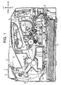
- Fig. 1 is a sectional side view showing the general composition of a printer 1 as an example of a printing device (or a lower-level device in a printing system) in accordance with an embodiment of the present invention.
- a printer 1 as an example of a printing device (or a lower-level device in a printing system) in accordance with an embodiment of the present invention.
- an X-axis is set in the horizontal direction and a Y-axis is set in the vertical direction for convenience of explanation.
- the printing device in accordance with this embodiment is not restricted to a printer; the present invention is applicable also to various other printing devices such as copy machines and MFPs (Multi-Function Peripherals).
- MFPs Multi-Function Peripherals
- the printer 1 executes printing on a sheet 2 (e.g. paper) based on image data received from an upper-level device 55 (personal computer, server, etc.) which will be described later (see Fig. 2 ) or an external storage device 56 (digital camera, USB memory, etc.) which will be described later (see Fig. 2 ).
- a printing system in accordance with an embodiment of the present invention is formed by the printer 1 and the upper-level device 55.
- a sheet feed tray 4 (storing a stack of sheets 2) is contained in the base (-Y side in Fig. 1 ) of the body 3 of the printer 1.
- a first feeding path 5 is formed to feed the sheet 2 (extracted from the sheet feed tray 4) to a print unit 6 and to the outside of the body 3 (output tray 8).
- the print unit 6 and a fixation unit 7 are placed.
- An output tray 8 is formed on the top (+Y side in Fig. 1 ) of the body 3. The sheet 2 after being printed on by the print unit 6 is fed through the first feeding path 5 and ejected to the output tray 8.
- the first feeding path 5 is equipped with a sheet feed roller 9, registration rollers 10 and sheet ejection rollers 11.
- a first feeding unit of the printer 1 is formed by the sheet feed roller 9, the registration rollers 10 and the sheet ejection rollers 11.
- a single-side printing unit, (part of) a multiple-page printing unit and (part of) a printing unit are implemented by the first feeding path 5 (or the first feeding unit), the print unit 6, the fixation unit 7, a CPU 51 (see Fig. 2 ), a ROM 52 (see Fig. 2 ) and a RAM 53 (see Fig. 2 ).
- the CPU 51, the ROM 52 and the RAM 53 will be described later.
- the sheet feed roller 9, the registration rollers 10 and the sheet ejection rollers 11 are rotated by driving force of a motor M (see Fig. 2 ) which is linked with the rollers.
- the sheet feed roller 9 (as a feeding unit), which is placed at the front (+X side) of the sheet feed tray 4, picks up one sheet 2 stored in the sheet feed tray 4 and feeds the sheet 2 toward the registration rollers 10.
- the registration rollers 10, which are placed on the upstream side of the print unit 6, correct the skewing of the sheet 2 and feed the aligned (registered) sheet toward the print unit 6.
- a sheet feed unit is formed by the sheet feed tray 4, the sheet feed roller 9 and the registration rollers 10.
- the sheet ejection rollers 11 (as an ejection unit), which are placed on the downstream side of the print unit 6, eject the sheet 2 to the output tray 8.
- a sheet ejection unit is formed by the sheet ejection rollers 11 and the output tray 8.
- the print unit 6 includes a charging unit 12, a photosensitive drum 13, a scanner unit 14, a toner cartridge 15, toner 16 and a transfer roller 17.
- the print unit 6 forms (prints) an image on the sheet 2 according to inputted image data.
- the toner 16 is used as the print agent in this embodiment, other print agents (e.g. ink) may be used when the print unit 6 is implemented as an inkjet printing unit.
- the charging unit 12 is placed in the vicinity of the photosensitive drum 13.
- the surface of the photosensitive drum 13, after being electrically charged by the charging unit 12, is irradiated with a laser beam emitted and scanned by the scanner unit 14, by which an electrostatic latent image is formed on the drum surface.
- the electrostatic latent image on the photosensitive drum 13 is visualized (developed into a "toner image") by use of the toner 16 supplied from the toner cartridge 15.
- the transfer roller 17 is placed to closely face the photosensitive drum 13.
- the sheet 2 fed from the registration rollers 10 is sandwiched between the photosensitive drum 13 and the transfer roller 17, by which the toner image on the photosensitive drum 13 is transferred to the sheet 2.
- the fixation unit 7 on the downstream side of the photosensitive drum 13 heat-fixes the image which has been transferred to the sheet 2.
- a second feeding path 18 to be used for duplex printing is formed between the first feeding path 5 and the sheet feed tray 4.
- the second feeding path 18 is equipped with relay rollers 19 for feeding the sheet 2.
- the relay rollers 19 are rotated by driving force of the motor M (see Fig. 2 ) which is linked with the rollers.
- a second feeding unit of the printer 1 is formed by the relay rollers 19.
- a duplex printing unit, the multiple-page printing unit and the printing unit are implemented by the single-side printing unit and the second feeding path 18 (or the second feeding unit).
- the front end (+X side in Fig. 1 ) of the second feeding path 18 connects to an upstream part (sheet feed unit's side) of the first feeding path 5 between the sheet feed roller 9 and the registration rollers 10. Meanwhile, the rear end (-X side in Fig. 1 ) of the second feeding path 18 connects to a downstream part (sheet ejection unit's side) of the first feeding path 5 between the fixation unit 7 and the sheet ejection rollers 11.
- a sheet ejection sensor 20 is placed on the upstream side of the sheet ejection rollers 11.
- a reverse sheet feed sensor 21 is placed in an upstream part (-X side in Fig. 1 ) of the second feeding path 18.
- the printer 1 further includes an operation unit 59 (see Fig. 2 ) and a display unit 60 (see Fig. 2 ) as user interfaces.
- the printer 1 is capable of not only the single-side printing (printing on one side of the sheet 2 supplied from the sheet feed tray 4) but also the duplex printing (printing on both sides of the sheet 2).
- printer 1 of this embodiment (equipped with only one toner cartridge 15) is only capable of single-color printing using a single-color toner 16
- this embodiment is applicable also to a color printer which is equipped with multiple toner cartridges 15 in the print unit 6 and capable of multicolor printing using multiple color toners 16 (e.g. yellow, magenta, cyan and black).
- a sheet 2 is picked up from the sheet feed tray 4 and fed to the registration rollers 10 by the sheet feed roller 9.
- the sheet 2 is aligned (registered) and then fed to the print unit 6.
- an image is printed on the sheet 2 by the transfer of the toner image from the photosensitive drum 13.
- the image printed on the sheet 2 is heat-fixed by the fixation unit 7. After the heat fixing, the sheet 2 is ejected to the output tray 8 by the sheet ejection rollers 11, with the printed surface facing downward.
- the printing in the single-side printing process is carried out in the normal order (the pages (image data) are successively printed on the sheets 2 starting from the first page).
- the rotation of the sheet ejection rollers 11 is reversed again (to the normal direction) when the rear end of the sheet 2 is detected by the reverse sheet feed sensor 21.
- the sheet 2 After being fed to the sheet feed unit's side of the first feeding path 5 via the second feeding path 18, the sheet 2 is fed again to the print unit 6.
- the print unit 6 an image is printed on the back (which has not been printed on yet) of the sheet 2.
- the sheet 2 after the duplex printing is ejected to the output tray 8, with the back facing downward, that is, with the front (which was printed on first) facing upward.
- the printer 1 of this embodiment carries out the duplex printing so that the sheets 2 are ejected to the output tray 8 with the first page of the image data (printed on the first sheet) facing downward.
- the duplex printing the front of the sheet 2 is printed on first with the second page (even-numbered page) of the image data, and thereafter the back of the sheet 2 is printed on with the first page (odd-numbered page) of the image data.
- Fig. 2 is a block diagram showing the control configuration of the printer 1.
- the printer 1 is controlled by the control unit 50 (as a unit for calculation, judgment and control) which is implemented by a well-known computer, in which the ROM 52 and the RAM 53 are connected to the CPU 51.
- a print program for the control of a variety of operation/driving of the printer 1, has been stored in the ROM 52. Results of processing, data during processing, etc. are temporarily stored in the RAM 53.
- the print program stored in the ROM 52 is executed by the CPU 51. Incidentally, a normal print program and a recycling print program have been stored in the ROM 52 as the print program.
- the operations of the print unit 6, the fixation unit 7 and the motor M are controlled by the CPU 51 which is connected therewith.
- the sheet feed roller 9, the registration rollers 10, the sheet ejection rollers 11 and the relay rollers 19 are linked with the motor M via unshown gears, and thus the driving of the rollers is also controlled by the CPU 51.
- the upper-level device 55 and the external storage device 56 are detachably connected to the CPU 51 via a network I/F (interface) 61 and an external storage I/F 62, respectively.
- the CPU 51 of the printer 1 can receive image data transmitted from the upper-level device 55 or the external storage device 56.
- connection of the CPU 51 (printer 1) with the upper-level device 55 is not restricted to the connection via the network I/F 61; direct connection using a printer port (USB port, RS232C port, etc.), network connection using a wireless LAN, etc. are also possible.
- the upper-level device 55 is capable of transmitting a print command to the CPU 51 (printer 1) via a printer driver. Being transmitted from the upper-level device 55 together with print data, the print command makes the printer 1 execute the printing of the print data.
- the print data includes image data for the printing of X pages, print mode data specifying a print mode, and print method data specifying a print method.
- the print mode data is data specifying a selection between a normal print mode and a recycling print mode which will be explained later.
- the print method data is data specifying a selection between the single-side printing (printing on one side of the sheet 2) and the duplex printing (printing on both sides of the sheet 2) and a selection on whether "N-in-1 printing" (explained later) should be executed or not.
- the ROM 52 has further stored an adhesion ratio calculation program.
- Bitmap data is generated by the CPU 51 based on the received image data.
- the adhesion ratio calculation program calculates the number C of dots to be printed on the sheet 2, and thereby obtains a toner adhesion area T (total area of the toner adhering to the sheet 2).
- the calculation unit made up of the CPU 51, the ROM 52 and the RAM 53 calculate a total adhesion amount QP (total amount of the toner 16 used) from the number C of dots or the adhesion ratio D. While the control in this embodiment is executed by use of the adhesion ratio D of the toner 16 on the sheet 2, the control may also be carried out using the number C of dots or the total adhesion amount QP.
- the ROM 52 has further stored an adhesion amount control program.
- the adhesion amount control program adjusts development bias of the toner 16, by which a dot adhesion amount QD of the toner 16 adhering to the photosensitive drum 13 is adjusted, by which the total adhesion amount QP of the toner 16 adhering to the sheet 2 (i.e. the dot adhesion amount QD (per dot) ⁇ the number C of dots) is adjusted.
- the control by the adhesion amount control program may be carried out differently.
- the adhesion amount control program may be designed to adjust output voltage of the charging unit 12, by which the amount of electric charge on the photosensitive drum 13 is adjusted, the dot adhesion amount QD of the toner 16 adhering to the photosensitive drum 13 is adjusted, and the total adhesion amount QP of the toner 16 adhering to the sheet 2 (i.e. the dot adhesion amount QD (per dot) ⁇ the number C of dots) is adjusted.
- the adjustment of the total adhesion amount QP may also be made by controlling the intensity (light amount) of the laser of the scanner unit 14. By this method, the electric potential on the surface of the photosensitive drum 13 is adjusted, the dot adhesion amount QD of the toner 16 per dot is controlled, and the total adhesion amount QP of the toner 16 adhering to the sheet 2 is adjusted.
- the adjustment of the total adhesion amount QP of the toner 16 adhering to the sheet 2 may also be made by combining some of the above methods (e.g. by controlling both the number C of dots and the dot adhesion amount QD of the toner 16 per dot).
- the operation unit 59 and the display unit 60 serve as user interfaces in cases where the print command is inputted to the printer 1 by the user.
- the input of the print command by the user through the operation unit 59 is made in a state in which the image data has already been received from the upper-level device 55 or the external storage device 56 and stored in the RAM 53.
- the aforementioned print mode data and print method data are inputted by the user through the operation unit 59 and the printing is executed according to the inputted print mode/method data.
- the print mode and the print method may be specified by not only the upper-level device 55.
- the printer 1 may receive only image data from the upper-level device 55 while letting the user specify the print mode and the print method through the operation unit 59 and the display unit 60.
- the print mode and the print method may also be stored previously in the external storage device 56 storing image data.
- the sheet ejection sensor 20 and the reverse sheet feed sensor 21 are Also connected to the CPU 51.
- the rotational direction of the sheet ejection rollers 11 is controlled by the CPU 51 depending on the detected feeding status.
- the adhesion ratio calculation program and the adhesion amount control program are stored in the ROM 52 of the printer 1 and the units for the calculation, judgment and control (implemented by the control unit 50) are also placed in the printer 1 in the control configuration of Fig. 2
- the configuration of the printing system in accordance with this embodiment is not restricted to that of Fig. 2 .
- the adhesion ratio calculation program and the adhesion amount control program may be stored not in the printer 1 but in the upper-level device 55.
- the calculation unit, judgment unit and control unit may also be placed not in the printer 1 but in the upper-level device 55, or properly distributed into the printer 1 and the upper-level device 55.
- the calculation of the adhesion ratio D and the control of the total adhesion amount QP may also be conducted for color toners 16 (e.g. yellow, magenta, cyan and black). In this case, more refined sorting of printed sheets for the recycling can be realized by carrying out the calculation of the adhesion ratio D and the control of the total adhesion amount QP for each of the color toners 16.
- Figs. 3 - 7 (which are linked together) indicate one process (including several processes described below) which is executed by the control unit 50 (CPU 51) of the printer 1.
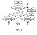
- Fig. 3 is a flow chart showing a print mode/method judgment process which is executed by the CPU 51. First, the print mode/method judgment process will be explained below referring to Fig. 3 .
- the print program (for the process shown in Figs. 3 - 7 ) is carried out by the CPU 51 when the print command is executed due to transmission of print data from the upper-level device 55 to the CPU 51, or when the print command is issued by the upper-level device 55 or by the user through the operation unit 59 of the printer 1 after transmission of print data from the external storage device 56 to the CPU 51.
- the CPU 51 first judges whether the print mode data is recycling print mode data (specifying a recycling print mode) or not (S 1).
- the recycling print mode is a print mode in which the printing on the sheet 2 by the printer 1 is executed according to the recycling print program.
- the CPU 51 executes the normal print program (S2), by which the printing on the sheet 2 is carried out in the normal print mode.
- the normal print mode is a print mode in which the printing is executed simply according to the image data and the setting of the print method data (single-side printing, duplex printing, N-in-1 printing), without considering the possibility of recycling.
- the CPU 51 judges whether the print method data is N-in-1 printing data (specifying N-in-1 printing) or not (S3).
- an "arrangement area" is set up on one side of a sheet 2 so that reduced image data (image data of reduced images) of N pages can be arranged and fit in the area, and then reduced image data of X pages (X ⁇ N) are arranged and printed in the arrangement area.
- an arrangement area in which reduced images of eight pages can be arranged and fit is set up on one side of the sheet 2 and then reduced images of six pages are printed in the arrangement area by the N-in-1 printing (8-in-1 printing).
- the CPU 51 judges whether the print method data is duplex printing data (specifying duplex printing) or not (S4). When negative, that is, when the duplex printing has not been specified (S4: NO), the CPU 51 judges that the print method data is single-side printing data (advances to a process shown in Fig. 4 ).
- the CPU 51 judges that the print method data is duplex printing data (advances to a process shown in Fig. 5 ).
- the CPU 51 judges whether the print method data is duplex printing data or not similarly to S4 (S5). When negative, that is, when the duplex printing has not been specified (S5: NO), the CPU 51 judges that the print method data is single-side N-in-1 printing data (advances to a process shown in Fig. 6 ).
- the CPU 51 judges that the print method data is duplex N-in-1 printing data (advances to a process shown in Fig. 7 ).
- the print mode and the print method in regard to the print command are judged by the CPU 51 by the print mode/method judgment process ( Fig. 3 ) described above.
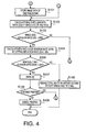
- Fig. 4 is a flow chart of the recycling print program for the single-side printing which is executed by the CPU 51.
- a process according to the recycling print program for the single-side printing i.e. single-side printing process in the recycling mode
- the process of Fig. 4 is executed in the case where the N-in-1 printing has not been specified (S3: NO) and the duplex printing has not been specified (S4: NO) in the process of Fig. 3 .
- the CPU 51 stores image data of one page in the RAM 53 (S101).
- the CPU 51 calculates a single-side adhesion ratio DO of the toner 16 in the single-side printing (S102) by executing the adhesion ratio calculation program (by comparing the toner adhesion area T per page (total area of toner adhering to one side of the sheet 2) with the area P of the sheet 2).
- the toner adhesion area T means the total area of the toner 16 adhering to the sheet 2, which is obtained from the number C of dots of the bitmap data generated from the image data.
- the obtained single-side adhesion ratio DO is stored in the RAM 53 to be used in the subsequent step.
- the area P of the sheet 2 is obtained from its sheet size.
- the CPU 51 judges whether or not the single-side adhesion ratio DO calculated in S 102 is 25 % or more (S103).
- the threshold value regarding the adhesion ratio D (e.g. DO) is set at 25 % in this embodiment assuming a case where a recycling possibility standard, specifying that the recycling of printed sheets into recycled paper is possible when the adhesion ratio D of the printed sheets 2 is less than 25 %, has been presented by a recycling organization.
- the threshold value regarding (to be compared with) the adhesion ratio D should be changed according to the recycling possibility standard when the standard changes.
- the threshold value of the adhesion ratio D may also be set at a proper value by the user through the upper-level device 55 or the operation unit 59 of the printer 1.
- the CPU 51 advances to the step S2 in Fig. 3 and executes the normal print program, by which the printing on one side of the sheet 2 is carried out by the single-side printing unit in the normal print mode.
- the CPU 51 executes a step of recalculating the single-side adhesion ratio DO on the RAM 53 (S104).
- the reduction ratio R is a value which represents the ratio (percentage) of the decrease in the amount of the toner 16 adhering to the sheet 2 which is caused by the execution of the adhesion amount control program.
- the CPU 51 judges whether or not the new single-side adhesion ratio DOR obtained by the recalculation is 25 % or more (S 105).
- DOR is less than 25 % (S105: NO)
- the CPU 51 makes the single-side printing unit execute printing on one side of the sheet 2 in a state in which the total adhesion amount QP of the toner 16 has been reduced by the adhesion amount control program (S106).
- S106 the adhesion amount control program
- the reduction of the total adhesion amount QP of the toner 16 is implemented by a process of subtracting an amount corresponding to the reduction ratio R from the total adhesion amount QP of the toner 16 that should be used in the normal printing.
- the reduction ratio R is set at 30 % in this embodiment since excessive adjustment (reduction ratio R > 30 %) causes an extreme decrease in the total adhesion amount QP of the toner 16 in the actual printing on the sheet 2 (unduly thin printed image) and deterioration of print quality.
- the reduction ratio R does not have to be restricted to 30 % when the printing has to be carried out even with a higher reduction ratio R.
- the reduction ratio R may also be set at a proper value by the user through the upper-level device 55 or the operation unit 59 of the printer 1.
- the CPU 51 advances to the step S2 in Fig. 3 and makes the single-side printing unit execute printing on one side of the sheet 2 according to the normal print program.
- the sheet 2 is made non-recyclable by the printing in this case since the new single-side adhesion ratio DOR is 25 % or more.
- Fig. 5 and Fig. 4 are flow charts of the recycling print program for the duplex printing which is executed by the CPU 51.
- a process according to the recycling print program for the duplex printing i.e. duplex printing process in the recycling mode
- Figs. 3 , 4 and 5 will be described below referring to Figs. 3 , 4 and 5 .
- the process of Fig. 5 is executed in the case where the N-in-1 printing has not been specified (S3: NO) and the duplex printing has been specified (S4: YES) in the process of Fig. 3 .
- the CPU 51 stores image data of two pages in the RAM 53 (S201).
- the CPU 51 calculates a duplex adhesion ratio DB of the toner 16 in the duplex printing (S202) by executing the adhesion ratio calculation program (by comparing the toner adhesion area T on two pages (total area of toner adhering to two sides of the sheet 2) with the area P of the sheet 2).
- the "toner adhesion area T on two pages” means the total area of the toner 16 adhering to the sheet 2 in the duplex printing, which is obtained from the number C of dots of the bitmap data of two pages generated from the image data.
- the obtained duplex adhesion ratio DB is stored in the RAM 53 to be used in the subsequent step.
- the CPU 51 judges whether or not the duplex adhesion ratio DB calculated in S202 is 25 % or more (S203).
- the duplex adhesion ratio DB is less than 25 % (S203: NO)
- the CPU 51 executes the normal print program in the step S2 in Fig. 3 , by which the printing on both sides of the sheet 2 is executed by the duplex printing unit in the normal print mode.
- the CPU 51 executes a step of recalculating the duplex adhesion ratio DB on the RAM 53 (S204).
- the CPU 51 judges whether or not the recalculated duplex adhesion ratio DBR is 25 % or more (S205).
- DBR is less than 25 % (S205: NO)
- the CPU 51 makes the duplex printing unit execute printing on both sides of the sheet 2 in a state in which the total adhesion amount QP of the toner 16 has been reduced by the adhesion amount control program (S206).
- S206 the adhesion amount control program
- the CPU 51 advances to the step S 102 in Fig. 4 and calculates the single-side adhesion ratio DO of the image data of each of the two pages which have been stored in the RAM 53 in S201 by executing the adhesion ratio calculation program. Thereafter, the steps for the single-side printing process (S102 - S108, S2) are executed for each of the two pages.
- the CPU 51 makes the single-side printing unit execute the printing on one side of the sheet 2 in the step S2 in Fig. 3 or in the step S106. Consequently, only one side of the sheet 2 is printed on even though the print method data has been judged to be duplex printing data in S3 - S4 in Fig. 3 .
- Figs. 8A - 8C are schematic diagrams showing a case where single-side printing is carried out for a duplex print command.
- Fig. 8A indicates that the inputted print command is a duplex print command, wherein the character "A" drawn with solid lines represents a print image that should be formed on the front of the sheet 2, while the horizontally inverted character “B” drawn with broken lines represents a print image that should be formed on the back of the sheet 2.
- Figs. 8B and 8C indicate the above case where the image data of two pages (which should be printed on both sides of the sheet 2 as shown in Fig. 8A ) are separately printed on two sheets 2 by the single-side printing. In this case, the inputted duplex print command results in the single-side printing on two sheets 2.
- the CPU 51 advances to the step S2 in Fig. 3 and makes the single-side printing unit execute printing on one side of the sheet 2 according to the normal print program, similarly to the processing in the single-side printing process explained above.
- the CPU 51 may also make the duplex printing unit carry out the duplex printing on the sheet 2 according to the normal print program in the step S2 in Fig. 3 , after finishing the processing for the two pieces of image data (two pages).
- Fig. 6 is a flow chart of the recycling print program for the single-side N-in-1 printing which is executed by the CPU 51.
- a process according to the recycling print program for the single-side N-in-1 printing i.e. single-side N-in-1 printing process in the recycling mode
- Figs. 3 and 6 A process according to the recycling print program for the single-side N-in-1 printing (i.e. single-side N-in-1 printing process in the recycling mode) will be described below referring to Figs. 3 and 6 .
- the process of Fig. 6 is executed in the case where the N-in-1 printing has been specified (S3: YES) and the duplex printing has not been specified (S5: NO) in the process of Fig. 3 .
- the CPU 51 stores image data of X pages in the RAM 53 (S301). Since the maximum number of pieces of image data that can be printed on one side of the sheet 2 is N, the number X of pages of image data stored in the RAM 53 is smaller than or equal to N (X ⁇ N).
- the CPU 51 calculates a single-side X-page adhesion ratio DOX of the toner 16 in the single-side printing (S302) by executing the adhesion ratio calculation program (by comparing toner adhesion area TOX (the area of toner adhering to one side of the sheet 2 for the printing of the reduced images of the X pages) with the area P of the sheet 2).
- the obtained single-side X-page adhesion ratio DOX is stored in the RAM 53 to be used in the subsequent step.
- the CPU 51 judges whether or not the single-side X-page adhesion ratio DOX calculated in S302 is 25 % or more (S303).
- the CPU 51 executes a step of recalculating the single-side X-page adhesion ratio DOX on the RAM 53 (S304).
- the single-side X-page adhesion ratio DOX is reduced by the recalculation.
- the CPU 51 judges whether or not the recalculated single-side X-page adhesion ratio DOXR is 25 % or more (S305).
- DOXR is 25 % or more (S305: YES)
- the CPU 51 judges whether the number X of pages of image data is 1 or not (S306).
- the CPU 51 After the redefinition of the number X of pages (S307), the CPU 51 returns to the step S302 to repeat the above steps S302 - S307 for the redefined X pages.
- the CPU 51 advances to the step S2 in Fig. 3 and makes the multiple-page printing unit execute the N-in-1 printing on one side of the sheet 2.
- the N-in-1 printing on one side of the sheet 2 is carried out using the image data of the X pages which have been stored in the RAM 53 in S301 or the image data of the X pages redefined in S307.
- the CPU 51 makes the multiple-page printing unit execute the N-in-1 printing on one side of the sheet 2 in a state in which the total adhesion amount QP of the toner 16 has been reduced by the adhesion amount control program (S308).
- the N-in-1 printing on one side of the sheet 2 in this step S308 is carried out using the image data of the X pages which have been stored in the RAM 53 in S301 or the image data of the X pages redefined in S307.
- Figs. 9A - 9D are schematic diagrams showing a case where single-side N-in-1 printing of image data of X pages is carried out for an N-in-1 print command.
- the printing is executed as indicated by a second print image example 503 shown in Fig. 9C .
- the CPU 51 advances to the step S2 in Fig. 3 and makes the multiple-page printing unit execute the N-in-1 printing on one side of the sheet 2 by use of the image data of X pages which have been stored in the RAM 53 in S301.
- the sheet 2 is made non-recyclable by the printing in this case since the single-side X-page adhesion ratio DOX calculated in the first execution of S302 is 25 % or more.
- each piece of image data (page) deleted from the target of the N-in-1 printing in S307 is stored in the RAM 53 as print target image data when the next print command is executed.
- Fig, 7 and Fig. 6 are flow charts of the recycling print program for the duplex N-in-1 printing which is executed by the CPU 51.
- a process according to the recycling print program for the duplex N-in-1 printing i.e. duplex N-in-1 printing process in the recycling mode
- Figs. 3 , 6 and 7 will be described below referring to Figs. 3 , 6 and 7 .
- the process of Fig. 7 is executed in the case where the N-in-1 printing has been specified (S3: YES) and the duplex printing has been specified (S5: YES) in the process of Fig. 3 .
- the CPU 51 stores image data of X pages in the RAM 53 (S401). Since the maximum number of pieces of image data that can be printed on two sides of the sheet 2 is 2N, the number X of pages of image data stored in the RAM 53 is larger than N and smaller than or equal to 2N (N ⁇ X ⁇ 2N).
- the CPU 51 calculates a duplex X-page adhesion ratio DBX of the toner 16 in the duplex printing (S402) by executing the adhesion ratio calculation program (by comparing toner adhesion area TBX (the area of toner adhering to two sides of the sheet 2 for the printing of the reduced images of the X pages) with the area P of the sheet 2).
- the obtained duplex X-page adhesion ratio DBX is stored in the RAM 53 to be used in the subsequent step.
- the CPU 51 judges whether or not the duplex X-page adhesion ratio DBX calculated in S402 is 25 % or more (S403).
- the CPU 51 executes a step of recalculating the duplex X-page adhesion ratio DBX on the RAM 53 (S404).
- the duplex X-page adhesion ratio DBX is reduced by the recalculation.
- the CPU 51 judges whether or not the recalculated duplex X-page adhesion ratio DBXR is 25 % or more (S405).
- DBXR 25 % or more (S405: YES)
- the CPU 51 judges whether the number X of pages of image data is N or not (S407). When X ⁇ N (S407: NO), the CPU 51 returns to the step S402 to repeat the above steps S402 - S407 for the redefined X pages.
- the CPU 51 advances to the step S2 in Fig. 3 and makes the multiple-page printing unit execute the N-in-1 printing on both sides of the sheet 2.
- the N-in-1 printing on both sides of the sheet 2 is carried out using the image data of the X pages which have been stored in the RAM 53 in S401 or the image data of the X pages redefined in S406.
- the CPU 51 makes the multiple-page printing unit execute the N-in-1 printing on both sides of the sheet 2 in a state in which the total adhesion amount QP of the toner 16 has been reduced by the adhesion amount control program (S408).
- the N-in-1 printing on both sides of the sheet 2 in this step S408 is carried out using the image data of the X pages which have been stored in the RAM 53 in S401 or the image data of the X pages redefined in S406.
- duplex N-in-1 printing of image data involving a large total adhesion amount QP (disabling the recycling of the printed sheet 2 if the printing is carried out without modification in S2 in Fig. 3 ), duplex N-in-1 printing allowing for the recycling of the printed sheet 2 is made possible by the use of the recycling print program.
- the CPU 51 advances to the step S302 in Fig. 6 and calculates the single-side X-page adhesion ratio DOX of the image data of the X pages (which have just been redefined in S406 in Fig. 7 ) by executing the adhesion ratio calculation program. Thereafter, the CPU 51 executes the aforementioned steps of the single-side N-in-1 printing process (S302 - S311, S2) for the image data.
- the CPU 51 makes the multiple-page printing unit execute the N-in-1 printing on one side of the sheet 2 in the step S2 in Fig. 3 or in the step S308. Consequently, only one side of the sheet 2 undergoes the N-in-1 printing even though the print method data has been judged to be duplex N-in-1 printing data in S3 - S5 in Fig. 3 .
- the CPU 51 advances to the step S2 in Fig. 3 and makes the multiple-page printing unit execute the N-in-1 printing on both sides of the sheet 2 by use of the image data of X pages which have been stored in the RAM 53 in S401.
- the sheet 2 is made non-recyclable by the printing in this case since the duplex X-page adhesion ratio DBX calculated in the first execution of S402 is 25 % or more.
- each piece of image data (page) deleted from the target of the N-in-1 printing in S307 or S406 is stored in the RAM 53 as print target image data when the next print command is executed.
- While the process for reducing the total adhesion amount QP (the control of the dot adhesion amount QD of the toner 16 per dot, the control of the number C of dots of the toner 16, etc.) and the process of switching the print method from the duplex printing to the single-side printing are employed in combination in the above embodiment when the total adhesion amount QP is too large in the duplex printing process or duplex N to 1 printing process in the recycling mode, it is also possible to employ only one processing method selected from the reduction of the total adhesion amount QP and the switching of the print method to the single-side printing, or to let the user arbitrarily select a proper combination of processing methods.
- the control may also be carried out by employing the same print method (processing method) for all the pages of consecutive image data.
- each print method may be returned to its first step (S101, S201, S301, S401) immediately before the printing step (S2, S106, S206, S308, S408), and the print method data at that time and the result of the judgment by the judgment unit (on whether the process for reducing the total adhesion amount QP of the toner 16 should be executed by the adhesion amount control program or not) may be stored in the RAM 53.
- an appropriate common print method may be determined by referring to all the print method data and the results of judgment by the judgment unit (on whether the process for reducing the total adhesion amount QP should be executed by the adhesion amount control program or not) which have been stored in the RAM 53, and the printing may be carried out for all the pages of the consecutive image data by the common print method (processing method).
Landscapes
- Engineering & Computer Science (AREA)
- Multimedia (AREA)
- Signal Processing (AREA)
- Physics & Mathematics (AREA)
- General Physics & Mathematics (AREA)
- Microelectronics & Electronic Packaging (AREA)
- Accessory Devices And Overall Control Thereof (AREA)
- Control Or Security For Electrophotography (AREA)
- Ink Jet (AREA)
- Cleaning In Electrography (AREA)
Applications Claiming Priority (1)
| Application Number | Priority Date | Filing Date | Title |
|---|---|---|---|
| JP2007301268A JP4671180B2 (ja) | 2007-11-21 | 2007-11-21 | 印刷装置及び印刷システム |
Publications (3)
| Publication Number | Publication Date |
|---|---|
| EP2063323A2 true EP2063323A2 (fr) | 2009-05-27 |
| EP2063323A3 EP2063323A3 (fr) | 2012-04-25 |
| EP2063323B1 EP2063323B1 (fr) | 2018-08-08 |
Family
ID=40343650
Family Applications (1)
| Application Number | Title | Priority Date | Filing Date |
|---|---|---|---|
| EP08253370.4A Ceased EP2063323B1 (fr) | 2007-11-21 | 2008-10-17 | Dispositif d'impression et procédé d'impression |
Country Status (3)
| Country | Link |
|---|---|
| US (1) | US7865093B2 (fr) |
| EP (1) | EP2063323B1 (fr) |
| JP (1) | JP4671180B2 (fr) |
Cited By (1)
| Publication number | Priority date | Publication date | Assignee | Title |
|---|---|---|---|---|
| EP2463719A1 (fr) * | 2010-12-08 | 2012-06-13 | Canon Kabushiki Kaisha | Appareil et procédé de traitement d'images et support de stockage contenant le programme correspondant |
Families Citing this family (2)
| Publication number | Priority date | Publication date | Assignee | Title |
|---|---|---|---|---|
| JP5424123B2 (ja) | 2010-03-16 | 2014-02-26 | 株式会社リコー | 画像形成装置 |
| JP2021135466A (ja) * | 2020-02-28 | 2021-09-13 | 株式会社リコー | 画像形成装置及び画像形成方法 |
Citations (6)
| Publication number | Priority date | Publication date | Assignee | Title |
|---|---|---|---|---|
| EP0576285A2 (fr) | 1992-06-26 | 1993-12-29 | Canon Kabushiki Kaisha | Méthode et appareil pour l'enregistrement à jet d'encre |
| JP2000326521A (ja) | 1999-05-20 | 2000-11-28 | Canon Inc | 画像処理装置及び画像処理方法及びインクジェット記録装置 |
| JP2001051555A (ja) | 1999-08-09 | 2001-02-23 | Konica Corp | 画像形成装置 |
| US20010021031A1 (en) | 2000-02-23 | 2001-09-13 | Hideyuki Hashimoto | Image processing apparatus, image forming apparatus, image processing method, and image forming method that allow forming of an appropriate image with small amount of recording material remaining |
| EP1970771A2 (fr) | 2007-03-15 | 2008-09-17 | Ricoh Company, Ltd. | Appareil de formation d'images |
| EP2042933A2 (fr) | 2007-09-25 | 2009-04-01 | Brother Kogyo Kabushiki Kaisha | Dispositif d'impression et son procédé |
Family Cites Families (16)
| Publication number | Priority date | Publication date | Assignee | Title |
|---|---|---|---|---|
| JPH07256931A (ja) | 1994-03-17 | 1995-10-09 | Copyer Co Ltd | 印字装置 |
| JPH1032695A (ja) * | 1996-07-12 | 1998-02-03 | Nec Eng Ltd | ファクシミリ装置 |
| JPH1172978A (ja) * | 1997-08-29 | 1999-03-16 | Minolta Co Ltd | 画像形成装置 |
| JP2002137372A (ja) * | 2000-11-02 | 2002-05-14 | Canon Inc | 記録装置及び記録装置の消費電力低減方法 |
| US7224487B2 (en) | 2003-01-22 | 2007-05-29 | Ricoh Co., Ltd. | Ink reduction error diffusion |
| JP4308547B2 (ja) * | 2003-02-24 | 2009-08-05 | 株式会社リコー | 画像形成装置 |
| JP4147999B2 (ja) | 2003-03-31 | 2008-09-10 | ブラザー工業株式会社 | 印刷制御装置、印刷装置、プログラム及びデータ出力方法 |
| JP2005049584A (ja) | 2003-07-28 | 2005-02-24 | Kyocera Mita Corp | 画像形成装置 |
| JP4474958B2 (ja) * | 2004-03-16 | 2010-06-09 | 富士ゼロックス株式会社 | 画像形成装置 |
| JP2005277747A (ja) * | 2004-03-24 | 2005-10-06 | Kyocera Mita Corp | 画像記録装置 |
| KR100624485B1 (ko) * | 2004-10-19 | 2006-09-18 | 삼성전자주식회사 | 칼라프린터용 토너농도 자동조절장치 및 그 방법 |
| JP4114808B2 (ja) * | 2005-01-26 | 2008-07-09 | 京セラミタ株式会社 | 画像形成装置 |
| US7203436B2 (en) * | 2005-03-02 | 2007-04-10 | Kabushiki Kaisha Toshiba | Image forming apparatus and image forming method using decolorizing toner |
| JP4655697B2 (ja) | 2005-03-09 | 2011-03-23 | 富士ゼロックス株式会社 | 画像記録装置 |
| JP4747636B2 (ja) * | 2005-03-31 | 2011-08-17 | ブラザー工業株式会社 | 印刷データ作成装置及び印刷データ作成プログラム |
| JP4158808B2 (ja) * | 2006-04-10 | 2008-10-01 | コニカミノルタビジネステクノロジーズ株式会社 | 画像形成装置およびリサイクル情報付加方法 |
-
2007
- 2007-11-21 JP JP2007301268A patent/JP4671180B2/ja not_active Expired - Fee Related
-
2008
- 2008-10-14 US US12/250,952 patent/US7865093B2/en active Active
- 2008-10-17 EP EP08253370.4A patent/EP2063323B1/fr not_active Ceased
Patent Citations (6)
| Publication number | Priority date | Publication date | Assignee | Title |
|---|---|---|---|---|
| EP0576285A2 (fr) | 1992-06-26 | 1993-12-29 | Canon Kabushiki Kaisha | Méthode et appareil pour l'enregistrement à jet d'encre |
| JP2000326521A (ja) | 1999-05-20 | 2000-11-28 | Canon Inc | 画像処理装置及び画像処理方法及びインクジェット記録装置 |
| JP2001051555A (ja) | 1999-08-09 | 2001-02-23 | Konica Corp | 画像形成装置 |
| US20010021031A1 (en) | 2000-02-23 | 2001-09-13 | Hideyuki Hashimoto | Image processing apparatus, image forming apparatus, image processing method, and image forming method that allow forming of an appropriate image with small amount of recording material remaining |
| EP1970771A2 (fr) | 2007-03-15 | 2008-09-17 | Ricoh Company, Ltd. | Appareil de formation d'images |
| EP2042933A2 (fr) | 2007-09-25 | 2009-04-01 | Brother Kogyo Kabushiki Kaisha | Dispositif d'impression et son procédé |
Cited By (3)
| Publication number | Priority date | Publication date | Assignee | Title |
|---|---|---|---|---|
| EP2463719A1 (fr) * | 2010-12-08 | 2012-06-13 | Canon Kabushiki Kaisha | Appareil et procédé de traitement d'images et support de stockage contenant le programme correspondant |
| CN102547027A (zh) * | 2010-12-08 | 2012-07-04 | 佳能株式会社 | 图像处理装置及图像处理方法 |
| CN102547027B (zh) * | 2010-12-08 | 2016-01-27 | 佳能株式会社 | 图像处理装置及图像处理方法 |
Also Published As
| Publication number | Publication date |
|---|---|
| JP4671180B2 (ja) | 2011-04-13 |
| EP2063323A3 (fr) | 2012-04-25 |
| US7865093B2 (en) | 2011-01-04 |
| US20090129794A1 (en) | 2009-05-21 |
| EP2063323B1 (fr) | 2018-08-08 |
| JP2009125992A (ja) | 2009-06-11 |
Similar Documents
| Publication | Publication Date | Title |
|---|---|---|
| US8565635B2 (en) | Printing device and apparatus for switching discharge trays | |
| JP2006189786A (ja) | 画像形成システム、画像形成装置、後処理装置及びプログラム | |
| US20080145071A1 (en) | Image forming apparatus, image forming method, and computer readable storage medium storing image forming program | |
| US9933738B2 (en) | Image forming device, image formation managing device, and image forming method with margin setting between pages of a print job | |
| JP4671824B2 (ja) | 画像形成装置 | |
| US10142511B2 (en) | Billing system, image forming system, control method of billing system, and control program of billing system | |
| EP2028553B1 (fr) | Appareil de formation d'images | |
| JP4424357B2 (ja) | 画像形成装置、画像形成方法、および、画像形成用プログラム | |
| US8050587B2 (en) | Image forming apparatus with N-up print mode grouping and alignment | |
| US7865093B2 (en) | Printing device, printing method and printing system | |
| US20080174801A1 (en) | Image Forming Data Preprocessing System, Image Forming Apparatus and Computer | |
| US10032098B2 (en) | Image forming apparatus having function for determining whether to change output control content for designated sheets depending on whether designated sheets are to be output as replacement media, and image formation management apparatus and computer-readable recording medium having stored therein image formation control program having the same | |
| US8331815B2 (en) | Image forming apparatus, image forming system, and program | |
| EP2023210A2 (fr) | Appareil de formation d'images | |
| JP4569615B2 (ja) | 印刷装置 | |
| JP2002264436A (ja) | 両面印字装置 | |
| EP2259149B1 (fr) | Appareil, système et programme de formation d'images | |
| JP2011085947A (ja) | 印刷装置及び印刷システム | |
| JP2006306058A (ja) | 画像処理装置、画像処理方法、並びに、コンピュータプログラムおよび記録媒体 | |
| JP4600050B2 (ja) | 画像形成装置およびその制御方法 | |
| JP2002108589A (ja) | 課金装置、画像形成装置及びサーバーコンピュータ | |
| US20080019748A1 (en) | Image forming apparatus | |
| JP2024146266A (ja) | 画像形成装置及び制御方法 | |
| JP4069082B2 (ja) | 画像形成装置、及びその制御プログラム | |
| JP2007008099A (ja) | 画像形成システム |
Legal Events
| Date | Code | Title | Description |
|---|---|---|---|
| PUAI | Public reference made under article 153(3) epc to a published international application that has entered the european phase |
Free format text: ORIGINAL CODE: 0009012 |
|
| AK | Designated contracting states |
Kind code of ref document: A2 Designated state(s): AT BE BG CH CY CZ DE DK EE ES FI FR GB GR HR HU IE IS IT LI LT LU LV MC MT NL NO PL PT RO SE SI SK TR |
|
| AX | Request for extension of the european patent |
Extension state: AL BA MK RS |
|
| PUAL | Search report despatched |
Free format text: ORIGINAL CODE: 0009013 |
|
| AK | Designated contracting states |
Kind code of ref document: A3 Designated state(s): AT BE BG CH CY CZ DE DK EE ES FI FR GB GR HR HU IE IS IT LI LT LU LV MC MT NL NO PL PT RO SE SI SK TR |
|
| AX | Request for extension of the european patent |
Extension state: AL BA MK RS |
|
| RIC1 | Information provided on ipc code assigned before grant |
Ipc: G03G 15/36 20060101ALI20120321BHEP Ipc: G03G 15/06 20060101ALI20120321BHEP Ipc: G03G 15/043 20060101ALI20120321BHEP Ipc: G03G 15/02 20060101ALI20120321BHEP Ipc: H04N 1/00 20060101ALI20120321BHEP Ipc: B41J 2/205 20060101ALI20120321BHEP Ipc: G03G 15/00 20060101AFI20120321BHEP |
|
| 17P | Request for examination filed |
Effective date: 20120801 |
|
| AKX | Designation fees paid |
Designated state(s): DE FR GB |
|
| 17Q | First examination report despatched |
Effective date: 20151221 |
|
| GRAP | Despatch of communication of intention to grant a patent |
Free format text: ORIGINAL CODE: EPIDOSNIGR1 |
|
| STAA | Information on the status of an ep patent application or granted ep patent |
Free format text: STATUS: GRANT OF PATENT IS INTENDED |
|
| RIC1 | Information provided on ipc code assigned before grant |
Ipc: B41J 2/205 20060101ALI20180502BHEP Ipc: G03G 15/36 20060101ALI20180502BHEP Ipc: G03G 15/00 20060101AFI20180502BHEP Ipc: G03G 15/06 20060101ALN20180502BHEP Ipc: H04N 1/00 20060101ALI20180502BHEP |
|
| RIC1 | Information provided on ipc code assigned before grant |
Ipc: G03G 15/06 20060101ALN20180516BHEP Ipc: G03G 15/36 20060101ALI20180516BHEP Ipc: G03G 15/00 20060101AFI20180516BHEP Ipc: H04N 1/00 20060101ALI20180516BHEP Ipc: B41J 2/205 20060101ALI20180516BHEP |
|
| INTG | Intention to grant announced |
Effective date: 20180531 |
|
| GRAS | Grant fee paid |
Free format text: ORIGINAL CODE: EPIDOSNIGR3 |
|
| GRAA | (expected) grant |
Free format text: ORIGINAL CODE: 0009210 |
|
| STAA | Information on the status of an ep patent application or granted ep patent |
Free format text: STATUS: THE PATENT HAS BEEN GRANTED |
|
| AK | Designated contracting states |
Kind code of ref document: B1 Designated state(s): DE FR GB |
|
| REG | Reference to a national code |
Ref country code: GB Ref legal event code: FG4D |
|
| REG | Reference to a national code |
Ref country code: DE Ref legal event code: R096 Ref document number: 602008056349 Country of ref document: DE |
|
| REG | Reference to a national code |
Ref country code: FR Ref legal event code: PLFP Year of fee payment: 11 |
|
| REG | Reference to a national code |
Ref country code: DE Ref legal event code: R097 Ref document number: 602008056349 Country of ref document: DE |
|
| PLBE | No opposition filed within time limit |
Free format text: ORIGINAL CODE: 0009261 |
|
| STAA | Information on the status of an ep patent application or granted ep patent |
Free format text: STATUS: NO OPPOSITION FILED WITHIN TIME LIMIT |
|
| 26N | No opposition filed |
Effective date: 20190509 |
|
| P01 | Opt-out of the competence of the unified patent court (upc) registered |
Effective date: 20230529 |
|
| PGFP | Annual fee paid to national office [announced via postgrant information from national office to epo] |
Ref country code: GB Payment date: 20230914 Year of fee payment: 16 |
|
| PGFP | Annual fee paid to national office [announced via postgrant information from national office to epo] |
Ref country code: FR Payment date: 20230914 Year of fee payment: 16 |
|
| PGFP | Annual fee paid to national office [announced via postgrant information from national office to epo] |
Ref country code: DE Payment date: 20230915 Year of fee payment: 16 |
|
| REG | Reference to a national code |
Ref country code: DE Ref legal event code: R119 Ref document number: 602008056349 Country of ref document: DE |
|
| GBPC | Gb: european patent ceased through non-payment of renewal fee |
Effective date: 20241017 |
|
| PG25 | Lapsed in a contracting state [announced via postgrant information from national office to epo] |
Ref country code: DE Free format text: LAPSE BECAUSE OF NON-PAYMENT OF DUE FEES Effective date: 20250501 |
|
| PG25 | Lapsed in a contracting state [announced via postgrant information from national office to epo] |
Ref country code: GB Free format text: LAPSE BECAUSE OF NON-PAYMENT OF DUE FEES Effective date: 20241017 |
|
| PG25 | Lapsed in a contracting state [announced via postgrant information from national office to epo] |
Ref country code: FR Free format text: LAPSE BECAUSE OF NON-PAYMENT OF DUE FEES Effective date: 20241031 |