EP2063494A1 - Connexion blindée de deux bornes par contact entre interfaces planes - Google Patents
Connexion blindée de deux bornes par contact entre interfaces planes Download PDFInfo
- Publication number
- EP2063494A1 EP2063494A1 EP08354076A EP08354076A EP2063494A1 EP 2063494 A1 EP2063494 A1 EP 2063494A1 EP 08354076 A EP08354076 A EP 08354076A EP 08354076 A EP08354076 A EP 08354076A EP 2063494 A1 EP2063494 A1 EP 2063494A1
- Authority
- EP
- European Patent Office
- Prior art keywords
- connection
- terminals
- support
- rod
- insulating
- Prior art date
- Legal status (The legal status is an assumption and is not a legal conclusion. Google has not performed a legal analysis and makes no representation as to the accuracy of the status listed.)
- Granted
Links
- 239000011248 coating agent Substances 0.000 claims abstract description 16
- 238000000576 coating method Methods 0.000 claims abstract description 16
- 239000006260 foam Substances 0.000 claims abstract description 8
- 230000006835 compression Effects 0.000 claims description 14
- 238000007906 compression Methods 0.000 claims description 14
- 239000011810 insulating material Substances 0.000 claims description 10
- 229920001971 elastomer Polymers 0.000 claims description 8
- 239000000806 elastomer Substances 0.000 claims description 8
- 238000000034 method Methods 0.000 claims description 5
- 239000003973 paint Substances 0.000 claims description 5
- 125000006850 spacer group Chemical group 0.000 claims description 5
- 238000009413 insulation Methods 0.000 claims description 4
- 239000011231 conductive filler Substances 0.000 claims description 2
- 239000012212 insulator Substances 0.000 abstract description 10
- 239000000463 material Substances 0.000 abstract description 10
- 229920002943 EPDM rubber Polymers 0.000 abstract description 6
- 235000012431 wafers Nutrition 0.000 description 8
- 238000003780 insertion Methods 0.000 description 6
- 230000037431 insertion Effects 0.000 description 6
- 229920001296 polysiloxane Polymers 0.000 description 4
- 239000004065 semiconductor Substances 0.000 description 4
- RYGMFSIKBFXOCR-UHFFFAOYSA-N Copper Chemical compound [Cu] RYGMFSIKBFXOCR-UHFFFAOYSA-N 0.000 description 3
- 239000004593 Epoxy Substances 0.000 description 3
- 229910052802 copper Inorganic materials 0.000 description 3
- 239000010949 copper Substances 0.000 description 3
- 229910052782 aluminium Inorganic materials 0.000 description 2
- XAGFODPZIPBFFR-UHFFFAOYSA-N aluminium Chemical compound [Al] XAGFODPZIPBFFR-UHFFFAOYSA-N 0.000 description 2
- 239000000919 ceramic Substances 0.000 description 2
- 230000005684 electric field Effects 0.000 description 2
- 230000010354 integration Effects 0.000 description 2
- 238000004519 manufacturing process Methods 0.000 description 2
- 229910052751 metal Inorganic materials 0.000 description 2
- 239000002184 metal Substances 0.000 description 2
- 238000000926 separation method Methods 0.000 description 2
- 238000000429 assembly Methods 0.000 description 1
- 230000000712 assembly Effects 0.000 description 1
- 230000015572 biosynthetic process Effects 0.000 description 1
- 239000007767 bonding agent Substances 0.000 description 1
- 238000004140 cleaning Methods 0.000 description 1
- 239000004020 conductor Substances 0.000 description 1
- 238000011109 contamination Methods 0.000 description 1
- 230000006837 decompression Effects 0.000 description 1
- 230000003247 decreasing effect Effects 0.000 description 1
- 230000007547 defect Effects 0.000 description 1
- 238000000151 deposition Methods 0.000 description 1
- 238000010586 diagram Methods 0.000 description 1
- 239000004205 dimethyl polysiloxane Substances 0.000 description 1
- 238000007599 discharging Methods 0.000 description 1
- 230000000694 effects Effects 0.000 description 1
- 239000004519 grease Substances 0.000 description 1
- 238000009434 installation Methods 0.000 description 1
- 238000001465 metallisation Methods 0.000 description 1
- 238000000465 moulding Methods 0.000 description 1
- 238000005457 optimization Methods 0.000 description 1
- 235000012771 pancakes Nutrition 0.000 description 1
- 239000002245 particle Substances 0.000 description 1
- 229920000435 poly(dimethylsiloxane) Polymers 0.000 description 1
- -1 polydimethylsiloxane Polymers 0.000 description 1
- 238000007789 sealing Methods 0.000 description 1
- 238000005476 soldering Methods 0.000 description 1
- 229920001897 terpolymer Polymers 0.000 description 1
- 229920001187 thermosetting polymer Polymers 0.000 description 1
- 238000004804 winding Methods 0.000 description 1
Images

Classifications
-
- H—ELECTRICITY
- H01—ELECTRIC ELEMENTS
- H01R—ELECTRICALLY-CONDUCTIVE CONNECTIONS; STRUCTURAL ASSOCIATIONS OF A PLURALITY OF MUTUALLY-INSULATED ELECTRICAL CONNECTING ELEMENTS; COUPLING DEVICES; CURRENT COLLECTORS
- H01R13/00—Details of coupling devices of the kinds covered by groups H01R12/70 or H01R24/00 - H01R33/00
- H01R13/02—Contact members
- H01R13/22—Contacts for co-operating by abutting
-
- H—ELECTRICITY
- H01—ELECTRIC ELEMENTS
- H01R—ELECTRICALLY-CONDUCTIVE CONNECTIONS; STRUCTURAL ASSOCIATIONS OF A PLURALITY OF MUTUALLY-INSULATED ELECTRICAL CONNECTING ELEMENTS; COUPLING DEVICES; CURRENT COLLECTORS
- H01R13/00—Details of coupling devices of the kinds covered by groups H01R12/70 or H01R24/00 - H01R33/00
- H01R13/58—Means for relieving strain on wire connection, e.g. cord grip, for avoiding loosening of connections between wires and terminals within a coupling device terminating a cable
-
- H—ELECTRICITY
- H01—ELECTRIC ELEMENTS
- H01R—ELECTRICALLY-CONDUCTIVE CONNECTIONS; STRUCTURAL ASSOCIATIONS OF A PLURALITY OF MUTUALLY-INSULATED ELECTRICAL CONNECTING ELEMENTS; COUPLING DEVICES; CURRENT COLLECTORS
- H01R13/00—Details of coupling devices of the kinds covered by groups H01R12/70 or H01R24/00 - H01R33/00
- H01R13/648—Protective earth or shield arrangements on coupling devices, e.g. anti-static shielding
- H01R13/6485—Electrostatic discharge protection
-
- H—ELECTRICITY
- H01—ELECTRIC ELEMENTS
- H01R—ELECTRICALLY-CONDUCTIVE CONNECTIONS; STRUCTURAL ASSOCIATIONS OF A PLURALITY OF MUTUALLY-INSULATED ELECTRICAL CONNECTING ELEMENTS; COUPLING DEVICES; CURRENT COLLECTORS
- H01R13/00—Details of coupling devices of the kinds covered by groups H01R12/70 or H01R24/00 - H01R33/00
- H01R13/648—Protective earth or shield arrangements on coupling devices, e.g. anti-static shielding
- H01R13/658—High frequency shielding arrangements, e.g. against EMI [Electro-Magnetic Interference] or EMP [Electro-Magnetic Pulse]
- H01R13/6598—Shield material
- H01R13/6599—Dielectric material made conductive, e.g. plastic material coated with metal
Definitions
- the invention relates to the simplification of the connection between adjacent terminals of electrical equipment, in particular for high or medium voltage.
- the terminals to which the invention relates are of suitable geometry, with an insulating body having a planar connecting surface provided with a recess into which a conductive insert opens.
- the invention relates to a method of connecting two planar terminals facing each other by interposition of a generally insulating flat connection device in which a conductive rod is overmolded; a contact between the conductive rod and the conductive inserts of the terminals is obtained by a step of crushing the insulation of the connection device by the terminals.
- the invention in another aspect, relates to a device adapted to this type of connection, comprising a deformable flat insulating support which exceeds, in compression compression situation, a conductive rod; the device according to the invention can be used together with clamping means to perpetuate the connection.
- Electrical devices include many modules that must be electrically connected to each other. Some devices also relate to high voltages, including medium voltage MV, that is to say of the order of 5 to 52 kV (sometimes also called high voltage HT), so it is advantageous to isolate the links, even to blinder them
- a medium / low voltage transformer MV / LV it is possible to produce one of the windings, for example the medium voltage coil 2, by a superposition of power wafers 3, 3 ', whose number adjusts the power.
- a preferred embodiment, schematically illustrated in Figures 1A and 1B is for example presented in the document EP 1 973 126 , in which wafers 3 with several outlets provided with connection terminals 4 furthermore make it possible to adjust the input voltage.
- connection between two adjacent electrical devices 3, superimposed or placed side by side can be achieved by means of bicone type interfaces 5, as described in the document FR 2 766 019 and illustrated in figure 1C
- the insertion of this type of device into the terminals 4 must, however, be sufficient to ensure the necessary contact with the electrical connection and the dielectric withstand, so that the positioning of the terminals 4 opposite must be precise.
- the management of misalignment defects between the connection points 4 of the slabs 3 can become complex.
- connection devices 5 of the bicone type are bulky in height, to ensure sufficient dielectric strength, especially for medium voltage applications: as recalled in the document WO 07/065912 , the leakage length, determined more or less by the interface 6 between the insulators of the terminal 4 and the connector 5, must be sufficient.
- the interface 6 is sealed and forced insertion is achieved: the metal inserts 7 must be able to accommodate the compression due to insertion (for example, for a current intensity of 10 to 20 A and a voltage of 10 to 20 kV, a bicone 5 has a length of 80 mm for a diameter of the order of 30 mm, and is forcibly inserted over a length of at least 30 mm in each terminal 4) .
- the invention aims to overcome the disadvantages of existing connection devices and in particular to reduce their size while simplifying the implementation of electrical connections.
- the electrical connection is made directly, without any intermediate part, between controlled field connection elements whose active surfaces are superimposable.
- the contact interface is made to avoid the presence of spaces capable of generating arcing; at the same time, the surface is large enough to overcome local overvoltage problems.
- the invention relates to a connector comprising two terminals facing connected by a connection device; advantageously, the two terminals are identical, and the connection device is symmetrical with respect to its median plane; preferably, the terminals have circular connecting surfaces, and the connection device is symmetrical with revolution.
- Each terminal comprises an insulating body with a flat connecting surface, an electrostatic shielding coating of the insulating body delimiting the connecting surface.
- a conductive insert is integrated with the insulating body, with the exception of a connection surface, preferably circular, which opens into a recess formed in the insulating connecting surface; preferably, the conductive insert is larger than its connecting surface and the insulating body forms a coating of the insert, with a protrusion at its end, so as to further have a deflector function.
- the connection surface of the insert is parallel to the connection surface of the terminal.
- connection device which comprises a conductive rod that can penetrate into the recesses of the terminals, and can come into contact with the connecting surfaces at both ends, formed by parallel connection discs.
- the conductive rod is integrated in a support which comprises at least one deformable insulating material that can be crushed; the support is flat, and includes a periphery and two substantially planar, or slightly conical end faces, which may be sealingly overlapped to the connection surfaces of the terminals when the support is pressed between its end faces; preferably, the rod projects from the end faces of the support.
- the connection device is shielded to contain the electric field, with a conductive coating on its periphery, which may advantageously comprise a radial groove allowing inter alia a guiding of the deformation.
- the integration of the rod in the support of the connection device can be achieved in particular by overmolding an elastomer, for example EPDM or silicone, on the rod; the electrostatic shielding is advantageously composed of an overmoulding of the same material in which conductive fillers have been put in place.
- an elastomer for example EPDM or silicone
- the support is a compressible foam, coated with a conductive paint.
- the support is also possible for the support to be composed of several materials, and in particular of a rigid core of epoxy or ceramic type covered at the end faces of a polymerized dielectric gel. A semiconductor elastomer can be put in place around the inserts.
- connection is made between the three components of the compression crimp connection of the support of the connection device so that the interfaces between its end faces and the connection surfaces of the terminals, and between its connection discs and the surfaces of connection of the terminals, be waterproof.
- the terminals may be associated with clamping means to maintain this state.
- the invention relates in another aspect to an electrical apparatus comprising a plurality of parts, in particular a device of medium voltage cell type comprising circuit breaker, disconnector and / or switch, which are interconnected by one or more connectors defined above.
- a device of medium voltage cell type comprising circuit breaker, disconnector and / or switch, which are interconnected by one or more connectors defined above.
- the previous connection device is also an object of the invention.
- connection device is used to connect power wafers to form a transformer coil.
- the device according to the invention forms part of a set of identical connectors, furthermore also comprising connecting spacers, said spacers being of similar geometry and design to the connecting devices, with the exception of the rod which is formed in an insulating material, preferably non-deformable: according to the desired connection, either a conduction is provided, or the two terminals are isolated from one another.
- the invention in another aspect, relates to a method of electrically connecting two terminals each comprising a planar connection surface forming a recess in the planar surface of an electrostatically shielded insulating body, wherein a connection device comprising a rod conductor integrated in a flat insulating support capable of being crushed in the direction of the rod and electrostatically shielded is placed on a first terminal, the connecting face of the rod being located facing the recess and the insulating support being in position. contact with the first terminal.
- the second terminal is put in place on the connection device, with its recess facing the other connection face of the rod and with a contact between its connecting surface and the insulating support.
- the assembly is then compressed or crushed, with the terminals moving towards each other so that the connection faces of the rod are placed in contact with the connecting surfaces of the terminals; the deformation can be maintained as long as the electrical connection is desired.
- FIGS. 1A to 1C already described, illustrate an existing connection system used for the connection of modular transformer wafers.
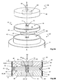
- FIGS. 2A and 2B show, respectively exploded and deformed position, a connection device associated with terminals according to a preferred embodiment of the invention.
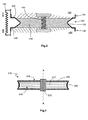
- the figure 3 represents another embodiment of a connector according to the invention.
- the figure 4 illustrates another embodiment of a connection device according to the invention.
- a connector according to the invention is set up easily, by simple positioning and clamping, without insertion force; it corresponds to the flattening of the contact surfaces between terminals and connector so that the separation between two terminals can be reduced in a ratio of 5 to 10 with respect to a conical connection, being for example less than 10 or 15 mm; the interface, however, retains a sufficient size to ensure adequate dielectric strength.
- the various elements composing the connectors according to the invention, illustrated in Figure 2A namely the terminals of the wafers and the connector as such, are modified, to allow a stack by plane contacts, simple to achieve.
- connection device 10 is symmetrical with respect to its median plane, so that it can be used indifferently in one direction or the other ; it is however possible that the connection device 10 has a preferred orientation, especially when the two terminals to be connected are not similar.
- connection device 10 comprises a rod 12 of high electrical conductivity, in particular copper or aluminum, which extends along a longitudinal axis AA between two circular end faces, or connection discs, 14, 14 ' parallel used to ensure the electrical connection.
- the conductive rod 12 is preferably cylindrical of revolution; its diameter is, among others, determined by the transmitted current, and can be increased to compensate for any misalignment faults, or even arrangements arranged inside the rod.
- the rod 12 is integrated in an insulating support 16, whose characteristics and in particular the dielectric strength allow the management of the voltage; moreover, in view of the dielectric stresses, the interface between the rod 12 and the support 16 is controlled and optimized, especially tight, that is to say, free of air.
- the integration between rod 12 and support 16 is for example carried out by overmoulding or force-feeding to ensure a lack of air between the two components.
- the insulating support 16 of the connection device 10 comprises two opposite end faces 18, 18 ', which are in contact with the terminals for their connection; it is electrostatically shielded, that is to say covered with a conductive coating 20 on the non-connecting surfaces to maintain the field lines inside the support 16.
- the connector 10 according to the invention being flat , the size of the support 16 is much greater than that of the rod 12 orthogonal to the axis AA, so that the electric field remains in acceptable values with respect to the characteristics of the material of the support 16; in this respect, it may depend on the operating temperature at which the connection is intended.
- the support 16 is in the form of a washer whose end faces 18, 18 'are circular, advantageously stackable, and the rod 12 is centered thereon; however, it is possible to adopt any suitable form.
- a groove 22 (see Figure 2B ) of adapted form is preferably present on the periphery of the connecting device 10, on which the shielding coating 20 is positioned.
- connection device 10 is used to connect two terminals 30, 30 '; although presenting in the explanatory diagram figures 2 different profiles, according to the preferred embodiment, the terminals 30, 30 'are identical, and symmetrical to each other with respect to the plane of symmetry of the connector 10.
- a terminal 30 used for the connection according to the principle of the invention comprises a conductive insert 32 to be connected via a connection surface 34, and an insulating body 36.
- the insulating body 36 comprises a plane connecting surface 38 which will interface with an end face 18 of the connection device 10 according to the invention.
- the terminal 30 is further electrostatically shielded and the conductive coating 40 delimits the connecting surface 38 so as to ensure continuity with the shield 20 of the connector 10.
- the shielding may be provided with guide protrusions and / or positioning 42 '.
- each connecting surface 38, 38 'of the terminal 30, 30' is superimposable with one of the end faces 18, 18 'of the connector 10.
- the terminals 30, 30' can be circular protruding on electrical equipment 3 '; as schematized in figure 3 (In which the reference signs are increased by 100), the terminals 130, 130 'can also be integrated in a flat surface of said apparatus 103, 103', the shielding 140, 140 'delimiting the connecting surfaces.
- the electrical continuity between the inserts 32, 32 'of the two terminals 30, 30' is ensured, via the rod 12, by the contacts between the connection surfaces 34, 34 'of the terminals and the connection discs 14, 14' of the rod 12: the discs 14, 14 'are inscribed in the connecting surfaces 34, 34', which are flat and orthogonal to the axis AA of the rod 12.
- connection according to the invention is therefore produced by a double planar contact between insulating surfaces 18, 38 and conducting surfaces 14, 34 in order to ensure the dielectric strength and the electric contact.
- the insulating support 16 of the connector 10 has been chosen to be deformable, or compressible, particularly in the direction defined by its axis AA.
- the insulating support 16 is brought into contact with the insulating connection surfaces 38, 38 'of the terminals, then, by orthogonal crushing, the conductive rod 12 comes into contact with the conductive insert 32, 32' of the terminals.
- the distance separating the connecting surface 38 from the connection surface 34 of a terminal 30 along the axis AA is thus greater than the distance separating the connection disc 14 from the end face 18 a connector 10: the distance separating the two end faces 18, 18 'of the support 16 at rest is greater than the desired final spacing of the terminals MT 30, 30'; for example, a compression of the insulator 16 of the order of 0.3 to 0.5 mm on each side is adapted for terminals 30, 30 'separated by 10 to 15 mm.
- the difference in thickness is adapted to the nature of the insulating material 16, but also to the operating temperature of the connectors to compensate for any decompressions due to differential expansion, especially at a very low temperature.
- connection surface 34 of the terminal 30 is recessed, towards the inside of the terminal, so as to form a recess 44 in the connection surface 38.
- the support 16 of the connector 10 is deformed in compression orthogonal to its faces 18, 18 ', to avoid contamination of the connection disc 14 and ensure a "clean" interface, it is preferred that the rod 12 protrudes from the end face 18 of the connection device, by example of 0.5 mm; this embodiment further allows guiding and pre-positioning of the connection device 10 on the terminal 30.
- the rod 12 of the connection device 10 is placed in the recesses 44, 44 'of the terminals 30, 30', and contacts are provided between the conductive surfaces 14, 34 and the insulators 18, 38.
- an assembly clearance between the two terminals 30, 30 'can thus be allowed, allowing an alignment tolerance of the devices 3, 3', and thus facilitating the installation of the elements. .
- the insert 32 of the terminals according to the invention is advantageous for the insert 32 of the terminals according to the invention to be greater in size than its connection surface 34: the insulator of the body 36 of the terminal 30 thus forms an outgrowth 46, that is to say an a kind of neck or neck, around the conductive insert 32, which is "embedded", embedded in the insulating material 36: the residual air in the recess 44 does not ionize, the insert 32 then ensuring a deflection function and thereby minimizing the dielectric stresses caused by the air trapped in the mounting clearance 44.
- the deflector 32 may be in the illustrated form of a cylinder with blunt corners, but other configurations are possible, according to the desired characteristics and control of the triple point represented by the interface at the level of the recess 44; this critical aspect of the dielectric strength of a shielded connection, previously complex because of the multiple layers present at the interface, is therefore, according to the invention, solved by a simple geometric optimization (shape of the deflector 32, relative dimensions of the recess 44 and connecting rod 12, thickness of the insulator 16 between the rod 12 and the electrostatic shield 20, thickness of the insulator 36 between the conductive insert 32 and the shield 40 of the terminal, length of the collar 46 insulation).
- each terminal 30 is connected, as usual, to the power supply system 48 of the equipment that it serves to connect, for example with screwing, soldering, or any other appropriate solution.
- the interfaces are controlled and optimized.
- the first interface between the conductive insert 32 and the insulating body 36 of each terminal 30 is sealed, that is to say air-free, "bonded", with a copper or aluminum over-molding by a thermosetting material of the epoxy type.
- the compression between insulating connection surface 38 and insulating end face 18 makes it possible to evacuate any air present at the second interface; it might be considered to use a sealing grease, but a control, or even a cleaning, of the surface conditions usually makes it possible to get rid of it.
- the insulating material 16 of the connection device 10 is composed of an elastomer whose dielectric qualities are known and optimized, in particular as regards the compactness, in particular of the silicone or the terpolymer of ethylene-propylene-diene or EPDM (for: " Ethylene-Propylene Diene Monomer Rubber "). This material is overmolded on the rod 12, advantageously with a bonding agent, to ensure a cohesive and flawless interface.
- the electrostatic shielding 20 may be made by depositing a metal layer, for example a surface metallization; the formation of the semiconductor element 20 which provides the shielding can also be carried out by overmolding with an elastomer of the same type as the support 16 but loaded with conductive particles, which makes it possible to retain the same compression properties on the all of the connection device 10, between insulating support 16 and shielding 20; deburring is preferably carried out before the shielding 20 is put in place.
- the support 116 is made of a bi-component silicone type insulating foam such as polydimethylsiloxane, which may for example be molded, then cut, with forced insertion of the rod 112 of copper.
- the shield 120 may for example be composed of a coating of the paint type.
- An option represented in figure 4 comprises a support 216 made of two different materials: a dielectric gel 215, for example silicone, polymerized is applied on either side of a rigid insulating core 217 (not deformable), for example epoxy or ceramic; the thickness of the gel 215 which forms the connection surfaces 218 is sufficient to ensure a good seal, that is to say to be compressed in the desired proportions.
- the shape of the insulating core 217 is preferably identical to that of the support 216, which is simply smaller in the direction of the axis AA of the rod 212 of the connection device 210.
- the controlled field shielding 220 may for example be realized by a metallic paint type coating.
- the choice of the insulating material (s) depends on the desired properties, and in particular on the size of the connection device 10, whose diameter is a function of the dielectric properties and the size of the rod 12, itself a function of the value of the current passing through it; in particular, the EPDM connection device 10 corresponding to the figure 2 can have a diameter of 50 to 100 mm, in particular 75 mm, on a height compressed from 10 mm to 15 mm.
- the embodiment of the figure 3 is conventionally of greater diameter (from 100 to 125 mm) because of the nature of the foam, which, usually, is deformed with a higher compression, in particular of the order of 1.5 mm on each face to achieve a separation between the two terminals 130, 130 'from 7 to 12 mm.
- the foam with a density of less than 400 kg / m 3 , comprises closed cells whose size is less than 150 ⁇ m, and preferably less than 50 ⁇ m.
- a semiconductor elastomer can be put in place in the insulation of a connector 10 according to the figure 1 , around the insert 12 so as to increase the protection quality of the triple points, or to adapt to dimensional constraints of the inserts 32 of the terminals 30 and / or thickness of the insulator 16 of the connector 10.
- a first terminal 30 ' is put in place, with its connection surface 38' accessible.
- a connector 10 is positioned on the terminal 30 ', with pre-positioning of the rod 12 in the recess 44', and contact between the end face 18 'of the insulating support 16 and the connecting surface 38'.
- one second terminal 30 is placed opposite the first, with pre-positioning of its recess 44 around the connection disc 14 of the rod 12 and contact of its connecting surface 38 on the second end face 18.
- a parallel compression 50 to the axis AA is then provided until the connection discs 14, 14 'of the rod 12 are in contact with the connection surfaces 34, 34' of the terminals 30, 30 ', and the assembly is maintained in this position.
- Clamping and holding in position can be achieved by the inertia of one apparatus on the other: for example, in the embodiment of a superposition of slabs 3 according to the Figure 1A , the weight of the upper slabs and busbars may be sufficient to provide the connection.
- Other means may be envisaged, for example a screwing system, a version 150 of which is offset to the two apparatuses 103, 103 'is schematized in FIG. figure 3 ; advantageously, the tightening torque is controlled, depending on the hardness of the deformable material, so as to remain in calculated compression margins.
- the flat interface connection according to the invention makes it possible to make the electrical connection between two wafers 3 of the transformer 1 illustrated in FIG. figures 1 .
- the patties as presented in the document EP 1 973 126 , have several outputs 4 so as, for example, to adjust the primary voltages, it is advantageous to further have a spacer corresponding to an insulating connection system: two terminals 4 of the slab 3 are provided with a device 10 according to the invention, and the third is provided with the same device whose rod 12 is made of insulating material, preferably of comparable stiffness.
- the stacking is balanced.
- Such a set of connectors 10 and spacers of identical dimensions can be used for any other assembly.
- connection according to the principle of the invention is carried out by a device 10, 110, 210 advantageously cylindrical and of small thickness, consisting of a conductive insert 12, 112, 212 overmolded with an insulator 16, 116, 217 ( EPDM or foam or bi-material), itself coated with a coating 20, 120, 220 (metallized or semiconductor) on the outer surface to perform the electrostatic shielding.
- the connector is fully shielded, therefore insensitive to the environment; the dielectric seal is made by compression of the insulating support 16, 116, 215 and the electrical contact is made by contact with the conductive rod 12, 112, 212.
- the compression force is achieved for example thanks to a bolted system 150, which can be deported to the apparatus 103, 103 ', such as the wafers of the transformer
- the device 10 according to the invention thus allows a connection easier and faster than the traditional bicones 5, especially without force insertion to ensure seals.
- the simpler interface with a bilayer system unlike the three layers of the prior art, can optimize the dielectric strength and reduce costs; in particular, even the presence of residual air at the deflector 32 can be tolerated by controls on the various elements 12, 32, 44.
- increased tolerances in the dimensions of different components allow a reduction in manufacturing constraints with associated savings.
- the assembly itself is facilitated, thanks to easy management of the misalignment faults between the connection terminals of the equipment, a clearance on each of the three axes being acceptable, which generates a saving of time and a reduced cost.
- the invention has been described with reference to the connection of two wafers 3, 3 'of a transformer coil 2, it is not limited thereto: other devices may be concerned by the invention.
- the terminals of the modular assemblies can be modified for a flat interface connection as described; the device and method according to the invention are also particularly suitable for connecting two functions of an electrical equipment, for example the connection between a disconnector, a vacuum interrupter, a circuit breaker, a busbar, ....
Landscapes
- Connector Housings Or Holding Contact Members (AREA)
- Multi-Conductor Connections (AREA)
- Coupling Device And Connection With Printed Circuit (AREA)
- Liquid Crystal (AREA)
- Manufacturing Of Electrical Connectors (AREA)
Abstract
Description
- L'invention concerne la simplification de la connexion entre bornes adjacentes d'appareillages électriques, en particulier pour la haute ou moyenne tension. Les bornes auxquelles se rapporte l'invention sont de géométrie adaptée, avec un corps isolant ayant une surface de raccordement plane munie d'un évidement dans lequel débouche un insert conducteur.
- Sous un aspect, l'invention concerne un procédé de raccordement de deux bornes planes situées en regard l'une de l'autre par interposition d'un dispositif de connexion plat généralement isolant dans lequel une tige conductrice est surmoulée ; un contact entre la tige conductrice et les inserts conducteurs des bornes est obtenu par une étape d'écrasement de l'isolant du dispositif de connexion par les bornes.
- Sous un autre aspect, l'invention se rapporte à un dispositif adapté à ce type de connexion, comprenant un support isolant plat déformable duquel dépasse, en situation d'écrasement par compression, une tige conductrice ; le dispositif selon l'invention peut être utilisé conjointement avec des moyens de serrage pour pérenniser la connexion.
- Les appareils électriques comprennent de nombreux modules qui doivent être reliés électriquement l'un à l'autre. Certains appareils concernent en outre des tensions élevées, notamment la moyenne tension MT, c'est-à-dire de l'ordre de 5 à 52 kV (parfois aussi appelée haute tension HT), de sorte qu'il est avantageux d'isoler les liaisons, voire même de les blinder
- Ainsi par exemple, dans un transformateur 1 moyenne tension/basse tension MT/BT, il est possible de réaliser l'un des enroulements, par exemple la bobine moyenne tension 2, par une superposition de galettes de puissance 3, 3', dont le nombre permet d'ajuster la puissance. Un mode de réalisation préféré, illustré schématiquement en
figures 1A et 1B , est par exemple présenté dans le documentEP 1 973 126 , dans lequel des galettes 3 à plusieurs sorties munies de bornes de raccordement 4 permettent en outre l'ajustement de la tension d'entrée. - La connexion entre deux appareillages électriques adjacents 3, superposés ou placés côte à côte, peut être réalisée par l'intermédiaire d'interfaces de type bicônes 5, tels que décrits dans le document
FR 2 766 019 figure 1C , insérés dans des bornes 4. L'insertion de ce type de dispositif dans les bornes 4 doit cependant être suffisante afin d'assurer le contact nécessaire à la connexion électrique et à la tenue diélectrique, de sorte que le positionnement des bornes 4 en regard doit être précis. En particulier, dans le cadre illustré enfigures 1 , la gestion des défauts de désaxage entre les points de connexion 4 des galettes 3 peut devenir complexe. - Par ailleurs, les dispositifs de raccordement 5 de type bicônes sont encombrants en hauteur, afin de garantir une tenue diélectrique suffisante, notamment pour les applications moyenne tension : tel que rappelé dans le document
WO 07/065912 - Parmi autres avantages, l'invention vise à pallier des inconvénients des dispositifs de connexion existants et notamment à restreindre leur encombrement tout en simplifiant la mise en oeuvre des raccordements électriques.
- La liaison électrique est réalisée directement, sans pièce intermédiaire, entre des éléments de connexion à champ dirigé dont les surfaces actives sont superposables. Au vu de l'application préférée pour des tensions élevées, et de la nécessaire maîtrise des lignes de fuite de tension, l'interface de contact est réalisée de façon à éviter la présence d'espaces susceptibles de générer des arcs électriques ; parallèlement, la surface est suffisamment étendue pour pallier les problèmes locaux de surtension.
- Sous un aspect, l'invention se rapporte à une connectique comprenant deux bornes en regard raccordées par un dispositif de connexion ; avantageusement, les deux bornes sont identiques, et le dispositif de connexion est symétrique par rapport à son plan médian ; de préférence, les bornes ont des surfaces de raccordement circulaires, et le dispositif de connexion est symétrique de révolution.
- Chaque borne comprend un corps isolant avec une surface plane de raccordement, un revêtement de blindage électrostatique du corps isolant délimitant la surface de raccordement. Un insert conducteur est intégré au corps isolant, à l'exception d'une surface de connexion, avantageusement circulaire, qui débouche dans un évidement formé dans la surface de raccordement isolante ; de préférence, l'insert conducteur est de taille supérieure à sa surface de connexion et le corps isolant forme un enrobage de l'insert, avec une protubérance au niveau de son extrémité, de façon à avoir en outre une fonction de déflecteur. La surface de connexion de l'insert est parallèle à la surface de raccordement de la borne.
- Entre les deux bornes en regard se met en place un dispositif de connexion qui comprend une tige conductrice pouvant pénétrer dans les évidements des bornes, et pouvant entrer en contact avec les surfaces de connexion par ses deux extrémités, formées par des disques de connexion parallèles. La tige conductrice est intégrée dans un support qui comprend au moins un matériau isolant déformable qui peut être écrasé ; le support est plat, et comprend un pourtour et deux faces d'extrémité sensiblement planes, ou légèrement coniques, qui peuvent être superposées de façon étanche aux surfaces de raccordement des bornes lorsque le support est pressé entre ses faces d'extrémité ; de préférence, la tige fait saillie des faces d'extrémité du support. Le dispositif de connexion est blindé pour contenir le champ électrique, avec un revêtement conducteur sur son pourtour, qui peut avantageusement comprendre une gorge radiale permettant entre autres un guidage de la déformation.
- L'intégration de la tige dans le support du dispositif de connexion peut être réalisée notamment par un surmoulage d'un élastomère, par exemple de l'EPDM ou du silicone, sur la tige ; le blindage électrostatique est avantageusement composé d'un surmoulage du même matériau dans lequel des charges conductrices ont été mises en place. Une autre option pour le support est une mousse compressible, revêtue par une peinture conductrice. Il est possible également que le support soit composé de plusieurs matériaux, et notamment d'un coeur rigide de type époxy ou céramique recouvert au niveau des faces d'extrémités d'un gel diélectrique polymérisé. Un élastomère semi-conducteur peut quant à lui être mis en place autour des inserts.
- La connexion est réalisée entre les trois composants de la connectique par écrasement en compression du support du dispositif de connexion de sorte que les interfaces entre ses faces d'extrémité et les surfaces de raccordement des bornes, et entre ses disques de connexion et les surfaces de connexion des bornes, soient étanches. Les bornes peuvent être associées à des moyens de serrage pour maintenir cet état.
- L'invention concerne sous un autre aspect un appareillage électrique comprenant plusieurs parties, notamment un dispositif de type cellule moyenne tension comprenant disjoncteur, sectionneur et/ou interrupteur, qui sont reliées entre elles par une ou plusieurs connectiques définies plus haut. Le dispositif de connexion précédent est également un objet de l'invention.
- Selon un mode de réalisation préféré, le dispositif de connexion selon l'invention est utilisé pour raccorder des galettes de puissance pour former une bobine de transformateur.
- Avantageusement, le dispositif selon l'invention fait partie d'un ensemble de connecteurs identiques, comprenant en outre également des entretoises de liaison, lesdites entretoises étant de géométrie et conception similaires aux dispositifs de connexion, à l'exception de la tige qui est formée dans un matériau isolant, de préférence non déformable : suivant le raccordement souhaité, soit une conduction est assurée, soit les deux bornes sont isolées l'une de l'autre.
- Sous un autre aspect, l'invention se rapporte à un procédé de raccordement électrique de deux bornes comprenant chacune une surface de connexion plane formant un évidement dans la surface plane d'un corps isolant blindé électrostatiquement, dans lequel un dispositif de connexion comprenant une tige conductrice intégrée à un support isolant plat susceptible d'être écrasé dans le sens de la tige et blindé électrostatiquement est mis en place sur une première borne, la face de connexion de la tige étant localisée face à l'évidement et le support isolant étant en contact avec la première borne. La deuxième borne est mise en place sur le dispositif de connexion, avec son évidement en regard de l'autre face de connexion de la tige et avec un contact entre sa surface de raccordement et le support isolant. L'ensemble est ensuite comprimé ou écrasé, avec déplacement des bornes l'une vers l'autre de sorte que les faces de connexion de la tige se placent en contact avec les surfaces de connexion des bornes ; la déformation peut être maintenue tant que le raccordement électrique est souhaité.
- D'autres avantages et caractéristiques ressortiront plus clairement de la description qui suit de modes particuliers de réalisation de l'invention, donnés à titre illustratif et nullement limitatifs, représentés dans les figures annexées.
- Les
figures 1A à 1C , déjà décrites, illustrent un système de connexion existant utilisé pour le raccordement de galettes de transformateur modulaire. - Les
figures 2A et 2B montrent, respectivement en éclaté et en position déformée, un dispositif de connexion associé à des bornes selon un mode de réalisation préféré de l'invention. - La
figure 3 représente un autre mode de réalisation d'une connectique selon l'invention. - La
figure 4 illustre un autre mode de réalisation d'un dispositif de connexion selon l'invention. - Bien que pouvant être utilisée pour relier entre eux différentes parties juxtaposées d'un appareillage électrique quelconque et notamment haute tension, l'invention sera décrite pour une application préférée à une partie active 2 de transformateur 1 à galettes 3 tel que présenté plus haut en relation avec la
figure 1 et présenté par exemple dans la demande de brevetEP 1 973 126 . En particulier, les dimensions données ci-après sont adaptées pour une connexion à 20 A et 20-24 kV. Il est entendu cependant que les exemples ne sont qu'illustratifs et que les dimensions et/ou matériaux, voire formes, peuvent être adaptées et optimisées en fonction du courant transporté et de la tension appliquée. - Une connectique selon l'invention est mise en place de façon aisée, par simple positionnement et serrage, sans insertion à force ; elle correspond à l'aplatissement des surfaces de contact entre bornes et connecteur de sorte que la séparation entre deux bornes peut être réduite dans un rapport de 5 à 10 par rapport à une connexion conique, en étant par exemple inférieure à 10 ou 15 mm ; l'interface conserve cependant une dimension suffisante pour garantir la tenue diélectrique adéquate. Les différents éléments composant la connectique selon l'invention, illustrés en
figure 2A , à savoir les bornes des galettes et le connecteur en tant que tel, sont donc modifiés, pour permettre un empilement par contacts plans, simple à réaliser. - Avantageusement, le dispositif de connexion 10 selon l'invention est symétrique par rapport à son plan médian, de sorte qu'il peut être utilisé indifféremment dans un sens ou l'autre ; il est cependant possible que le dispositif de connexion 10 ait une orientation préférentielle, notamment lorsque les deux bornes à connecter ne sont pas similaires.
- Le dispositif de connexion 10 comprend une tige 12 de forte conductivité électrique, notamment en cuivre ou en aluminium, qui s'étend le long d'un axe longitudinal AA entre deux faces d'extrémité circulaires, ou disques de connexion, 14, 14' parallèles qui servent à assurer le raccordement électrique. Par souci de simplifications de fabrication et/ou calcul, la tige conductrice 12 est de préférence cylindrique de révolution ; son diamètre est, entre autres, déterminé par le courant transmis, et peut être augmenté pour compenser d'éventuels défauts de désaxage, voire des aménagements disposés à l'intérieur de la tige.
- La tige 12 est intégrée à un support isolant 16, dont les caractéristiques et notamment la rigidité diélectrique permettent la gestion de la tension ; de plus, au vu des contraintes diélectriques, l'interface entre la tige 12 et le support 16 est contrôlée et optimisée, notamment étanche, c'est-à-dire exempte d'air. L'intégration entre tige 12 et support 16 est par exemple réalisée par un surmoulage ou un emmanchage à force afin d'assurer une absence d'air entre les deux composants.
- Le support isolant 16 du dispositif de connexion 10 selon l'invention comprend deux faces d'extrémité opposées 18, 18', qui sont en contact avec les bornes pour leur raccordement ; il est blindé électrostatiquement, c'est-à-dire recouvert d'un revêtement conducteur 20 sur les surfaces ne servant pas au raccordement pour maintenir les lignes de champ à l'intérieur du support 16. Le connecteur 10 selon l'invention étant plat, la taille du support 16 est très supérieure à celle de la tige 12 orthogonalement à l'axe AA, afin que le champ électrique reste dans des valeurs acceptables par rapport aux caractéristiques du matériau du support 16 ; à cet égard, elle peut dépendre de la température de fonctionnement à laquelle la connectique est destinée. De préférence, afin d'éviter tout effet de pointe, le support 16 se présente sous forme d'une rondelle dont les faces d'extrémité 18, 18' sont circulaires, avantageusement superposables, et la tige 12 y est centrée ; il est cependant possible d'adopter toute forme adaptée. Afin de diminuer le diamètre du support 16 tout en assurant une bonne tenue diélectrique, une gorge 22 (voir
figure 2B ) de forme adaptée est de préférence présente sur le pourtour du dispositif de raccordement 10, sur laquelle est positionné le revêtement 20 de blindage. - Le dispositif de connexion 10 selon l'invention est utilisé pour raccorder deux bornes 30, 30' ; bien que présentant dans le schéma explicatif des
figures 2 des profils différents, selon le mode de réalisation préféré, les bornes 30, 30' sont identiques, et symétriques l'une à l'autre par rapport au plan de symétrie du connecteur 10. - Une borne 30 utilisée pour la connectique selon le principe de l'invention comprend un insert conducteur 32 à relier par l'intermédiaire d'une surface de connexion 34, et un corps isolant 36. Selon l'invention, le corps isolant 36 comprend une surface de raccordement 38 plane qui assurera l'interface avec une face d'extrémité 18 du dispositif de connexion 10 selon l'invention. La borne 30 est en outre blindée électrostatiquement et le revêtement conducteur 40 délimite la surface de raccordement 38 de sorte à assurer une continuité avec le blindage 20 du connecteur 10. Afin d'assurer un positionnement correct du connecteur plan 10 sur une borne 30, le blindage peut être muni de protubérances de guidage et/ou positionnement 42'.
- Il apparaît ainsi que chaque surface de raccordement 38, 38' de la borne 30, 30' est superposable avec une des faces d'extrémité 18, 18' du connecteur 10. En particulier, les bornes 30, 30' peuvent être en saillies circulaires sur les appareillages électriques 3' ; tel que schématisé en
figure 3 (dans laquelle les signes de références sont augmentés de 100), les bornes 130, 130' peuvent également être intégrées dans une surface plane desdits appareillages 103, 103', le blindage 140, 140' délimitant les surfaces de raccordement. - La continuité électrique entre les inserts 32, 32' des deux bornes 30, 30' est assurée, via la tige 12, par les contacts entre les surfaces de connexion 34, 34' des bornes et les disques de connexion 14, 14' de la tige 12 : les disques 14, 14' sont inscrits dans les surfaces de connexion 34, 34', qui sont planes et orthogonales à l'axe AA de la tige 12.
- La connexion selon l'invention est donc réalisée par un double contact plan, entre surfaces isolantes 18, 38 et surfaces conductrices 14, 34 afin d'assurer la tenue diélectrique et le contact électrique. Compte tenu de la présence d'un double contact plan, hyperstatique, pour garantir la qualité des interfaces et éviter notamment toute présence d'air à ce niveau, le support isolant 16 du connecteur 10 a été choisi déformable, ou compressible, notamment dans la direction définie par son axe AA. En particulier, le support isolant 16 est mis en contact avec les surfaces de raccordement isolantes 38, 38' des bornes, puis, par écrasement orthogonal, la tige conductrice 12 vient en contact sur l'insert conducteur 32, 32' des bornes.
- Selon l'invention, la distance séparant la surface de raccordement 38 de la surface de connexion 34 d'une borne 30 le long de l'axe AA est donc supérieure à la distance séparant le disque de connexion 14 de la face d'extrémité 18 d'un connecteur 10 : la distance séparant les deux faces d'extrémité 18, 18' du support 16 au repos est supérieure à l'écartement final souhaité des bornes MT 30, 30' ; par exemple, une compression de l'isolant 16 de l'ordre de 0,3 à 0,5 mm de chaque côté est adaptée pour des bornes 30, 30' séparées de 10 à 15 mm. La différence d'épaisseur est adaptée à la nature du matériau isolant 16, mais également à la température de fonctionnement de la connectique afin de compenser d'éventuelles décompressions dues aux dilatations différentielles, notamment à très faible température.
- En particulier, la surface de connexion 34 de la borne 30 est en retrait, vers l'intérieur de la borne, de façon à former un évidement 44 dans la surface de raccordement 38. Par ailleurs, comme le support 16 du connecteur 10 se déforme en compression orthogonale à ses faces 18, 18', pour éviter toute contamination du disque de connexion 14 et garantir une interface « propre », il est préféré que la tige 12 fasse saillie de la face d'extrémité 18 du dispositif de connexion, par exemple de 0,5 mm ; ce mode de réalisation permet en outre un guidage et un pré-positionnement du dispositif de connexion 10 sur la borne 30.
- Une fois la déformation achevée, selon le mode de réalisation illustré en
figure 2B , on a donc la tige 12 du dispositif de connexion 10 mise en place dans les évidements 44, 44' des bornes 30, 30', et des contacts assurés entre les surfaces conductrices 14, 34 et isolantes 18, 38. La taille de l'évidement 44' peut être ajustée au diamètre de la tige 12 ; cependant, grâce à la solution selon l'invention, il est possible et préféré que le diamètre de la tige 12 soit inférieur au diamètre de l'évidement 44 : en effet, bien que de l'air puisse alors être piégé dans l'espace résiduel, les contraintes diélectriques sont contrôlées et faibles. En particulier, contrairement au système de bicône 5, un jeu d'assemblage entre les deux bornes 30, 30' peut ainsi être permis, permettant une tolérance à l'alignement des appareillages 3, 3', et facilitant ainsi l'installation des éléments. - Il est avantageux que l'insert 32 des bornes selon l'invention 30 soit de taille supérieure à sa surface de connexion 34 : l'isolant du corps 36 de la borne 30 forme ainsi une excroissance 46, c'est-à-dire une sorte de goulot ou de col, autour de l'insert conducteur 32, qui est « noyé », enrobé, dans le matériau isolant 36 : l'air résiduel dans l'évidement 44 ne s'ionise pas, l'insert 32 assurant alors une fonction de déflexion et minimisant par là les contraintes diélectriques causées par l'air piégé dans le jeu de montage 44. Le déflecteur 32 peut se présenter sous la forme illustrée d'un cylindre à coins émoussés, mais d'autres configurations sont possibles, suivant les caractéristiques souhaitées et la maîtrise du point triple représenté par l'interface au niveau de l'évidement 44 ; cet aspect critique de la tenue diélectrique d'une connectique blindée, auparavant complexe en raison des multiples couches présentes à l'interface, est donc, selon l'invention, résolu par une optimisation géométrique simple (forme du déflecteur 32, dimensions relatives de l'évidement 44 et de la tige de connexion 12, épaisseur de l'isolant 16 entre la tige 12 et le blindage électrostatique 20, épaisseur de l'isolant 36 entre l'insert conducteur 32 et le blindage 40 de la borne, longueur du col 46 isolant).
- L'insert conducteur 32 de chaque borne 30 est relié, tel qu'usuel, vers le système d'alimentation 48 des appareillages qu'il sert à connecter, par exemple avec un vissage, un brasage, ou toute autre solution appropriée.
- Pour éviter les amorçages lors du raccordement électrique et limiter la présence de points triples au seul jeu contrôlé entre tige 12 et corps isolant 36 au niveau de l'évidement 44, les interfaces sont maîtrisées et optimisées. En particulier, la première interface entre insert conducteur 32 et corps isolant 36 de chaque borne 30 est étanche, c'est-à-dire exempt d'air, « adhérisé », avec de préférence un surmoulage de cuivre ou d'aluminium par un matériau thermodurcissable de type époxy.
- La compression entre surface de raccordement 38 isolante et face d'extrémité 18 isolante permet d'évacuer l'air éventuellement présent à la deuxième interface ; il pourrait être envisagé d'utiliser une graisse d'étanchéité, mais un contrôle, voire un nettoyage, des états de surface permet habituellement de s'en affranchir. Il peut être avantageux d'avoir un léger gradient d'épaisseur, décroissant depuis le centre du connecteur 10 vers son pourtour, c'est-à-dire une forme légèrement conique, afin d'aider cette évacuation (non illustré) ; lorsqu'un jeu dans l'évidement 44 est prévu, il peut être envisagé d'avoir un gradient d'épaisseur croissant depuis le centre du connecteur 10 vers son pourtour, c'est-à-dire une forme concave, permettant d'équilibrer les pressions d'écrasement et évacuant l'air vers l'évidement 44 où les contraintes diélectriques sont maîtrisées.
- La troisième interface entre tige conductrice 12 et support isolant 16 du connecteur 10 est réalisée également de façon étroite. Selon un premier mode de réalisation illustré en
figure 2A , le matériau isolant 16 du dispositif de connexion 10 est composé d'un élastomère dont les qualités diélectriques sont connues et optimisées, notamment en ce qui concerne la compacité, en particulier du silicone ou du terpolymère d'éthylène-propylène-diène ou EPDM (pour : « Ethylene-Propylene Diene Monomer rubber »). Ce matériau est surmoulé sur la tige 12, avec avantageusement présence d'un agent d'adhérisation, pour assurer une interface cohésive et sans défaut. Le blindage électrostatique 20 peut être réalisé par dépôt d'une couche de métal, par exemple une métallisation en surface ; la formation de l'élément semi-conducteur 20 qui assure le blindage peut également être réalisée par un surmoulage avec un élastomère de même type que le support 16 mais chargé de particules conductrices, ce qui permet de conserver les mêmes propriétés de compression sur l'ensemble du dispositif de connexion 10, entre support isolant 16 et blindage 20 ; un ébavurage est de préférence effectué avant la mise en place du blindage 20. - Selon une autre option illustré en
figure 3 , le support 116 est réalisé dans une mousse isolante de type silicone bi-composant comme le polydiméthylsiloxane, qui peut par exemple être moulée, puis découpée, avec insertion à force de la tige 112 de cuivre. Tel qu'illustré enfigure 3 , le blindage 120 peut par exemple être alors composé d'un revêtement de type peinture. - Une option représentée en
figure 4 comprend un support 216 réalisé en deux matériaux distincts : un gel diélectrique 215, par exemple du silicone, polymérisé est appliqué de part et d'autre d'un coeur isolant 217 rigide (non déformable), par exemple en époxy ou en céramique ; l'épaisseur du gel 215 qui forme les surfaces de connexion 218 est suffisante pour assurer une bonne étanchéité, c'est-à-dire pour être comprimée dans les proportions voulues. La forme du coeur isolant 217 est de préférence identique à celle du support 216, simplement plus petite dans le sens de l'axe AA de la tige 212 du dispositif de connexion 210. Le blindage à champ dirigé 220 peut par exemple être réalisé par un revêtement de type peinture métallique. - Le choix du (des) matériau(x) isolant(s) dépend des propriétés souhaitées, et notamment de la taille du dispositif de connexion 10, dont le diamètre est fonction des propriétés diélectriques et de la taille de la tige 12, elle-même fonction de la valeur du courant y transitant ; en particulier, le dispositif de connexion 10 en EPDM correspondant à la
figure 2 peut faire un diamètre de 50 à 100 mm, notamment 75 mm environ, sur une hauteur comprimée de 10 mm à 15 mm. Le mode de réalisation de lafigure 3 est classiquement de diamètre supérieur (de 100 à 125 mm) en raison de la nature de la mousse, qui, usuellement, est déformée avec une compression supérieure, notamment de l'ordre de 1,5 mm sur chaque face pour arriver à une séparation entre les deux bornes 130, 130' de 7 à 12 mm. La mousse, de densité inférieure à 400 kg/m3, comprend des cellules fermées dont la taille est inférieure à 150 µm, et de préférence inférieure à 50 µm. - Selon une option non illustrée, un élastomère semi-conducteur peut être mis en place dans l'isolant d'un connecteur 10 selon la
figure 1 , autour de l'insert 12 de façon à augmenter la qualité de protection des points triples, ou pour s'adapter à des contraintes dimensionnelles des inserts 32 des bornes 30 et/ou d'épaisseur de l'isolant 16 du connecteur 10. - Pour réaliser une connexion selon l'invention, une première borne 30' est mise en place, avec sa surface de raccordement 38' accessible. Un connecteur 10 est positionné sur la borne 30', avec pré-positionnement de la tige 12 dans l'évidement 44', et contact entre la face d'extrémité 18' du support isolant 16 et la surface de raccordement 38'. Puis, une deuxième borne 30 est placée en regard de la première, avec pré-positionnement de son évidement 44 autour du disque de connexion 14 de la tige 12 et contact de sa surface de raccordement 38 sur la deuxième face d'extrémité 18. Une compression 50 parallèle à l'axe AA est alors assurée jusqu'à ce que les disques de connexion 14, 14' de la tige 12 soient en contact avec les surfaces de connexion 34, 34' des bornes 30, 30', et l'assemblage est maintenu dans cette position. Le serrage et le maintien en position peuvent être réalisés par l'inertie d'un appareillage sur l'autre : par exemple, dans le mode de réalisation d'une superposition de galettes 3 selon la
figure 1A , le poids des galettes supérieures et des jeux de barres peut être suffisant pour assurer la connexion. D'autres moyens peuvent être envisagés, par exemple un système de vissage, dont une version 150 déporté vers les deux appareillages 103, 103' est schématisée enfigure 3 ; avantageusement, le couple de serrage est contrôlé, en fonction de la dureté du matériau déformable, de façon à rester dans des marges de compression calculées. - La connectique à interface plane selon l'invention permet de réaliser la connexion électrique entre deux galettes 3 du transformateur 1 illustré en
figures 1 . Si les galettes, tel que présenté dans le documentEP 1 973 126 , présentent plusieurs sorties 4 de façon à, par exemple, pouvoir ajuster les tensions primaires, il est avantageux de disposer en outre d'une entretoise correspondant à un système de connexion isolant : deux bornes 4 de la galette 3 sont munies d'un dispositif 10 selon l'invention, et la troisième est munie du même dispositif dont la tige 12 est réalisée en matériau isolant, avantageusement de rigidité comparable. Ainsi, l'empilement est équilibré. Un tel ensemble de connecteurs 10 et entretoises de dimensions identiques peut être utilisé pour tout autre assemblage. - Ainsi, la connexion selon le principe de l'invention est réalisée par un dispositif 10, 110, 210 avantageusement cylindrique et de faible épaisseur, constitué d'un insert conducteur 12, 112, 212 surmoulé d'un isolant 16, 116, 217 (en EPDM ou en mousse ou bi-matière), lui-même recouvert d'un revêtement 20, 120, 220 (métallisé ou semi-conducteur) sur la surface extérieure pour réaliser le blindage électrostatique. La connectique est entièrement blindée, donc insensible à l'environnement ; l'étanchéité diélectrique est réalisée par compression du support isolant 16, 116, 215 puis le contact électrique est réalisé par le contact de la tige conductrice 12, 112, 212. L'effort de compression est réalisé par exemple grâce à un système boulonné 150, qui peut être déporté sur les appareillages 103, 103', comme les galettes du transformateur
- Le dispositif 10 selon l'invention permet donc un raccordement plus facile et rapide que les bicônes 5 traditionnels, notamment sans insertion à force pour assurer les étanchéités. De plus, l'interface plus simple, avec un système bicouche contrairement aux trois couches de l'art antérieur, permet d'optimiser la tenue diélectrique et de réduire les coûts ; en particulier, même la présence d'air résiduel au niveau du déflecteur 32 peut être tolérée par des contrôles sur les différents éléments 12, 32, 44. Outre la hauteur réduite de raccordement et donc un encombrement restreint, des tolérances accrues dans les dimensions des différents composants permettent une diminution des contraintes de fabrication avec économies afférentes. L'assemblage lui-même est facilité, grâce à une gestion aisée des défauts de désaxages entre les bornes de raccordement des appareillages, un jeu selon chacun des trois axes étant acceptable, ce qui génère un gain de temps et un coût réduit.
- Bien que l'invention ait été décrite en référence à la connexion de deux galettes 3, 3' d'une bobine 2 de transformateur, elle ne s'y limite pas : d'autres appareillages peuvent être concernés par l'invention. Notamment, les bornes des assemblages modulaires peuvent être modifiées pour un raccordement à interface plane tel que décrit ; le dispositif et le procédé selon l'invention sont également particulièrement adaptés pour le raccordement de deux fonctions d'un appareillage électrique, par exemple la liaison entre un sectionneur, un interrupteur à vide, un disjoncteur, un jeu de barres,....
Claims (16)
- Dispositif de connexion (10) pour le raccordement électrique de deux bornes blindées en regard (30, 30'), chaque borne (30) comprenant un corps isolant (36) avec une surface plane de raccordement (38), un revêtement de blindage électrostatique (40) du corps isolant autour de la surface de raccordement (38), et un insert conducteur (32) intégré au corps isolant (36) qui en débouche par une surface de connexion (34), ladite surface (34) étant parallèle à la surface de raccordement (38) et décalée vers l'intérieur du corps de la borne (30) de façon à former un évidement (44) dans la surface plane de raccordement (38), ledit dispositif de connexion (10) comprenant :- un support (16) déformable en matériau isolant comprenant un pourtour et deux faces d'extrémité (18, 18') sensiblement planes, qui peuvent être superposées aux surfaces de raccordement (38, 38') des bornes (30, 30') lorsque le support (16) est déformé par compression entre ses deux faces d'extrémité (18, 18') ;- un revêtement conducteur de blindage électrostatique (20) sur le pourtour du support (16) ;- une tige conductrice (12) cylindrique intégrée dans le support (16) et débouchant sur les faces d'extrémité (18, 18') du support au niveau de deux disques de connexion parallèles (14, 14') qui peuvent être inscrits dans les surfaces de connexion (34, 34') des bornes (30, 30').
- Dispositif de connexion selon la revendication 1 dans lequel la tige conductrice (12) fait saillie par rapport à au moins une face d'extrémité (18) du support isolant (16).
- Dispositif de connexion selon l'une des revendications 1 ou 2 symétrique par rapport à un plan médian des disques de connexion (14, 14') de la tige (12) et/ou dans lequel le support (16) comprend deux faces d'extrémité (18, 18') dont la périphérie est circulaire.
- Dispositif de connexion selon l'une des revendications 1 à 3 dans lequel le support isolant (16) comprend une gorge radiale (22) sur son pourtour, entre les deux faces d'extrémité (18, 18').
- Dispositif de connexion selon l'une des revendications 1 à 4 dans lequel le support (16) est en élastomère isolant surmoulé sur la tige (12).
- Dispositif de connexion selon la revendication 5 dans lequel le revêtement conducteur de blindage électrostatique (20) est un surmoulage du même élastomère que le support isolant (16), lequel élastomère comprenant en outre des charges conductrices.
- Dispositif de connexion selon l'une des revendications 1 à 4 dans lequel le support (116) est dans une mousse isolante compressible et le revêtement conducteur de blindage électrostatique (120) est une peinture appliquée sur la mousse.
- Dispositif selon l'une des revendications 1 à 4 dans lequel le support (216) comprend un coeur (217) en matériau isolant avec deux faces d'extrémité et un gel diélectrique (215) polymérisé appliqué sur les deux faces d'extrémité du coeur isolant, et le revêtement conducteur de blindage électrostatique (220) est une peinture appliquée sur le pourtour du support (216).
- Ensemble comprenant au moins un dispositif de connexion selon l'une des revendications 1 à 8 et au moins une entretoise de liaison, dans lequel les dispositifs de connexion (10) sont identiques entre eux, les entretoises de liaison sont identiques entre elles, et les entretoises de liaison ont les mêmes caractéristiques que les dispositifs de connexion (10), la tige des entretoises étant en matériau isolant.
- Connectique comprenant :- deux bornes (30, 30') à raccorder qui comprennent chacune un corps isolant (36, 36') avec une surface plane de raccordement (38, 38'), un revêtement de blindage électrostatique (40, 40') du corps isolant (36, 36') autour de la surface de raccordement (38, 38'), et un insert conducteur (32, 32') intégré au corps isolant (36, 36') qui en débouche par une surface de connexion (34, 34'), ladite surface (34) étant parallèle à la surface de raccordement (38, 38') et décalée vers l'intérieur du corps de la borne (30, 30') de façon à former un évidement (44, 44') dans la surface plane de raccordement (38, 38') ; et- un dispositif de connexion (10) selon l'une des revendications 1 à 8 dont les disques de connexion (14, 14') peuvent être inscrits dans les surfaces de connexion (34, 34') des bornes en regard (30, 30') et dont le support (16) peut être mis en place entre les deux surfaces de raccordement (38, 38') des bornes en regard (30, 30') puis déformé normalement auxdites surfaces de raccordement (38, 38') pour former une interface étanche et pour que la tige (12) soit en contact avec les surfaces de connexion (34, 34') des bornes en regard (30, 30').
- Connectique selon la revendication 10 dans lequel l'insert conducteur (32) d'au moins une borne (30) est de taille supérieure à sa surface de connexion (34), le corps isolant (36) formant une excroissance (46) autour de l'insert (32).
- Connectique selon l'une des revendications 10 ou 11 dans lequel les deux bornes (30, 30') sont de caractéristiques identiques.
- Connectique selon l'une des revendications 10 à 12 comprenant en outre des moyens de serrage (150) des deux bornes (130, 130') l'une vers l'autre.
- Appareillage électrique comprenant au moins deux parties (3, 3') reliées entre elles par au moins une connectique (30, 10, 30') selon l'une des revendications 10 à 13.
- Procédé de raccordement électrique de deux bornes (30, 30') comprenant chacune une surface de connexion plane (34, 34') formant un évidement (44, 44') dans la surface plane (38, 38') d'un corps isolant blindé électrostatiquement (36, 36') comprenant :- la mise en place sur une première borne (30') d'un dispositif de connexion (10) selon l'une des revendications 1 à 8, de sorte que le premier disque de connexion (14') de sa tige (12) soit localisé face à la première surface de connexion plane (34'), la première face d'extrémité (18') de son support (16) étant en contact avec la surface de raccordement (38') de la première borne (30') ;- le positionnement de la deuxième borne (30) sur le dispositif de connexion (10) de sorte que sa surface de connexion plane (34) soit localisée face au deuxième disque de connexion (14) de la tige (12) du dispositif de connexion (10), la surface de raccordement (38) de la deuxième borne (30) étant en contact avec la deuxième face d'extrémité (18) du support (16) ;- le déplacement des bornes (30, 30') l'une vers l'autre de sorte que le support (16) du dispositif de connexion (10) soit déformé jusqu'à ce que les disques de connexion (14, 14') de sa tige (12) soient en contact avec les surfaces de connexion (34, 34') des bornes (30, 30').
- Procédé selon la revendication 15 comprenant en outre une étape de maintien en position serrée des deux bornes (30, 30') pour assurer la connexion électrique.
Applications Claiming Priority (1)
| Application Number | Priority Date | Filing Date | Title |
|---|---|---|---|
| FR0708127A FR2923954B1 (fr) | 2007-11-20 | 2007-11-20 | Connexion blindee de deux bornes par contact entre interfaces planes. |
Publications (2)
| Publication Number | Publication Date |
|---|---|
| EP2063494A1 true EP2063494A1 (fr) | 2009-05-27 |
| EP2063494B1 EP2063494B1 (fr) | 2010-11-24 |
Family
ID=39540784
Family Applications (1)
| Application Number | Title | Priority Date | Filing Date |
|---|---|---|---|
| EP08354076A Not-in-force EP2063494B1 (fr) | 2007-11-20 | 2008-10-21 | Connexion blindée de deux bornes par contact entre interfaces planes |
Country Status (5)
| Country | Link |
|---|---|
| EP (1) | EP2063494B1 (fr) |
| CN (1) | CN101442163B (fr) |
| AT (1) | ATE489744T1 (fr) |
| DE (1) | DE602008003648D1 (fr) |
| FR (1) | FR2923954B1 (fr) |
Families Citing this family (2)
| Publication number | Priority date | Publication date | Assignee | Title |
|---|---|---|---|---|
| KR102797421B1 (ko) * | 2019-11-27 | 2025-04-21 | 쑤저우 지와이젯 일렉트로닉 테크놀러지 컴퍼니 리미티드 | 압접형 전기 커넥터 |
| CN119994568A (zh) * | 2025-01-07 | 2025-05-13 | 中航光电科技股份有限公司 | 信号端子模块及连接器 |
Citations (7)
| Publication number | Priority date | Publication date | Assignee | Title |
|---|---|---|---|---|
| EP0674375A1 (fr) * | 1994-03-26 | 1995-09-27 | ABBPATENT GmbH | Dispositif amovible d'accouplement de deux conducteurs s'alignant entre eux |
| US5726390A (en) * | 1993-01-21 | 1998-03-10 | Siemens Aktiengesellschaft | Electric bushing with voltage tap |
| FR2766019A1 (fr) | 1997-07-10 | 1999-01-15 | Schneider Electric Sa | Dispositif de raccordement electrique entre deux cellules a haute tension, et a isolement par un gaz |
| US20020112872A1 (en) * | 2000-11-14 | 2002-08-22 | Etat Francais Represente Par Le Delegue General Pour | Wall feedthrough |
| US20060162287A1 (en) * | 2003-02-28 | 2006-07-27 | Miki Hasegawa | Anisotropic conductive sheet |
| WO2007065912A1 (fr) | 2005-12-09 | 2007-06-14 | Siemens Aktiengesellschaft | Perforation conique exterieure formee par moulage par injection |
| EP1973126A1 (fr) | 2007-03-20 | 2008-09-24 | Schneider Electric Industries Sas | Bobine de tension primaire ajustable pour transformateur sec et transformateur HT/BT la comprenant |
Family Cites Families (1)
| Publication number | Priority date | Publication date | Assignee | Title |
|---|---|---|---|---|
| FR2787624B1 (fr) * | 1998-12-18 | 2001-01-19 | Alstom | Traversee de courant hermetiquement etanche pour appareil electrique d'exterieur |
-
2007
- 2007-11-20 FR FR0708127A patent/FR2923954B1/fr not_active Expired - Fee Related
-
2008
- 2008-10-21 AT AT08354076T patent/ATE489744T1/de not_active IP Right Cessation
- 2008-10-21 DE DE602008003648T patent/DE602008003648D1/de active Active
- 2008-10-21 EP EP08354076A patent/EP2063494B1/fr not_active Not-in-force
- 2008-11-18 CN CN200810181272.0A patent/CN101442163B/zh not_active Expired - Fee Related
Patent Citations (7)
| Publication number | Priority date | Publication date | Assignee | Title |
|---|---|---|---|---|
| US5726390A (en) * | 1993-01-21 | 1998-03-10 | Siemens Aktiengesellschaft | Electric bushing with voltage tap |
| EP0674375A1 (fr) * | 1994-03-26 | 1995-09-27 | ABBPATENT GmbH | Dispositif amovible d'accouplement de deux conducteurs s'alignant entre eux |
| FR2766019A1 (fr) | 1997-07-10 | 1999-01-15 | Schneider Electric Sa | Dispositif de raccordement electrique entre deux cellules a haute tension, et a isolement par un gaz |
| US20020112872A1 (en) * | 2000-11-14 | 2002-08-22 | Etat Francais Represente Par Le Delegue General Pour | Wall feedthrough |
| US20060162287A1 (en) * | 2003-02-28 | 2006-07-27 | Miki Hasegawa | Anisotropic conductive sheet |
| WO2007065912A1 (fr) | 2005-12-09 | 2007-06-14 | Siemens Aktiengesellschaft | Perforation conique exterieure formee par moulage par injection |
| EP1973126A1 (fr) | 2007-03-20 | 2008-09-24 | Schneider Electric Industries Sas | Bobine de tension primaire ajustable pour transformateur sec et transformateur HT/BT la comprenant |
Also Published As
| Publication number | Publication date |
|---|---|
| DE602008003648D1 (de) | 2011-01-05 |
| EP2063494B1 (fr) | 2010-11-24 |
| FR2923954B1 (fr) | 2010-02-26 |
| ATE489744T1 (de) | 2010-12-15 |
| CN101442163A (zh) | 2009-05-27 |
| FR2923954A1 (fr) | 2009-05-22 |
| CN101442163B (zh) | 2013-11-06 |
Similar Documents
| Publication | Publication Date | Title |
|---|---|---|
| EP2063495B1 (fr) | Barre de connexion à interface plane | |
| FR2888668A1 (fr) | Borne de liaison electrique pour cellule de stockage d'energie electrique | |
| EP2063494B1 (fr) | Connexion blindée de deux bornes par contact entre interfaces planes | |
| EP3561978B1 (fr) | Isolateur pour une extrémité de cable | |
| EP1111748A1 (fr) | Système d'interconnexion entre cellules électriques, à moyenne ou haute tension, en caissons | |
| FR2986657A1 (fr) | Entretoise de positionnement, module de stockage d'energie l'ayant et procede d'assemblage du module | |
| EP2028737B1 (fr) | Dispositif de raccordement électrique entre deux cellules à moyenne ou haute tension et poste de distribution comportant au moins un tel dispositif | |
| EP2812935B1 (fr) | Procede de fabrication d'un ensemble de stockage d'energie electrique | |
| FR2583225A1 (fr) | Cellule galvanique a etablissement de contact par compression | |
| FR2692077A1 (fr) | Accumulateurs à électrodes bipolaires. | |
| EP1964203B1 (fr) | Procédé de fabrication d'une pile à combustible avec collecteurs de courant integrés à l'électrolyte solide | |
| EP2634869B1 (fr) | Connecteur pour connexions par interface plane et poste moyenne tension le comprenant | |
| EP3510652B1 (fr) | Traversée formant borne pour accumulateur électrochimique métal-ion et accumulateur associé | |
| EP2439808B1 (fr) | Dispositif de connexion électrique de modules d'accumulateurs d'une batterie | |
| EP2750228B1 (fr) | Connecteur pour cellules de pile à combustible et procédé de mise en oeuvre | |
| EP2634876A1 (fr) | Barre de connexion à moyenne tension avec un interface plane et un connecteur embrochable à cône | |
| EP4228070B1 (fr) | Ensemble d'interconnexion élastique de cellules électrochimiques et procédé d'installation associé | |
| WO2024200971A1 (fr) | Connecteur electrique | |
| EP1577994A1 (fr) | Système de raccordement électrique de cellules à haute tension | |
| WO2024200972A1 (fr) | Connecteur electrique | |
| EP4567849A1 (fr) | Ampoule à vide de moyenne ou haute tension |
Legal Events
| Date | Code | Title | Description |
|---|---|---|---|
| PUAI | Public reference made under article 153(3) epc to a published international application that has entered the european phase |
Free format text: ORIGINAL CODE: 0009012 |
|
| AK | Designated contracting states |
Kind code of ref document: A1 Designated state(s): AT BE BG CH CY CZ DE DK EE ES FI FR GB GR HR HU IE IS IT LI LT LU LV MC MT NL NO PL PT RO SE SI SK TR |
|
| AX | Request for extension of the european patent |
Extension state: AL BA MK RS |
|
| 17P | Request for examination filed |
Effective date: 20090612 |
|
| AKX | Designation fees paid |
Designated state(s): AT BE BG CH CY CZ DE DK EE ES FI FR GB GR HR HU IE IS IT LI LT LU LV MC MT NL NO PL PT RO SE SI SK TR |
|
| GRAP | Despatch of communication of intention to grant a patent |
Free format text: ORIGINAL CODE: EPIDOSNIGR1 |
|
| RIN1 | Information on inventor provided before grant (corrected) |
Inventor name: TRICHON, FRANCOIS Inventor name: BONFILS, JEAN-MICHEL Inventor name: CARRANTE, JEAN-MICHEL |
|
| GRAS | Grant fee paid |
Free format text: ORIGINAL CODE: EPIDOSNIGR3 |
|
| GRAA | (expected) grant |
Free format text: ORIGINAL CODE: 0009210 |
|
| AK | Designated contracting states |
Kind code of ref document: B1 Designated state(s): AT BE BG CH CY CZ DE DK EE ES FI FR GB GR HR HU IE IS IT LI LT LU LV MC MT NL NO PL PT RO SE SI SK TR |
|
| REG | Reference to a national code |
Ref country code: GB Ref legal event code: FG4D Free format text: NOT ENGLISH |
|
| REG | Reference to a national code |
Ref country code: CH Ref legal event code: EP |
|
| REG | Reference to a national code |
Ref country code: IE Ref legal event code: FG4D |
|
| REF | Corresponds to: |
Ref document number: 602008003648 Country of ref document: DE Date of ref document: 20110105 Kind code of ref document: P |
|
| REG | Reference to a national code |
Ref country code: NL Ref legal event code: T3 |
|
| LTIE | Lt: invalidation of european patent or patent extension |
Effective date: 20101124 |
|
| PG25 | Lapsed in a contracting state [announced via postgrant information from national office to epo] |
Ref country code: NO Free format text: LAPSE BECAUSE OF FAILURE TO SUBMIT A TRANSLATION OF THE DESCRIPTION OR TO PAY THE FEE WITHIN THE PRESCRIBED TIME-LIMIT Effective date: 20110224 Ref country code: LT Free format text: LAPSE BECAUSE OF FAILURE TO SUBMIT A TRANSLATION OF THE DESCRIPTION OR TO PAY THE FEE WITHIN THE PRESCRIBED TIME-LIMIT Effective date: 20101124 |
|
| PG25 | Lapsed in a contracting state [announced via postgrant information from national office to epo] |
Ref country code: SE Free format text: LAPSE BECAUSE OF FAILURE TO SUBMIT A TRANSLATION OF THE DESCRIPTION OR TO PAY THE FEE WITHIN THE PRESCRIBED TIME-LIMIT Effective date: 20101124 Ref country code: IS Free format text: LAPSE BECAUSE OF FAILURE TO SUBMIT A TRANSLATION OF THE DESCRIPTION OR TO PAY THE FEE WITHIN THE PRESCRIBED TIME-LIMIT Effective date: 20110324 Ref country code: LV Free format text: LAPSE BECAUSE OF FAILURE TO SUBMIT A TRANSLATION OF THE DESCRIPTION OR TO PAY THE FEE WITHIN THE PRESCRIBED TIME-LIMIT Effective date: 20101124 Ref country code: CY Free format text: LAPSE BECAUSE OF FAILURE TO SUBMIT A TRANSLATION OF THE DESCRIPTION OR TO PAY THE FEE WITHIN THE PRESCRIBED TIME-LIMIT Effective date: 20101124 Ref country code: FI Free format text: LAPSE BECAUSE OF FAILURE TO SUBMIT A TRANSLATION OF THE DESCRIPTION OR TO PAY THE FEE WITHIN THE PRESCRIBED TIME-LIMIT Effective date: 20101124 Ref country code: PT Free format text: LAPSE BECAUSE OF FAILURE TO SUBMIT A TRANSLATION OF THE DESCRIPTION OR TO PAY THE FEE WITHIN THE PRESCRIBED TIME-LIMIT Effective date: 20110324 Ref country code: BG Free format text: LAPSE BECAUSE OF FAILURE TO SUBMIT A TRANSLATION OF THE DESCRIPTION OR TO PAY THE FEE WITHIN THE PRESCRIBED TIME-LIMIT Effective date: 20110224 Ref country code: AT Free format text: LAPSE BECAUSE OF FAILURE TO SUBMIT A TRANSLATION OF THE DESCRIPTION OR TO PAY THE FEE WITHIN THE PRESCRIBED TIME-LIMIT Effective date: 20101124 Ref country code: SI Free format text: LAPSE BECAUSE OF FAILURE TO SUBMIT A TRANSLATION OF THE DESCRIPTION OR TO PAY THE FEE WITHIN THE PRESCRIBED TIME-LIMIT Effective date: 20101124 Ref country code: HR Free format text: LAPSE BECAUSE OF FAILURE TO SUBMIT A TRANSLATION OF THE DESCRIPTION OR TO PAY THE FEE WITHIN THE PRESCRIBED TIME-LIMIT Effective date: 20101124 |
|
| REG | Reference to a national code |
Ref country code: IE Ref legal event code: FD4D |
|
| PG25 | Lapsed in a contracting state [announced via postgrant information from national office to epo] |
Ref country code: GR Free format text: LAPSE BECAUSE OF FAILURE TO SUBMIT A TRANSLATION OF THE DESCRIPTION OR TO PAY THE FEE WITHIN THE PRESCRIBED TIME-LIMIT Effective date: 20110225 |
|
| PG25 | Lapsed in a contracting state [announced via postgrant information from national office to epo] |
Ref country code: IE Free format text: LAPSE BECAUSE OF FAILURE TO SUBMIT A TRANSLATION OF THE DESCRIPTION OR TO PAY THE FEE WITHIN THE PRESCRIBED TIME-LIMIT Effective date: 20101124 Ref country code: EE Free format text: LAPSE BECAUSE OF FAILURE TO SUBMIT A TRANSLATION OF THE DESCRIPTION OR TO PAY THE FEE WITHIN THE PRESCRIBED TIME-LIMIT Effective date: 20101124 Ref country code: CZ Free format text: LAPSE BECAUSE OF FAILURE TO SUBMIT A TRANSLATION OF THE DESCRIPTION OR TO PAY THE FEE WITHIN THE PRESCRIBED TIME-LIMIT Effective date: 20101124 Ref country code: ES Free format text: LAPSE BECAUSE OF FAILURE TO SUBMIT A TRANSLATION OF THE DESCRIPTION OR TO PAY THE FEE WITHIN THE PRESCRIBED TIME-LIMIT Effective date: 20110307 |
|
| PG25 | Lapsed in a contracting state [announced via postgrant information from national office to epo] |
Ref country code: PL Free format text: LAPSE BECAUSE OF FAILURE TO SUBMIT A TRANSLATION OF THE DESCRIPTION OR TO PAY THE FEE WITHIN THE PRESCRIBED TIME-LIMIT Effective date: 20101124 Ref country code: DK Free format text: LAPSE BECAUSE OF FAILURE TO SUBMIT A TRANSLATION OF THE DESCRIPTION OR TO PAY THE FEE WITHIN THE PRESCRIBED TIME-LIMIT Effective date: 20101124 Ref country code: RO Free format text: LAPSE BECAUSE OF FAILURE TO SUBMIT A TRANSLATION OF THE DESCRIPTION OR TO PAY THE FEE WITHIN THE PRESCRIBED TIME-LIMIT Effective date: 20101124 Ref country code: SK Free format text: LAPSE BECAUSE OF FAILURE TO SUBMIT A TRANSLATION OF THE DESCRIPTION OR TO PAY THE FEE WITHIN THE PRESCRIBED TIME-LIMIT Effective date: 20101124 |
|
| PLBE | No opposition filed within time limit |
Free format text: ORIGINAL CODE: 0009261 |
|
| STAA | Information on the status of an ep patent application or granted ep patent |
Free format text: STATUS: NO OPPOSITION FILED WITHIN TIME LIMIT |
|
| 26N | No opposition filed |
Effective date: 20110825 |
|
| REG | Reference to a national code |
Ref country code: DE Ref legal event code: R097 Ref document number: 602008003648 Country of ref document: DE Effective date: 20110825 |
|
| BERE | Be: lapsed |
Owner name: SCHNEIDER ELECTRIC INDUSTRIES SAS Effective date: 20111031 |
|
| PG25 | Lapsed in a contracting state [announced via postgrant information from national office to epo] |
Ref country code: MC Free format text: LAPSE BECAUSE OF NON-PAYMENT OF DUE FEES Effective date: 20111031 |
|
| PG25 | Lapsed in a contracting state [announced via postgrant information from national office to epo] |
Ref country code: BE Free format text: LAPSE BECAUSE OF NON-PAYMENT OF DUE FEES Effective date: 20111031 |
|
| PG25 | Lapsed in a contracting state [announced via postgrant information from national office to epo] |
Ref country code: MT Free format text: LAPSE BECAUSE OF FAILURE TO SUBMIT A TRANSLATION OF THE DESCRIPTION OR TO PAY THE FEE WITHIN THE PRESCRIBED TIME-LIMIT Effective date: 20101124 |
|
| PG25 | Lapsed in a contracting state [announced via postgrant information from national office to epo] |
Ref country code: LU Free format text: LAPSE BECAUSE OF NON-PAYMENT OF DUE FEES Effective date: 20111021 |
|
| REG | Reference to a national code |
Ref country code: CH Ref legal event code: PL |
|
| PG25 | Lapsed in a contracting state [announced via postgrant information from national office to epo] |
Ref country code: LI Free format text: LAPSE BECAUSE OF NON-PAYMENT OF DUE FEES Effective date: 20121031 Ref country code: CH Free format text: LAPSE BECAUSE OF NON-PAYMENT OF DUE FEES Effective date: 20121031 |
|
| PG25 | Lapsed in a contracting state [announced via postgrant information from national office to epo] |
Ref country code: TR Free format text: LAPSE BECAUSE OF FAILURE TO SUBMIT A TRANSLATION OF THE DESCRIPTION OR TO PAY THE FEE WITHIN THE PRESCRIBED TIME-LIMIT Effective date: 20101124 |
|
| PG25 | Lapsed in a contracting state [announced via postgrant information from national office to epo] |
Ref country code: HU Free format text: LAPSE BECAUSE OF FAILURE TO SUBMIT A TRANSLATION OF THE DESCRIPTION OR TO PAY THE FEE WITHIN THE PRESCRIBED TIME-LIMIT Effective date: 20101124 |
|
| REG | Reference to a national code |
Ref country code: FR Ref legal event code: PLFP Year of fee payment: 9 |
|
| PGFP | Annual fee paid to national office [announced via postgrant information from national office to epo] |
Ref country code: NL Payment date: 20161010 Year of fee payment: 9 |
|
| REG | Reference to a national code |
Ref country code: FR Ref legal event code: PLFP Year of fee payment: 10 |
|
| REG | Reference to a national code |
Ref country code: NL Ref legal event code: MM Effective date: 20171101 |
|
| PG25 | Lapsed in a contracting state [announced via postgrant information from national office to epo] |
Ref country code: NL Free format text: LAPSE BECAUSE OF NON-PAYMENT OF DUE FEES Effective date: 20171101 |
|
| REG | Reference to a national code |
Ref country code: FR Ref legal event code: PLFP Year of fee payment: 11 |
|
| PGFP | Annual fee paid to national office [announced via postgrant information from national office to epo] |
Ref country code: FR Payment date: 20221024 Year of fee payment: 15 |
|
| PGFP | Annual fee paid to national office [announced via postgrant information from national office to epo] |
Ref country code: IT Payment date: 20221020 Year of fee payment: 15 Ref country code: GB Payment date: 20221018 Year of fee payment: 15 Ref country code: DE Payment date: 20221028 Year of fee payment: 15 |
|
| REG | Reference to a national code |
Ref country code: DE Ref legal event code: R119 Ref document number: 602008003648 Country of ref document: DE |
|
| GBPC | Gb: european patent ceased through non-payment of renewal fee |
Effective date: 20231021 |
|
| PG25 | Lapsed in a contracting state [announced via postgrant information from national office to epo] |
Ref country code: GB Free format text: LAPSE BECAUSE OF NON-PAYMENT OF DUE FEES Effective date: 20231021 |
|
| PG25 | Lapsed in a contracting state [announced via postgrant information from national office to epo] |
Ref country code: GB Free format text: LAPSE BECAUSE OF NON-PAYMENT OF DUE FEES Effective date: 20231021 Ref country code: FR Free format text: LAPSE BECAUSE OF NON-PAYMENT OF DUE FEES Effective date: 20231031 Ref country code: DE Free format text: LAPSE BECAUSE OF NON-PAYMENT OF DUE FEES Effective date: 20240501 |
|
| PG25 | Lapsed in a contracting state [announced via postgrant information from national office to epo] |
Ref country code: IT Free format text: LAPSE BECAUSE OF NON-PAYMENT OF DUE FEES Effective date: 20231021 |
|
| PG25 | Lapsed in a contracting state [announced via postgrant information from national office to epo] |
Ref country code: IT Free format text: LAPSE BECAUSE OF NON-PAYMENT OF DUE FEES Effective date: 20231021 |