EP2063597A2 - Procédé et dispositif de commutation destinés à la décision d'un symbole lors de la réception de symboles reçus couplés à une paire de signaux de quadrature - Google Patents
Procédé et dispositif de commutation destinés à la décision d'un symbole lors de la réception de symboles reçus couplés à une paire de signaux de quadrature Download PDFInfo
- Publication number
- EP2063597A2 EP2063597A2 EP08019824A EP08019824A EP2063597A2 EP 2063597 A2 EP2063597 A2 EP 2063597A2 EP 08019824 A EP08019824 A EP 08019824A EP 08019824 A EP08019824 A EP 08019824A EP 2063597 A2 EP2063597 A2 EP 2063597A2
- Authority
- EP
- European Patent Office
- Prior art keywords
- phase
- error
- noise
- gaussian noise
- control
- Prior art date
- Legal status (The legal status is an assumption and is not a legal conclusion. Google has not performed a legal analysis and makes no representation as to the accuracy of the status listed.)
- Withdrawn
Links
- 238000000034 method Methods 0.000 title claims abstract description 31
- 238000012937 correction Methods 0.000 claims description 12
- 230000015572 biosynthetic process Effects 0.000 claims description 4
- 238000005259 measurement Methods 0.000 abstract description 7
- 230000004069 differentiation Effects 0.000 abstract 2
- 238000005070 sampling Methods 0.000 description 9
- 230000001276 controlling effect Effects 0.000 description 6
- 238000012545 processing Methods 0.000 description 6
- 239000000654 additive Substances 0.000 description 5
- 230000000996 additive effect Effects 0.000 description 5
- 230000000694 effects Effects 0.000 description 3
- 230000001934 delay Effects 0.000 description 2
- 230000001419 dependent effect Effects 0.000 description 2
- 230000001105 regulatory effect Effects 0.000 description 2
- 238000013459 approach Methods 0.000 description 1
- 230000005540 biological transmission Effects 0.000 description 1
- 239000000969 carrier Substances 0.000 description 1
- 238000006243 chemical reaction Methods 0.000 description 1
- 238000011156 evaluation Methods 0.000 description 1
- 230000000977 initiatory effect Effects 0.000 description 1
- 230000010354 integration Effects 0.000 description 1
- 239000000203 mixture Substances 0.000 description 1
Images


Classifications
-
- H—ELECTRICITY
- H04—ELECTRIC COMMUNICATION TECHNIQUE
- H04L—TRANSMISSION OF DIGITAL INFORMATION, e.g. TELEGRAPHIC COMMUNICATION
- H04L27/00—Modulated-carrier systems
- H04L27/32—Carrier systems characterised by combinations of two or more of the types covered by groups H04L27/02, H04L27/10, H04L27/18 or H04L27/26
- H04L27/34—Amplitude- and phase-modulated carrier systems, e.g. quadrature-amplitude modulated carrier systems
- H04L27/38—Demodulator circuits; Receiver circuits
- H04L27/3845—Demodulator circuits; Receiver circuits using non - coherent demodulation, i.e. not using a phase synchronous carrier
- H04L27/3854—Demodulator circuits; Receiver circuits using non - coherent demodulation, i.e. not using a phase synchronous carrier using a non - coherent carrier, including systems with baseband correction for phase or frequency offset
- H04L27/3872—Compensation for phase rotation in the demodulated signal
Definitions
- the invention relates to a method and a circuit arrangement for deciding a symbol when receiving received symbols coupled to a pair of quadrature signals with the above-mentioned features according to claims 1 and 11, respectively.
- each symbol is fixedly assigned to a specific set point of a plurality of setpoints.
- Each of the plurality of setpoints is assigned in polar coordinates a desired angle and a setpoint radius of a plurality of desired angles and set radii, wherein on each of the plurality of set radii usually at least one of the setpoints.
- a correspondingly assigned symbol of the modulation method used can thus be decided on a reception point of such a received symbol.
- EP 1 201 066 B1 improves the situation by assuming that from such a received symbol both phase noise and Gaussian noise can be conditionally determined or estimated. For this purpose, signals which are assigned to outer symbols of the alphabet of the modulation method used are used to measure the phase noise.
- Signals associated with inner symbols of the modulation alphabet are used to measure additive Gaussian noise.
- the resulting measured values are only conditionally suitable for complete correction of the noise, since signals with a large radius are also influenced by the Gaussian noise and signals with a small radius are also disturbed by phase noise.
- EP 1 523 144 A2 describes generally a circuit arrangement in which a received signal is converted from the Cartesian coordinate space in polar coordinates to decide by means of a decider symbols in the space of the polar coordinates.
- a weighting factor for weighting a radius error and / or a weighting factor for weighting an angle error or phase error for weighting radius and phase errors is used.
- EP 1 523 146 A2 generally describes a circuit arrangement in which an estimated phase rotation angle is determined by forming an integral of selected plausible angular differences.
- the object of the invention is to propose a method and / or a circuit arrangement which reduce the influence of phase noise and Gaussian noise for deciding a symbol when receiving an input signal with received symbols coupled with a quadrature signal, preferably to such an extent that among all Conditions of additive Gaussian noise and phase noise, which theoretically still allow reception, a symbol decision is made possible.
- phase noise and Gaussian noise are superimposed on at least one such received symbol, with both the phase noise and the Gaussian noise being determined or estimated for at least one such received symbol.
- determining or estimating the phase noise and the Gaussian noise a distinction is made between the phase noise and the Gaussian noise, and a discriminating or estimating result is used to control reception parameters for decisions of subsequently received symbols.
- Obtainable is the determination of symbols under ideally all conditions of additive or Gaussian noise and phase noise, which theoretically just allow a reception, provided that a corresponding finely adjustable control is implemented.
- Gaussian noise and the phase noise in particular the remaining or high-frequency components of the amplitude fluctuations or the phase fluctuations are used.
- phase noise and the Gaussian noise For discriminatively determining or estimating the phase noise and the Gaussian noise, such a received symbol is preferably phase-corrected by means of an already estimated phase rotation angle and applied to a Cartesian deciding first decider and a polar deciding second decider for determining respectively a first and second phase error and / or a phase error first or second radius error.
- a Cartesian deciding first decider and a polar deciding second decider for determining respectively a first and second phase error and / or a phase error first or second radius error.
- both the first phase error and the first radius error can be estimated on the basis of a Cartesian decision by the first decision maker and both the second phase error and the second radius error can be estimated on the basis of a polar decision by the second decision maker. This allows a small-scale or even stepless control of the reception parameters.
- a Cartesian deciding decision maker is understood to mean, in particular, a decision maker who receives a symbol in Cartesian coordinates and decides in this Cartesian coordinate system.
- a polar deciding decision maker is understood in particular a decision maker, which gets a symbol in polar coordinates created and decides in this polar coordinate system.
- the second decider can be a decision maker that is polar in polar coordinates.
- preference is given to a Cartesian decider, who can also make polar decisions in polar coordinates.
- a decision maker who combines polar and Cartesian decisions can be used EP 1523144 A2 known is, where the second decider combines a polar with a Cartesian distance.
- the first Cartesian-determined and the second polar-determined phase error are mixed and / or it is switched over between the first and the second phase error.
- the weighted adding means mixing the two quantities to be mixed. Ideally, this may already be sufficient to measure or correct phase noise without having to make a correction for an additional influence of the Gaussian noise.
- the first Cartesian-determined radii error and the second polarly determined radii error are mixed and / or it is switched over between the first and the second radii error. This allows a Gaussian noise to be measured and corrected in a simple manner, with two Cartesian or polar, respectively, for correction. different radii errors are available, which increases the speed and accuracy of a Einregelung.
- measured values or certain or estimated phase noise and Gaussian noise values are orthogonalized by a controller.
- the first or second phase error or a phase difference determined therefrom is orthogonalized on the other hand to the first or second radii error or to a radii error determined therefrom.
- Such an orthogonalization can be effected by means of the control device, in particular by subtracting the measured values or by Solution of a corresponding linear system of equations are performed.
- the knowledge is used that the measured values for the determination of noise on the one hand of the phase noise and on the other hand the Gaussian noise or quantities derived therefrom are orthogonal to one another neither in the plane of the Cartesian coordinates nor in the plane of the polar coordinates and an orthogonalization correspondingly enables an improved correction of the influence of noise ,
- the Gaussian noise is preferably determined or estimated by a decision based on a radial difference of a radial component of the received symbol.
- a circuit arrangement and method or aspects of their description can be advantageously used, which consists of EP 1 523 144 A2 are known on their own. Therefore, the disclosure of the EP 1 523 144 A2 for additional explanation.
- a gear of a phase rotation angle is used, in particular tracked, wherein the phase rotation angle corresponds to a rotation of a coordinate system of a decider for deciding the symbol relative to a coordinate system of the input signal.
- a simple procedure consists of determining or tracking the phase rotation angle by integrating phase differences and / or angular deviations.
- the phase rotation angle is determined by an integral of selected or plausible angular differences, as such EP 15 23 146 A2 is known. Therefore, the disclosure of the EP 1 523 146 A2 for additional explanation.
- angular differences of the phase rotation angle are added with a simple delay.
- Such a procedure is easy to implement and already improves the determination of the noise components in a simple manner.
- angular differences of the phase rotation angle can be added with a multiple delay by spaced angular differences. The greater delay can be used to further improve the determination of the noise components if the Gaussian noise has an excessive effect on the phase noise, as the corresponding circuit thereby becomes less sensitive to the Gaussian noise.
- a combination of the different procedures is advantageous.
- more than two input variables can also be used for the evaluation, such as e.g. the absolute differences of the phase rotation angle obtained from plausible angular deviations between large delays and large radius weighted angular deviations. All that is required is the corresponding weighting of symbols and / or the release of a correspondingly modified or expanded equation system by the control device.
- a circuit arrangement which makes it possible to carry out such a method. Accordingly, a circuit arrangement is accordingly to decide a symbol upon receipt of an input signal with received symbols coupled to a quadrature signal pair, wherein at least one such received symbol is superimposed with phase noise and Gaussian noise.
- the circuit arrangement has an arrangement and / or control for determining or estimating both the phase noise and the Gaussian noise of the at least one such received symbol and a control arrangement and / or control control for regulating reception parameters for decisions of subsequently received symbols.
- the circuitry is designed or controlled by discriminating the determination and estimation of the phase noise and the Gaussian noise between the phase noise and the Gaussian noise, and that the arrangement and / or control for determining or estimating both the phase noise and the Gaussian noise is designed or controlled is connected to the control arrangement and / or regulation control for applying a result of the discriminating determination or estimation to the control arrangement and / or control control for controlling the reception parameters.
- the circuit arrangement is preferably equipped with a rotator for phase-correcting rotation of such a received symbol by means of a particularly already estimated phase rotation angle, with a Cartesian decisive first decider downstream of the rotator, for determining a first phase error and / or a first radius error is configured and / or programmed, and with a rotator downstream and at least polar decisive second decider, which is configured and / or programmed for determining a second phase error and / or a second radius error.
- the circuit arrangement is equipped with a change-over switch and / or mixer, which is designed and / or programmed to determine the phase rotation angle or a Phase difference to mix the first Cartesian and the second polar determined phase error and / or switch between the first and the second phase error and to output a phase difference for a phase control module of a phase locked loop.
- the circuit arrangement is additionally or alternatively equipped with a change-over switch and / or mixer which is designed and / or programmed and / or to determine a frequency difference for frequency control the first Cartesian and the second determined polar phase error and / or between the first and to switch the second phase error and to output a phase difference for a frequency control module of a frequency locked loop.
- the circuit arrangement is provided with an arrangement for determining a radii error as a control variable for an amplitude correction module for correcting the Gaussian noise of the quadrature signal pair, comprising a switch and / or mixer that is configured and / or programmed to determine the radii error the first Cartesian radii error and to mix the second polar specific radius error and / or to switch between the first and the second radius error.
- the circuitry is provided with a controller configured and / or programmed after determining or estimating the Gaussian noise and correcting it in the event of residual phase noise response after its determination or estimation of the Gaussian noise, measured values or determined or estimated phase noise values and orthogonalize the Gaussian noise, in particular on the one hand to orthogonalize the first or second phase error or a phase difference determined therefrom on the other hand the first or second radius error or a radius error determined therefrom.
- the control device is preferably in a corresponding Integrated circuit, but can also be configured as an external control device.
- the circuit arrangement for determining or estimating the phase noise is implemented with a delay arrangement that is configured and / or programmed to track a phase angle of rotation by means of series-connected delay elements, one subtraction element each for forming a difference between input and output of a delay element associated therewith is switched, and wherein the delay arrangement is switched or programmed to apply a sum of magnitude values of these differences as a measure of the phase noise to a control device.
- the circuit arrangement is configured, programmed and / or used for carrying out such a method.
- two measures are carried out, namely, first, a measurement which distinguishes between the two types of noise and, if appropriate, orthogonalizes measured values, and, secondly, a small-stage or continuous regulation of the reception parameters.
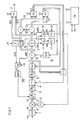
- Fig. 1 shows an exemplary circuit arrangement in which a received analog received signal sa is input as an initiating component to an analog / digital converter A / D, to which a clock signal t is applied.
- the analog / digital converter A / D converts the analog received signal sa into a digitized or digital signal sd.
- the digital signal sd is output to a quadrature converter or mixer 1, which converts the digitized or digital signal sd into baseband and splits it onto the quadrature components of the quadrature signal pair I, Q.
- the signal output from the mixer 1 is applied to an amplifier control device 2 in a manner known per se.
- a signal amplified by the gain controller 2 is supplied to a low-pass filter 3, the output of which is supplied to a sampling device 4 at which a sampling clock ti is applied for sampling.
- a signal sampled with the sampling device 4 is output to a further low-pass filter 5 as a Nyquist filter and filtered by it and applied to an equalizer EQ (German: equalizer).
- the equalizer EQ outputs received signal values or received symbols S to a rotator 6, to which an estimated phase rotation angle -p is additionally applied.
- an estimated phase rotation angle -p By means of the estimated phase rotation angle -p, a sequence is generated from the received symbols S by a corresponding rotation with the estimated phase rotation angle by the respectively estimated phase rotation angle -p corrected rotated received symbols Sr and output by the rotator 6.
- the rotated received symbols Sr are applied both to a first decider 7, which effects a decision on the basis of Cartesian coordinates, and to a second or further decider 8, which makes a decision based on, in particular, polar coordinates.
- the first decision maker 7 decides, in accordance with the respectively applied rotated received symbol Sr, a phase-correcting rotated and Cartesian decided symbol Dr1 and outputs it.
- the second decider 8 generates a phase-correcting rotated and polar decided second symbol Dr2 corresponding to the respective rotated rotated received symbol Sr, and outputs it.
- a decision maker may in particular be used for the polar decision, which first performs a Cartesian auxiliary decision and thereby selects a large number of adjacent receiving points as candidates for a final decision. Thereafter, in the second decision maker thus constructed, the radius and phase errors are calculated for each candidate and weighted according to optionally applicable current settings. The point with the lowest weighted error is then output as a decided second symbol Dr2. Ideally, in such a second decider 8, the weighted errors for all possible receiving points are calculated to select the best point, but also a limited number of adjacent points for estimating the decided second symbol Dr2 can be considered to reduce the computational burden.
- the rotation can be done by a simple angle addition in polar coordinates.
- the decided by the two decision makers 7, 8 phase correcting, decided symbols Dr1, Dr2 are applied to a switch X1, which outputs a decided symbol D.
- the decided symbol D is output to further circuitry for further data processing, as is known per se.
- the phase-correcting rotated and Cartesian decided first symbol Dr1 of the first decider 7 or alternatively the phase-corrected rotated and polar decided second symbol Dr2 of the second decider are output as the decided symbol D.
- the data or decided symbols D output in this way can, for example, be further processed in an error correction block.
- the changeover in the changeover switch X1 is effected by a control signal c1, which is output by a control device CU.
- the control device CU is advantageously an integral part of the circuit arrangement, but in principle can also be implemented by an external control device.
- phase-corrected and Cartesian polar first and second symbols Dr1, Dr2 are also respectively applied to a further rotator 9 and 10, respectively, which perform a reverse rotation about the estimated phase rotation angle p and correspondingly a Cartesian back-rotated or non-phase-corrected first decided symbol D1 or output a polar turned back or not phase-corrected second decided symbol D2.
- the two turned back symbols D1, D2 are both applied to a further switch and / or mixer X2, which is additionally applied by the control device CU, a corresponding control signal c2.
- a further switch and / or mixer X2 which is additionally applied by the control device CU, a corresponding control signal c2.
- the clock control symbol Dt or a corresponding sequence of the clock control symbols Dt is in a manner known per se for further processing a correlator CC for determining the symbol rate and symbol phase for controlling the analog / digital converter and / or a sampling rate converter or the sampling device 4 created.
- the sequence CC of the received symbols S is also applied to the correlator CC in a manner known per se.
- the correlator CC corresponding to and the sampling clock ti is generated and applied to the analog / digital converter A / D or to the sampling device 4.
- the clock signal ti may also control the analog-to-digital converter A / D, in which case the sampling rate conversion in the scanner 4 is not required.
- the two turned back symbols D1, D2 are also applied to another switch and / or mixer X3.
- a control signal CU provided by the further control signal c3, which is applied to this switch and / or mixer X3, according to the signal state, a switching or mixing of the two turned back symbols D1, D2 for generating the equalizer control symbol De for further processing in the equalizer EQ both for generating an error voltage for a so-called feed-forward equalizer and a decision feedback equalizer as well as for the necessary decided symbols for the decision feedback equalizer carried out.
- an equalizer control symbol De is accordingly provided for controlling the equalizer EQ as a function of the control signal c3 and the two applied Cartesian or polarly turned back symbols D1 and D2.
- the first decision maker 7 also provides a Cartesian decided in the first decision maker 7 phase error ⁇ 1 between the currently applied rotated received symbol Sr and the phase-corrected rotated and Cartesian decided Dr1 symbol.
- the second decider 9 also provides a polar phase error .DELTA..phi.2 decided in the first decider 7 between the instantaneously rotated rotated received symbol Sr and the symbol Dr2 rotated therefrom in a phase correcting manner and decided Cartesian.
- the two decided phase errors ⁇ 1, ⁇ 2 are applied to yet another switch and / or mixer X4.
- this switch and / or mixer performs a switching or mixing of the phase errors ⁇ 1, ⁇ 2 or the decided phases and outputs a selected phase difference ⁇ p for a phase locked loop.
- the selected phase difference ⁇ p is applied for further processing to a phase control module PC, which is controlled by a further control signal c7 via the control device CU.
- the phase control module PC is used to define or provide the coefficients of the plausibility filter for controlling the tilt or phase rotation angle p. As described, the phase rotation angle p is used to rotate the received symbols S and to reverse the decided symbols Dr1, Dr2, respectively.
- the selected phase difference ⁇ p is thus used for further processing in a block for the phase rotation of the signals or symbols S before the deciders 7, 8 and for a counter-rotation of the decided symbols Dr1, Dr2 or the error voltages from the deciders 7, 8 regardless of whether the rotator 6 is in front of or behind a Nyquist filter, the feed-forward equalizer or the decision feedback equalizer.
- This is also independent of whether the counter-rotator or counter rotators are located before or after the aforementioned switches or mixers X2, X3, and regardless of whether decided symbols or equivalent error voltages are rotated.
- the two Cartesian or polar decided phase error ⁇ 1, ⁇ 2 are additionally applied to another switch and / or mixer X5, which is controlled by the control device CU by means of a further control signal c5.
- switching or mixing of the two Cartesian or polar decided phase errors ⁇ 1, ⁇ 2 or, equivalently, of the decided phases is brought about by the control signal c5 and correspondingly a selected frequency difference ⁇ f is output for a frequency control loop.
- the selected frequency difference ⁇ f is applied to a frequency control module FC, which provides a control signal for a local oscillator LO.
- the local oscillator LO outputs two carriers offset by 90 ° to the mixer 1, so that the mixer 1 receives the digital signal sd to provide the two quadrature components I, Q.
- the control of the frequency control module FC is effected by a further control signal c8 via the control device CU.
- This control signal c8 effects a control of the parameters of the frequency control block or frequency control module FC, in particular a control of the filter coefficients of a built-in PI filter for controlling the frequency of the local oscillator LO.
- the first decider 7 also outputs a first radii error ⁇ R1 decided in the Cartesian decider 7 as the difference between the magnitudes of the rotated received signal Sr and the symbol Dr1 decided by the first decider 7. Accordingly, the second decision 8 gives a second, in this polar decided radius error as a difference of the amounts of the received rotated symbol Sr and decided by the second decider 8 symbol Dr2.
- the two decided radius errors ⁇ R1, ⁇ R2 are applied to another switch and / or mixer X6.
- this switch and / or mixer X6 emits a radius error ⁇ R by switching or mixing the two decided radii errors ⁇ R1, ⁇ R2 or equivalently correspondingly decided radii for further processing in a circuit for regulating the amplitude.
- this change-over switch and / or mixer outputs the radii error ⁇ R obtained by switching or mixing to an amplitude correction module 20 which, for example, performs an automatic gain control or AGC control by a corresponding provision of a control signal for the gain control device 2.
- control device CU also outputs a further control signal c9, which is applied thereto for controlling the parameters of the second decoder 8, which also acts in the polar coordinate system.
- a control is effected, in particular, of the addition ratio of the phase error ⁇ and of the radius error ⁇ R on which the distance decision is based as well as possibly an admixture of Cartesian deviations.
- the controller CU may be equipped or programmed with a table or with various tables for the various blocks to be controlled, with an equation that determines the ratio of Gaussian noise to phase noise, with many such equations, or with a combination of such means.
- the control parameters or control signals c1, c2,..., C9 of the control device CU can be provided simultaneously or independently of one another and correspondingly simultaneously or independently of one another the respectively controlled components drive.
- the control signals c1, ..., c9 may each provide two positions for Gaussian noise or more preferably even more positions.
- a control signal c1,..., C9 can also be provided for the corresponding components or mixers, which advantageously permits continuous regulation.
- Such a circuit arrangement can be used in particular in conjunction with complex digital modulation methods such as QAM.
- Applications arise in particular in the context of recent broadcasting, television and data services via cable and partly also via terrestrial transmissions.
- circuit arrangement which is preferably used as an independent component of a receiver
- all critical functional blocks and modules are designed and / or programmed so that the best possible receiver parameters are adjustable for each noise combination. This happens as a function of the phase noise PN and the measure of the Gaussian noise GN.
- the more setting options are provided with particular small increments or continuous adjustability for each of the control blocks, etc., the better a decision of symbols in the limit range of just possible reception at a predetermined ratio of the phase noise PN and the Gaussian noise GN can be exploited ,
- Fig. 2 schematically illustrates reception limits with different parameter sets at different ratios of Gaussian noise GN to phase noise PN.
- An optimal one Parameter set for Gaussian noise is shown in dashed lines.
- Measurement results of the Gaussian noise GN and the phase noise PN are as in Fig. 3 sketched, the control device CU supplied, which in turn the parameters or control signals c1, ..., c9 for the various receiving blocks of the circuit according to Fig. 1 and optionally generates further control signals.
- the control device CU thus receives measured values, in particular those resulting from radius and amplitude deviations by the decision by means of the polar decoder.
- Fig. 4 illustrates set radii in the Cartesian plane of the quadrature signal pair Q, I with symbol positions on set radii. It can be seen that, when viewed in polar coordinates, the phase error or the angular deviation ⁇ does not produce an amplitude error and the amplitude error ⁇ R or its measured value or measured value gn is a good indicator of Gaussian noise GN.
- the angle deviation ⁇ or its measured value pn can be used.
- the measured variable pn is influenced by the additive noise or Gaussian noise GN.
- Exemplary weighting factors are assigned to the respective setpoint positions, whereby, for example, an innermost symbol with the factor 0 and a symbol on the outer radii with a factor of 4 are weighted.
- Such a multiplication of the error voltages with symbol- or radius-dependent values can again be carried out on the basis of values of a corresponding table.
- phase rotation angle p which represents the tilt of the decision system's coordinate system to that of the input signal
- the phase rotation angle p is simply the integration of the angular deviation ⁇ .
- angle differences for the integral can after EP 1 523 146 be used.
- phase rotation angle p is applied to a series circuit of delay elements 12, which each cause a preferably larger or in particular adjustable delay z -n .
- the input and the output of each of the delay elements 12 is connected to a respective associated subtraction element 13 to determine the difference of the input and output values of each of the delay elements 12. The differences are each applied by the subtraction elements 13 to an amount-forming element 14 for the formation of their amount.
- the magnitude values thus formed are added by means of an adder 15 or a chain of adders 15 to determine a measure pn for the phase noise PN. This is applied via a low-pass filter 16 of the control device CU, which additionally receives a corresponding amplitude error .DELTA.R2 from the likewise second decision maker 8.
- control device CU or a corresponding other suitable circuit can orthogonalize the two measured values by subtraction, in particular by solving a linear system of equations.
- Fig. 6 shows by way of example a representation of the Gaussian noise GN over the phase noise PN.
- the measured value pn for the phase noise PN of a symbol S lies on the abscissa, which represents the proportion of the general phase noise PN of a received symbol.
- a measured value gn for Gaussian noise of the symbol S up to a line connecting the two axes as a theoretical reception limit rg is shown. It can be seen that the Gaussian noise also causes the phase noise indicator to respond. Orthogonalization generates correspondingly independent indicators.
- the measured quantities of several consecutive symbols S can be used.
- variables derived from the measured quantities of a symbol S can also be used, such as the radius error ⁇ R, the absolute differences of the tilt obtained from plausible angular deviations or the phase rotation angle p between large delays z -1 and the radius-weighted angle deviations ⁇ .
- the remaining or high-frequency components of the amplitude fluctuations or the phase fluctuations are preferably used.
- the measured values gn and pn thus obtained are not completely independent of each other.
- the measurement of the amplitude fluctuation as a measured value gn for the Gaussian noise GN are not affected by a phase noise PN, the measurement of the phase fluctuations or angle deviations can very well be caused by Gaussian noise GN.
Landscapes
- Engineering & Computer Science (AREA)
- Computer Networks & Wireless Communication (AREA)
- Signal Processing (AREA)
- Digital Transmission Methods That Use Modulated Carrier Waves (AREA)
Applications Claiming Priority (1)
| Application Number | Priority Date | Filing Date | Title |
|---|---|---|---|
| DE102007056490A DE102007056490A1 (de) | 2007-11-22 | 2007-11-22 | Verfahren und Schaltungsanordnung zum Entscheiden eines Symbols beim Empfang von mit einem Quadratursignalpaar gekoppelten empfangenen Symbolen |
Publications (2)
| Publication Number | Publication Date |
|---|---|
| EP2063597A2 true EP2063597A2 (fr) | 2009-05-27 |
| EP2063597A3 EP2063597A3 (fr) | 2010-09-08 |
Family
ID=40430169
Family Applications (1)
| Application Number | Title | Priority Date | Filing Date |
|---|---|---|---|
| EP08019824A Withdrawn EP2063597A3 (fr) | 2007-11-22 | 2008-11-13 | Procédé et dispositif de commutation destinés à la décision d'un symbole lors de la réception de symboles reçus couplés à une paire de signaux de quadrature |
Country Status (3)
| Country | Link |
|---|---|
| US (1) | US8755467B2 (fr) |
| EP (1) | EP2063597A3 (fr) |
| DE (1) | DE102007056490A1 (fr) |
Cited By (2)
| Publication number | Priority date | Publication date | Assignee | Title |
|---|---|---|---|---|
| WO2016202745A1 (fr) * | 2015-06-18 | 2016-12-22 | Robert Bosch Gmbh | Dispositif et procédé pour vérifier la plausibilité d'un signal d'excitation pour un capteur d'angle de rotation |
| CN115208392A (zh) * | 2022-06-01 | 2022-10-18 | 中星联华科技(北京)有限公司 | 相位噪声控制方法、装置及系统 |
Families Citing this family (4)
| Publication number | Priority date | Publication date | Assignee | Title |
|---|---|---|---|---|
| DE10344756A1 (de) * | 2003-09-25 | 2005-05-12 | Micronas Gmbh | Verfahren und Schaltungsanordnung zum Entscheiden eines Symbols im komplexen Phasenraum eines Quadraturmodulationsverfahrens |
| US9140750B2 (en) | 2009-10-21 | 2015-09-22 | Advantest Corporation | Apparatus comprising a recursive delayer and method for measuring a phase noise |
| US9423440B2 (en) * | 2009-10-21 | 2016-08-23 | Advantest Corporation | Test device and test method for measuring a phase noise of a test signal |
| WO2023006432A1 (fr) | 2021-07-29 | 2023-02-02 | St Engineering Idirect (Europe) Cy Nv | Procédé d'estimation de bruit de phase |
Citations (3)
| Publication number | Priority date | Publication date | Assignee | Title |
|---|---|---|---|---|
| EP1201066B1 (fr) | 2000-04-17 | 2003-09-10 | Atmel Corporation | Estimation de bruit de phase et de bruit additif dans un circuit de recuperation de porteuse a modulation d'amplitude en quadrature (maq) |
| EP1523146A2 (fr) | 2003-10-08 | 2005-04-13 | Micronas GmbH | Procédé pour la synchonisation d'un circuit lors de la réception d'un signal modulé |
| EP1523144A2 (fr) | 2003-09-25 | 2005-04-13 | Micronas GmbH | Procédé et circuit de détermination d'un symbole dans l'espace complexe de phase d'un procédé de modulation en quadrature |
Family Cites Families (6)
| Publication number | Priority date | Publication date | Assignee | Title |
|---|---|---|---|---|
| US4827431A (en) * | 1987-01-20 | 1989-05-02 | General Datacomm, Inc. | Methods and systems for the simultaneous quantitative measurement of phase and amplitude jitter impairments and signal to noise ratio in a qam data communication channel |
| FR2824977A1 (fr) * | 2001-05-15 | 2002-11-22 | France Telecom | Procede de demodulation et de modulation d'un signal tenant compte de l'effet d'erreurs de phase, recepteur, systeme et signal correspondants |
| US7088978B2 (en) * | 2003-02-07 | 2006-08-08 | Ericsson Inc. | System and method for interference cancellation in a wireless communication receiver |
| US7668269B2 (en) * | 2005-05-09 | 2010-02-23 | Ati Technologies, Inc. | Systems, methods, and apparatus for phase noise mitigation |
| DE102006008494B4 (de) * | 2006-02-23 | 2010-01-28 | Rohde & Schwarz Gmbh & Co. Kg | Verfahren zur Phasenrauschkompensation und entsprechender Messempfänger |
| US20080123788A1 (en) * | 2006-11-29 | 2008-05-29 | Supat Wongwirawat | Method and apparatus for detecting and correcting modulated signal impairments |
-
2007
- 2007-11-22 DE DE102007056490A patent/DE102007056490A1/de not_active Ceased
-
2008
- 2008-11-13 EP EP08019824A patent/EP2063597A3/fr not_active Withdrawn
- 2008-11-21 US US12/276,023 patent/US8755467B2/en not_active Expired - Fee Related
Patent Citations (3)
| Publication number | Priority date | Publication date | Assignee | Title |
|---|---|---|---|---|
| EP1201066B1 (fr) | 2000-04-17 | 2003-09-10 | Atmel Corporation | Estimation de bruit de phase et de bruit additif dans un circuit de recuperation de porteuse a modulation d'amplitude en quadrature (maq) |
| EP1523144A2 (fr) | 2003-09-25 | 2005-04-13 | Micronas GmbH | Procédé et circuit de détermination d'un symbole dans l'espace complexe de phase d'un procédé de modulation en quadrature |
| EP1523146A2 (fr) | 2003-10-08 | 2005-04-13 | Micronas GmbH | Procédé pour la synchonisation d'un circuit lors de la réception d'un signal modulé |
Cited By (3)
| Publication number | Priority date | Publication date | Assignee | Title |
|---|---|---|---|---|
| WO2016202745A1 (fr) * | 2015-06-18 | 2016-12-22 | Robert Bosch Gmbh | Dispositif et procédé pour vérifier la plausibilité d'un signal d'excitation pour un capteur d'angle de rotation |
| US10989572B2 (en) | 2015-06-18 | 2021-04-27 | Robert Bosch Gmbh | Apparatus and method for checking the plausibility of an excitation signal for a rotary encoder |
| CN115208392A (zh) * | 2022-06-01 | 2022-10-18 | 中星联华科技(北京)有限公司 | 相位噪声控制方法、装置及系统 |
Also Published As
| Publication number | Publication date |
|---|---|
| US20090135967A1 (en) | 2009-05-28 |
| EP2063597A3 (fr) | 2010-09-08 |
| DE102007056490A1 (de) | 2009-05-28 |
| US8755467B2 (en) | 2014-06-17 |
Similar Documents
| Publication | Publication Date | Title |
|---|---|---|
| DE68926583T2 (de) | Interferenzunterdrückungsschaltung | |
| DE69007505T2 (de) | Verfahren zur schnellen Einstellung der Frequenz eines kohärenten Radioempfängers und Gerät zur Durchführung des Verfahrens. | |
| EP2063597A2 (fr) | Procédé et dispositif de commutation destinés à la décision d'un symbole lors de la réception de symboles reçus couplés à une paire de signaux de quadrature | |
| DE2646255A1 (de) | Digitales detektorsystem fuer differentielle phasenshift-umtastsignale | |
| DE3741698A1 (de) | Empfaenger fuer radiowellen mit mehreren antennen | |
| DE4013384A1 (de) | Empfaenger mit einer anordnung zur frequenzablagenschaetzung | |
| DE3510580A1 (de) | Verfahren und schaltungsanordnung zur verbesserung des empfangs von radiowellen | |
| DE2656924C3 (de) | Phasendiskriminator in einem Empfänger eines Datenübertragungssystems | |
| EP1592164B1 (fr) | Procédé et circuit pour déterminer un point d'échantillonnage par un signal d'horloge pour des symboles d'un procédé de modulation | |
| DE69729329T2 (de) | Gerät und verfahren zur phasenschätzung | |
| DE2556959B2 (de) | Automatischer Bandpassentzerrer für Datenübertragungssysteme | |
| DE3490533T1 (de) | Diversity-Kombinator | |
| DE102008054153A1 (de) | Sender und Empfänger mit mehreren Filtern | |
| DE19934215C1 (de) | Quadraturmischer mit adaptiver Fehlerkompensation | |
| DE3938643C2 (de) | Verfahren zum Rekonstruieren abgetrennter Gleichspannungsnutzanteile an ZF-Signalen in einem Direct-Conversion-Empfänger und Empfänger zum Durchführen des Verfahrens | |
| DE102006005032A1 (de) | Empfangsverfahren mit digitaler Pegeleinstellung im Analogteil und stufenweiser Pegelveränderung im Digitalteil | |
| DE102010027166B4 (de) | Positionsmessvorrichtung und Verfahren zur Positionsmessung mittels Hall-Sensoren | |
| DE60035559T2 (de) | Verfahren zum Vergleichen der Amplituden von zwei elektrischen Signalen | |
| EP1892910A2 (fr) | Procédé ou circuit destiné à déterminer un symbole lors de la réception d'un signal coupé avec une paire de signaux à quadrature | |
| EP0602394A2 (fr) | Procédé et dispositif de correction des erreurs de phase et d'amplitude pour des dispositifs récepteurs à conversion directe | |
| DE10360470B4 (de) | Verfahren und Vorrichtung zum Demodulieren eines Empfangssignals | |
| DE10213423A1 (de) | Schaltungsanordnung zum Schieben der Phase eines Eingangssignals und Schaltungsanordnung zur Spiegelfrequenzunterdrückung | |
| DE4340012A1 (de) | Demodulator | |
| DE2443870A1 (de) | Einstellung eines empfangstaktgebers | |
| DE102008010254B4 (de) | Empfangsschaltung und Verfahren zum Empfangen eines Signals einer Amplitudenumtastung |
Legal Events
| Date | Code | Title | Description |
|---|---|---|---|
| PUAI | Public reference made under article 153(3) epc to a published international application that has entered the european phase |
Free format text: ORIGINAL CODE: 0009012 |
|
| AK | Designated contracting states |
Kind code of ref document: A2 Designated state(s): AT BE BG CH CY CZ DE DK EE ES FI FR GB GR HR HU IE IS IT LI LT LU LV MC MT NL NO PL PT RO SE SI SK TR |
|
| AX | Request for extension of the european patent |
Extension state: AL BA MK RS |
|
| RAP1 | Party data changed (applicant data changed or rights of an application transferred) |
Owner name: TRIDENT MICROSYSTEMS (FAR EAST) LTD. |
|
| PUAL | Search report despatched |
Free format text: ORIGINAL CODE: 0009013 |
|
| AK | Designated contracting states |
Kind code of ref document: A3 Designated state(s): AT BE BG CH CY CZ DE DK EE ES FI FR GB GR HR HU IE IS IT LI LT LU LV MC MT NL NO PL PT RO SE SI SK TR |
|
| AX | Request for extension of the european patent |
Extension state: AL BA MK RS |
|
| 17P | Request for examination filed |
Effective date: 20110307 |
|
| AKX | Designation fees paid |
Designated state(s): DE FR GB |
|
| RAP1 | Party data changed (applicant data changed or rights of an application transferred) |
Owner name: ENTROPIC COMMUNICATIONS, INC. |
|
| GRAP | Despatch of communication of intention to grant a patent |
Free format text: ORIGINAL CODE: EPIDOSNIGR1 |
|
| INTG | Intention to grant announced |
Effective date: 20161108 |
|
| STAA | Information on the status of an ep patent application or granted ep patent |
Free format text: STATUS: THE APPLICATION IS DEEMED TO BE WITHDRAWN |
|
| 18D | Application deemed to be withdrawn |
Effective date: 20170321 |