EP2063774B1 - Procédé et système de mesure non invasive de paramètres cardiaques - Google Patents
Procédé et système de mesure non invasive de paramètres cardiaques Download PDFInfo
- Publication number
- EP2063774B1 EP2063774B1 EP07805548.0A EP07805548A EP2063774B1 EP 2063774 B1 EP2063774 B1 EP 2063774B1 EP 07805548 A EP07805548 A EP 07805548A EP 2063774 B1 EP2063774 B1 EP 2063774B1
- Authority
- EP
- European Patent Office
- Prior art keywords
- cardiac
- individual
- data
- ohm
- impedance change
- Prior art date
- Legal status (The legal status is an assumption and is not a legal conclusion. Google has not performed a legal analysis and makes no representation as to the accuracy of the status listed.)
- Not-in-force
Links
Images


Classifications
-
- A—HUMAN NECESSITIES
- A61—MEDICAL OR VETERINARY SCIENCE; HYGIENE
- A61B—DIAGNOSIS; SURGERY; IDENTIFICATION
- A61B5/00—Measuring for diagnostic purposes; Identification of persons
- A61B5/02—Detecting, measuring or recording for evaluating the cardiovascular system, e.g. pulse, heart rate, blood pressure or blood flow
- A61B5/02028—Determining haemodynamic parameters not otherwise provided for, e.g. cardiac contractility or left ventricular ejection fraction
-
- A—HUMAN NECESSITIES
- A61—MEDICAL OR VETERINARY SCIENCE; HYGIENE
- A61B—DIAGNOSIS; SURGERY; IDENTIFICATION
- A61B5/00—Measuring for diagnostic purposes; Identification of persons
- A61B5/02—Detecting, measuring or recording for evaluating the cardiovascular system, e.g. pulse, heart rate, blood pressure or blood flow
- A61B5/02028—Determining haemodynamic parameters not otherwise provided for, e.g. cardiac contractility or left ventricular ejection fraction
- A61B5/02035—Determining blood viscosity
-
- A—HUMAN NECESSITIES
- A61—MEDICAL OR VETERINARY SCIENCE; HYGIENE
- A61B—DIAGNOSIS; SURGERY; IDENTIFICATION
- A61B5/00—Measuring for diagnostic purposes; Identification of persons
- A61B5/02—Detecting, measuring or recording for evaluating the cardiovascular system, e.g. pulse, heart rate, blood pressure or blood flow
- A61B5/0205—Simultaneously evaluating both cardiovascular conditions and different types of body conditions, e.g. heart and respiratory condition
-
- A—HUMAN NECESSITIES
- A61—MEDICAL OR VETERINARY SCIENCE; HYGIENE
- A61B—DIAGNOSIS; SURGERY; IDENTIFICATION
- A61B5/00—Measuring for diagnostic purposes; Identification of persons
- A61B5/02—Detecting, measuring or recording for evaluating the cardiovascular system, e.g. pulse, heart rate, blood pressure or blood flow
- A61B5/021—Measuring pressure in heart or blood vessels
-
- A—HUMAN NECESSITIES
- A61—MEDICAL OR VETERINARY SCIENCE; HYGIENE
- A61B—DIAGNOSIS; SURGERY; IDENTIFICATION
- A61B5/00—Measuring for diagnostic purposes; Identification of persons
- A61B5/02—Detecting, measuring or recording for evaluating the cardiovascular system, e.g. pulse, heart rate, blood pressure or blood flow
- A61B5/026—Measuring blood flow
- A61B5/029—Measuring blood output from the heart, e.g. minute volume
-
- A—HUMAN NECESSITIES
- A61—MEDICAL OR VETERINARY SCIENCE; HYGIENE
- A61B—DIAGNOSIS; SURGERY; IDENTIFICATION
- A61B5/00—Measuring for diagnostic purposes; Identification of persons
- A61B5/02—Detecting, measuring or recording for evaluating the cardiovascular system, e.g. pulse, heart rate, blood pressure or blood flow
- A61B5/026—Measuring blood flow
- A61B5/0295—Measuring blood flow using plethysmography, i.e. measuring the variations in the volume of a body part as modified by the circulation of blood therethrough, e.g. impedance plethysmography
-
- A—HUMAN NECESSITIES
- A61—MEDICAL OR VETERINARY SCIENCE; HYGIENE
- A61B—DIAGNOSIS; SURGERY; IDENTIFICATION
- A61B5/00—Measuring for diagnostic purposes; Identification of persons
- A61B5/05—Detecting, measuring or recording for diagnosis by means of electric currents or magnetic fields; Measuring using microwaves or radio waves
- A61B5/053—Measuring electrical impedance or conductance of a portion of the body
-
- A—HUMAN NECESSITIES
- A61—MEDICAL OR VETERINARY SCIENCE; HYGIENE
- A61B—DIAGNOSIS; SURGERY; IDENTIFICATION
- A61B5/00—Measuring for diagnostic purposes; Identification of persons
- A61B5/24—Detecting, measuring or recording bioelectric or biomagnetic signals of the body or parts thereof
- A61B5/25—Bioelectric electrodes therefor
- A61B5/251—Means for maintaining electrode contact with the body
-
- A—HUMAN NECESSITIES
- A61—MEDICAL OR VETERINARY SCIENCE; HYGIENE
- A61B—DIAGNOSIS; SURGERY; IDENTIFICATION
- A61B5/00—Measuring for diagnostic purposes; Identification of persons
- A61B5/24—Detecting, measuring or recording bioelectric or biomagnetic signals of the body or parts thereof
- A61B5/25—Bioelectric electrodes therefor
- A61B5/276—Protection against electrode failure
-
- A—HUMAN NECESSITIES
- A61—MEDICAL OR VETERINARY SCIENCE; HYGIENE
- A61B—DIAGNOSIS; SURGERY; IDENTIFICATION
- A61B5/00—Measuring for diagnostic purposes; Identification of persons
- A61B5/24—Detecting, measuring or recording bioelectric or biomagnetic signals of the body or parts thereof
- A61B5/25—Bioelectric electrodes therefor
- A61B5/279—Bioelectric electrodes therefor specially adapted for particular uses
- A61B5/28—Bioelectric electrodes therefor specially adapted for particular uses for electrocardiography [ECG]
-
- A—HUMAN NECESSITIES
- A61—MEDICAL OR VETERINARY SCIENCE; HYGIENE
- A61B—DIAGNOSIS; SURGERY; IDENTIFICATION
- A61B5/00—Measuring for diagnostic purposes; Identification of persons
- A61B5/24—Detecting, measuring or recording bioelectric or biomagnetic signals of the body or parts thereof
- A61B5/316—Modalities, i.e. specific diagnostic methods
-
- A—HUMAN NECESSITIES
- A61—MEDICAL OR VETERINARY SCIENCE; HYGIENE
- A61B—DIAGNOSIS; SURGERY; IDENTIFICATION
- A61B5/00—Measuring for diagnostic purposes; Identification of persons
- A61B5/24—Detecting, measuring or recording bioelectric or biomagnetic signals of the body or parts thereof
- A61B5/316—Modalities, i.e. specific diagnostic methods
- A61B5/318—Heart-related electrical modalities, e.g. electrocardiography [ECG]
- A61B5/339—Displays specially adapted therefor
- A61B5/341—Vectorcardiography [VCG]
-
- A—HUMAN NECESSITIES
- A61—MEDICAL OR VETERINARY SCIENCE; HYGIENE
- A61B—DIAGNOSIS; SURGERY; IDENTIFICATION
- A61B5/00—Measuring for diagnostic purposes; Identification of persons
- A61B5/02—Detecting, measuring or recording for evaluating the cardiovascular system, e.g. pulse, heart rate, blood pressure or blood flow
- A61B5/024—Measuring pulse rate or heart rate
Definitions
- the present invention is generally in the field of cardiology. More specifically, the invention concerns non-invasive techniques for measuring and monitoring the main hemodynamic parameters of a patient, such as cardiac parameters, utilizing body bioimpedance techniques.
- Measurement of cardiac output is a basic diagnostic and therapeutic requirement in the management of patients with cardiac conditions.
- the indicator for Fick is oxygen, thermodilution uses cold saline or dextrose, dye dilution uses cardiogreen, and they are all invasive techniques that require specialist expertise and expensive capital equipment, can be employed only on hospital premises, and all pose a certain risk.
- Electrodes are applied to the root of the neck and to the lower part of the thorax, and the chest is measured as an electrical field.
- the method was first suggested in 1964 [ Patterson et al., Proc. 1st Annu Rocky Mt. Bioeng. Sympos., 1964, 56-71 ] and was upgraded in 1974 [ Kubicek et al. Biomed. Eng. 1974, 9:410-16 ] where the ⁇ R parameter was replaced by its first derivative, the dR/dt, of the impedance change, multiplied by the ejection time (T), for the stroke volume calculation.
- the sources of errors in TIC established by experimental and clinical data include the following: (1) individual anatomical differences in the position of organs in the thorax cage; (2) non-linear changes of the electrical resistivity of the flowing blood; (3) the current electrodes position and the distance between the voltage electrodes; (4) the ejection pattern; (5) the outflow problem; (6) the influences of multifactors on the thoracic basal impedance value; (7) the inability to assess the contribution from the right heart and pulmonary circulation; and (8) the inability to assess impedance changes independently of volume changes, such as mechanical displacements of the heart and great vessels.
- the accuracy of the ICG WB technique is higher than that of the TIC due to the fact that the peripheral systolic impedance changes are more reliable signals for calculating the stroke volume than the thoracic systolic impedance waveforms.
- this technology is cumbersome, and in many clinical conditions the extremities are used for invasive IV or IA procedures such as intra-arterial pressure monitoring, IV treatment, etc. Movement artifacts also increase due to the use of multiple electrodes. All these factors make it difficult or impractical to use these methods in clinical conditions.
- This technique utilizes two pairs of electrodes, one pair of electrodes being applied to one wrist and the other pair of electrodes - to the contralateral ankle.
- this method is called regional impedance cardiography (RIC).
- RIC regional impedance cardiography
- This technique was approbated in cardiac surgery clinics in 1998 by Cohen et al. [Eur J Cardiothorac Surg 1998; 14:64-9 ]; Cotter et al., Accurate, noninvasive continuous monitoring of cardiac output by whole-body electrical bioimpedance, Chest. 2004 Apr;125(4): 1431-40 ; Cotter et al, Impedance cardiography revisited. Physiol. Meas., 2006, 27:817-827 . Compared to TIC, the accuracy of RIC is higher by a factor of 2.
- RIC provides for increasing the accuracy of measurement by a factor of 2, it appears that this technique is not acceptable for a significant group of patients, approximately 15% ( Cotter et al, Impedance cardiography revisited. Physiol. Meas., 2006, 27:817-827 ).
- the present invention provides a solution for the above, and is based on the understanding of the well-established biophysical and physiological data of the interaction of the conductivity changes of the flowing blood with electrical resistance changes caused by the arterial wall expansion during the cardiac cycle ( Ninomiya M, et al, Physical properties of flowing blood. Biorheology, 1988,25(1-2):319-28 ; Visser et al, Impedance cardiography and electrical properties of blood, Proceedings of the Vth ICEBI, Aug. 1981, Tokyo, pp. 13-16 ; Investigation of the origin of the impedance cardiogram by means of exchange transfusion with stroma free haemoglobin solution in the dog. Cardiovasc Res. 1990, Jan. 24(1):24-32 ; Wtorek et al, Relations between components of impedance cardiogram analyzed by means of finite element model and sensitivity theorem. Annals of Biomedical Engineering 2000; 28, 1352-61 ).
- the first source is conductivity changes due to volumetric changes of blood in the systolic expansion of arterial system during the cardiac cycle. Volumetric changes are precisely assessed by the volume ( ⁇ R) wave.
- the second source is conductivity changes due to conductivity changes of the flowing blood caused by erythrocytes orientation effect during the cardiac cycle. Conductivity changes caused by the flowing blood are precisely assessed by the blood flow velocity (dR/dt) wave.
- volumetric pulsatile changes ⁇ R
- dR/dt velocimetric pulsatile changes
- the inventors have recently discovered that to calculate the SV in patients with acute heart failure there is an advantage to the velocimetric formula. The reason for this is that in patients with acute heart failure there is an arterial peripheral vasoconstriction, with a reduction in the arterial wall distensibility ( Nieminen MS, Pharmacological options for acute heart failure syndromes. Current treatments and unmet needs. Eur Heart J 2005; 7(Suppl B):20-24 ).
- the inventors have found that under such circumstances, the volumetric formula underestimates thermodilution SV results.
- the maintenance of the required SV is achieved by a compensatory increase in the velocity of the systolic blood flow, leading to the better suitability of the dR/dt algorithm for calculating the SV in patients with acute heart failure.
- a method for use in assessment of at least one cardiac parameter of an individual comprising:
- the measured data is obtained as an electrical output from an electrodes arrangement on an individual's body (individual's extremities): the electrodes arrangement is adapted to apply an electrical field to the body and to provide an electrical output indicative of change during a cardiac cycle.
- the method is performed using a tetrapolar electrode arrangement.
- said providing of the electrodes arrangement comprises attaching two electrode units on two limbs of the individual, preferably on one wrist and on a contralateral ankle (e.g. leg-arm).
- the at least one cardiac parameter is selectively calculated based on the models utilizing two independent parameters, the ⁇ R / R volumetric parameter, and the ((dR / dt) ⁇ T) blood velocity parameter, using separate equations.
- the latter may be those of the known Frinerman formula (see US Patent No. 5,469,859 assigned to the assignee of the present application) and Patterson equation, respectively, or new versions of the same corrected by the inventors, as will be described below.
- Each model is 'activated' according to the subject's individual conditions, i.e. in accordance with the TPR and/or the CI.
- At least one cardiac parameter is selectively calculated based on a new combined approach (equation), according to which the calculation results are based either on the ⁇ R / R volumetric parameter, or the ((dR / dt) ⁇ T) blood velocity parameter, in accordance with the TPR and/or CI and/or AHF condition of the individual.
- the invention also provides an impedance measurement system for use in assessment of at least one cardiac parameter of an individual, the system comprising:
- the TPR data is calculated using the patient's blood pressure data BP and the measured systolic impendance change from the electrical output, where the cardiac output is calculated as a product of the measured stroke volume (calculated from the electrical output) and the heart rate, while the latter can be obtained form the ECG measurement or from the impedance wave.
- the invention also provides a control system for use with an impedance measurement system for assessment of at least one cardiac parameter of an individual, the control system comprising data input and output utilities and data processing and analyzing utility, and being configured and operable to: receive measured electrical output from an electrodes arrangement indicative of a systolic impedance change and of a velocity of said change during a cardiac cycle; determine at least one of the individual's total peripheral resistance (TPR), the individual's cardiac index (CI), and the existence of the AHF condition for identifying whether the TPR satisfies a first predetermined condition and/or the CI satisfies a second predetermined condition and/or the condition of AHF is identified; and process the measured electrical output by applying a predetermined model configured to selectively calculate said at least one cardiac parameter based on said data of the velocity of the impedance change or on the systolic impedance change data, if at least one of said conditions is satisfied or not, respectively.
- TPR total peripheral resistance
- CI the individual's
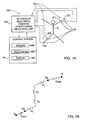
- Impedance measurement system 10A for use in assessment of at least one cardiac parameter of an individual (such as stroke volume, heart rate, cardiac output, cardiac index, etc.).
- Impedance measurement system 10A includes a measurement system 12 and a control system 18.
- Measurement system 12 includes an electrodes' arrangement 14 for attaching to individual's 5 extremities, and an electrical integral bioimpedance measuring unit 15A.
- system 10A is configured for the tetrapolar mode of operation.
- electrodes arrangement 14 is configured to define two pairs of electrodes, which in the present example is implemented by using four electrodes, E 1 -E 1 ' and E 2 -E 2 ' for applying a weak electrical current (e.g. about 0.5-2mA, e.g. 1.4mA) through the body and measuring an electrical output of the body.
- the electrical output is indicative of a systolic impedance change (volumetric change) and of a velocity of said change during a cardiac cycle.
- the first electrode unit E 1 -E 1 ' is applied to the patient's arm and the second electrode unit E 2 -E 2 ' is applied to the patient's leg.
- the electrodes are connected to electrical integral bioimpedance measuring unit 15A which is connectable (via wires or via wireless signal transmission) to control system 18.
- Fig. 1B shows an electrical scheme defined by the above configuration of the electrodes' arrangement. As shown, locations 3-3a and 4-4a of the two pairs of electrodes E 1 -E 1 ' and E 2 -E 2 ', respectively, define two impedance regions of the skin between the electrodes of each pair, Z skin , and the body impendance regions Z 1 , Z 2 , Z 3 and Z 4 .
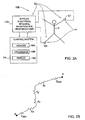
- Figs. 2A and 2B illustrate, respectively, an example of a measurement system 10B configured for the bipolar mode of operation utilizing an electrical integral bioimpedance measuring unit 15B, and an electrical scheme of such a system.
- the same reference numerals are used for identifying components that are common in all the examples of the invention.
- control system 18 is typically a computer system including inter alia data input and output utilities (not shown), memory utility 18A for storing reference data and a model data used for calculations, data processing and analyzing utility 18B, display 18C.
- the control system is preprogrammed to analyze the detected signal (electrical output), according to the method of the present invention.
- the control system is adapted to calculate the TPR utilizing the patient's blood pressure data BP and the measured systolic impedance change from the electrical output.
- the control system calculates the cardiac output as a product of the measured stroke volume (calculated from the electrical output) and the heart rate. The latter can be obtained from the ECG measurement or from the impedance wave.
- the control system then operates to analyze the TPR data, for determining whether the TPR satisfies a first predetermined condition, to thereby apply a predetermined model configured to selectively calculate said at least one cardiac parameter based on either the volumetric change data or on the velocimetric impedance data.
- Output data indicative of the calculation results is then generated and presented (e.g. displayed).
- the selective determination of the required parameter based on either the volumetric change data or on the velocimetric impedance data is associated with the following.
- the calculation of the left ventricular (LV) stroke volume (SV) by means of impedance cardiography (ICG) is based on two different physico-physiological principles, each of which can be independently used for measuring impedance changes of different origin which are incurred by the arterial pulsations.
- the first physico-physiological principle is based on the volumetric changes.
- This principle uses an algorithm based on the electrical signal of the systolic impedance variation (SIV) generated by the increase of the intra-arterial pulse volume.
- the basic variable in the respective formula of this algorithm is ⁇ R / R, multiplied by outflow decay ( ⁇ + ⁇ ) / ⁇ , where R is the value of basal resistance of the body (ohm), ⁇ R is the value of the SIV (Ohm), ⁇ and ⁇ are the systolic and diastolic time intervals, ( ⁇ + ⁇ ) being the time of a cardiac cycle, ⁇ being the descending part of the ⁇ R curve.
- the inventors have introduced such a correction hydration factor in order to correct the influence of the hydration state on the reliability of the stroke volume measurements.
- the hydration factor HF is dependent on a ratio between the measured total body water (TBW) volume and the expected individual's normal water volume.
- the actual TBW is measured as (4.96+0.42 L 2 /R) for women and (8.30 + 0.42 ⁇ L 2 /R) for men, where L is the individual's height and R is the measured resistance, and the TBW expected for the specific patient is typically determined as 40% - 63% of the body weight for the specific patient.
- HF is set as 1.0.
- the SV When a patient is dehydrated, which means that the measured TBW is below the above range, i.e. below 40% of the body weight, the SV would be decreased and thus needs to be corrected by the hydration factor, and similarly when the patient is over-hydrated, the measured TBW is higher than 63% of his weight, the SV would be increased and again needs to be corrected by the hydration factor.
- HF 1 TBW meas / BL
- TBW meas is the measured value of the patient's TBW and BL is the bottom limit of the normal TBW range
- HF 1 TBW meas / TL where TL is the top limit of the normal TBW range.
- equations (1) and (2) differ from each other in that the coefficient K sex age , which affects the basal resistance R, is represented in equation (2) by the corrected basal resistance R i , and the IB (index balance) is represented in equation (2) by the hydration factor HF.
- the corrected height H 2 corr is not included in equation (2), but in patients whose arms are disproportionately long the electrodes should preferably be placed about 5 cm proximally to their regular position.
- the invention utilizes the principal difference between the Hydration Factor and Index Balance consisting of the following:
- the hydration factor is the ⁇ R amplitude correction factor, while the index balance is used for assessment of patient's ideal R, prediction of which for extracellular body water included some irrelevant assumptions.
- the hydration factor is used only when the measured TBW for the specific patient is out of the normal range.
- the second physico-physiological principle is the velocimetric principle.
- the essence of this principle is the fact that the electrical signal of the SIV is determined by the systolic changes of the arterial blood velocity.
- the formula for the basic variable is dR / dt multiplied by the LV ejection time T .
- dR / dt is the peak of the first derivative of the blood resistance change during the cardiac cycle (ohm/sec)
- T is the cardiac ejection time (sec) namely the time interval between the point of the systolic upstroke of the maximal slope and the minimal point of the slope
- the parameter D being a distance between the electrodes in the Patterson equation is replaced by the height L of the patient
- a correcting coefficient k dr calibration factor
- the volumetric algorithms are used in ICG technologies where electrodes are applied peripherally to the limbs, and the velocimetric formula is used in the thoracic approach, where electrodes are applied to the chest.
- peripheral SIV signals is more accurate than that of thoracic SIV signals for calculating the stroke volume, and that in cases with normal values of total peripheral resistance (TPR) and of cardiac index (CI), the volumetric formula is preferable for measuring the SV, whereas in cases where TPR satisfies a first predetermined condition (is higher than a certain value within a range from about 1800 dynes ⁇ sec-cm -5 to about 1900 dynes ⁇ sec ⁇ cm -5 ), and preferably also when the CI satisfies a second predetermined condition (is lower than 2.5 lit/min/m 2 ), the velocimetric formula performs more accurately.
- a first predetermined condition is higher than a certain value within a range from about 1800 dynes ⁇ sec-cm -5 to about 1900 dynes ⁇ sec ⁇ cm -5
- a second predetermined condition is lower than 2.5 lit/min/m 2
- control system (its processing and analyzing utility) analyzes the data indicative of the patient's TPR and preferably also the CI, and decides about the model to be used for the SV calculation.
- the model may include separate formulas for the first and second principles underlying the calculation, namely, either one of formulas (1), (2) and (3), or formula (4a) or (4b), respectively.
- either one of the following parameters k HR and k dr is selectively set to value 1 or 0 depending on at least the measured individual's TPR, as described above.
- the new formula (5) uses both of the electrical impedance waveform physiological sources, namely conductivity changes due to volumetric changes of blood in the arterial system during cardiac cycle assessed by the volume ( ⁇ R) wave, and conductivity changes due to conductivity changes of the flowing blood caused by erythrocytes orientation effect during the cardiac cycle assessed by the blood flow velocity (dR/dt) wave.
- the technique of the present invention based on the selective use of the appropriate calculation mode, is grounded on the peripheral displacement of the minimum two electrodes to the individual's body in a manner enabling the acquisition of electrical bioimpedance measurements of the regional part of an individual's body.
- Using this technique advantageously provides the current dispersion throughout an individual's/subject's/patient's body and extremities, to be reduced.
- the measured resistance of a part of an individual's/subject's/patient's body is increased in comparison with whole-body resistance, thus increasing the accuracy of the measured R 0 and ⁇ R and dR/dt.
- the other two extremities of the patient are free for other possible treatments or measurements, or for patient's activities.
- the one or two extremities with local pathology may be excluded.
- the technique provides for body water and segmental body water distribution assessment.
- the present invention provides a novel system and method for calculating cardiac output through bioimpedance measurements of a patient.
- the system includes a bioimpedance measurement unit; electrodes' arrangement for attachment to a patient's arm and leg to provide an electrical output being in electrical communication with the resistance measurement unit; and a control system for operating the electrodes and for analyzing the electrical output.
- the invented technique for monitoring hemodynamic parameters is principally different from the existing systems in that the invented system includes a two-component (volumetric and velocimetric) approach providing a selective use of either one of the ⁇ R and dR / dt data, or possibly both of them, where ⁇ R ⁇ ( ⁇ + ⁇ ) / ⁇ and dR / dt ⁇ T are used interchangeably.
- the use of this novel approach preferably introduces a hydration factor for correction of ⁇ R value.
- the invention also provides for determining the hydration status of a patient by measuring the resistivity of the regional part of a patient's body and deriving the patient's hydration status.
- the resistivity of the interstitial fluid in the body is measured to derive the patient's hydration status.
- the patient's hydration state influences the amplitude and shape of the impedance waveform, as described above.
- the measurement/monitoring system of the present invention may be configured as a tetrapolar or bipolar electrical integral bioimpedance measurement system for measuring cardiovascular parameters.
- the tetrapolar mode is more accurate compared to the bipolar mode, because it excludes the influence of impedance between an electrode and a patient's skin.
- This impedance Z skin does not provide any useful information about the cardiovascular parameters of a patient;
- Z skin is an interference to body impedance and is influenced by the condition of the patient's skin (whether it is oily or dry, etc.).
- a human body behaves, from an electrical point of view, as a resistance-capacitance (RC) impedance.
- the value of impedance is influenced by the injection current frequency. This frequency is about 32KHz.
- the frequency of injecting current is controlled by a direct digital syntheser (DDS) generator 1 (which is a part of the measurement unit 15A in Fig. 1A ), which is in turn operated by a microcontroller 11.
- DDS direct digital syntheser
- the output frequency and amplitude of a sinusoidal signal are controlled to be stable. This signal operates a current source 2 (at the measurement unit 15A).
- the current source produces an electric current of the high-stability amplitude which is applied through two electrodes E 1 and E 2 at locations 3 and 4, respectively, to a patient's body 5. Also preferably provided in the measurement unit is a leadoff detector 17, which is used to sense the absence of a contact between the electrode and the body.
- the read voltage signal proportional to the human body impedance Z (i.e. an integral bioimpedance) is transferred from two voltage electrodes E' 1 and E' 2 at locations 3a and 4a respectively (+V, -V) to a high precision instrumentation amplifier 6, the output of which is fed to the first input of a synchronous detector 7.
- the latter has two functions: (1) it rectifies the obtained integral bioimpedance signal; and (2) it provides simultaneous derivation of the active component R of the integral bioimpedance signal vector. This component is directly proportional to the resistive component of the lead (resistance of the blood system). Linearity of the synchronous detector 7 simplifies the calibration process and reduces it to a single-step initial adjustment (instead of a per cycle calibration).
- the output of detector 7 is connected to a low frequency filter 8 which may for example be a low pass Bessel filter.
- Filter 8 cuts off high frequency components, for example above 32 KHz, and delivers an operating signal, which has the active bioimpedance component (DC) R, and the waveform bioimpedance signal (AC) ⁇ R.
- the operating signal is input to R Scale Amplifier 9 and to Bioamplifier and Filter 10.
- Amplifier 9 produces an output signal proportional to the active bioimpedance component R and transmits the same to an input ADC (Analog-to-Digital Converter) of the microcontroller 11.
- Bioamplifier and Filter 10 separates from the operating signal the waveform ⁇ R component.
- the output of the Bioamplifier and Filter 10 is connected to another input ADC of microcontroller 11.
- the latter communicates with a HOST processor (data processing and analyzing utility 18B of control system 18 in Fig. 1A ) which is not shown here.
- Fig. 3B further exemplifies the configuration of the measurement system of the invention.
- three additional ECG electrodes are used being applied to the chest of a patient and connected to an ECG measurement circuit 20.
- the measurement system includes a measurement unit (15A in Fig. 1A ) and a control system (18 in Fig. 1A ). The latter is represented in Fig. 3B by a HOST processor 21.
- the measurement unit includes a bioimpedance signal receiver unit 19 and a microcontroller 11 (such as model ADuC814 commercially available from Analog Device®), which combines the functions of an A/D converter and a microprocessor, and operates for real time processing of first data or curve (which is a composition of direct "R” and alternating " ⁇ R" components of an active bioimpedance signal obtained from the bioimpedance receiver unit 19, together with second data (curve) obtained from the ECG circuit 20. Additionally, microcontroller 11 preferably also receives data indicative of the detected leadoff condition with regard to all the electrodes including those of the bioimpedance measuring unit 15A (bio leadoff) and those of the ECG measurement circuit (ECG leadoff).
- a bioimpedance signal receiver unit 19 and a microcontroller 11 (such as model ADuC814 commercially available from Analog Device®), which combines the functions of an A/D converter and a microprocessor, and operates for real time processing of first data or curve (which is a composition of direct "R
- microcontroller 11 The outputs of microcontroller 11 are connected to HOST processor 21 of the control system via an isolation data unit 22 (such as opto-isolators HCPL2611HP ® ) providing electrical protection of the patient from high voltage, via a Driver circuit 23 (such as the driver RS232C or USB) and interface utility 24 (via wires or wireless).
- isolation data unit 22 such as opto-isolators HCPL2611HP ®
- Driver circuit 23 such as the driver RS232C or USB
- interface utility 24 via wires or wireless.
- the entire system is power supplied (e.g. +5V) from the host processor via an isolating DC/DC circuit 25 and further a power supply unit 27 which stabilizes the voltage value.
- FIG. 4A to 4C exemplifying a method of the present invention for determining a patient's stroke volume. To facilitate understanding, the same reference numbers are used for identifying the common steps in the flow charts of Figs. 4A-4C .
- Measurements are taken on the patient using the electrodes' arrangement (of either one of Figs. 1A and 2A ) to obtain the electrical output (step 101).
- the patient's heart condition is analyzed to identify whether the acute heart failure (AHF) condition exists or not (step 104). If this condition exists, then the electrical output data is processed (at the HOST processor) to determine the SV value based on the dR / dt function (step 108a), and if the condition is not identified the HOST processor operates to process the electrical output data to determine the SV value based on the ⁇ R / R function (step 108b).
- AHF acute heart failure
- this selective processing includes using either one of formulas (1)-(3) or setting the coefficients k dr and k HR in formula (5) for the ⁇ R / R function based measurements; or using formula (4a) or (4b) or setting the coefficients k dr and k HR in formula (5) for the dR / dt function based measurements.
- data indicative of the patient's TPR is provided (step 102).
- this data may be independently provided (step 102).
- this data may be obtained by calculation: using the cardiac output ⁇ R / R form the same measured data indicative of the electrical output (step 103a) and a separate measurement of the patient's blood pressure (step 103b) and calculating the TPR being a function of these two parameters (step 103c).
- the TPR data is analyzed at the HOST processor (step 104) to determine whether the TPR value satisfies a first predetermined condition, to apply selective processing to the electrical output data.
- This condition sets the TPR value to be about 30% higher than the top limit of the normal range (which is about 750-1500 dynes ⁇ sec ⁇ cm -5 ), e.g. TPR being above a certain value within a range from about 1800 dynes ⁇ sec ⁇ cm -5 to about 1900 dynes ⁇ sec ⁇ cm -5 , e.g. being above 1800.
- the electrical output data is processed (at the HOST processor) to determine the SV value based on the dR / dt function (step 108a), and if the condition is not satisfied the HOST processor operates to process the electrical output data to determine the SV value based on the ⁇ R / R function (step 108b).
- this selective processing includes using either one of formulas (1)-(3) or setting the coefficients k dr and k HR in formula (5) for the ⁇ R / R function based measurements; or using formula (4a) or (4b) or setting the coefficients k dr and k HR in formula (5) for the dR / dt function based measurements.
- Fig. 4C shows yet another example of a method of the present invention.
- the electrical output data is processed to determine the SV value based on the dR / dt function (step 108a), and if the condition is not satisfied, the electrical output data is processed to determine the SV value based on the ⁇ R / R function (step 108b).
- Tables 1 and 2 below show the SV measurement results of 16 patients, AS23-AS38, with acute heart failure (group A) and of 29 ICU patients WS26-WS54 after coronary surgery (group B) by volumetric and by velocimetric approaches as compared with their concomitant thermodilution (TD) SV results.
Landscapes
- Health & Medical Sciences (AREA)
- Life Sciences & Earth Sciences (AREA)
- Surgery (AREA)
- Animal Behavior & Ethology (AREA)
- Veterinary Medicine (AREA)
- Biophysics (AREA)
- Pathology (AREA)
- Engineering & Computer Science (AREA)
- Biomedical Technology (AREA)
- Heart & Thoracic Surgery (AREA)
- Medical Informatics (AREA)
- General Health & Medical Sciences (AREA)
- Physics & Mathematics (AREA)
- Public Health (AREA)
- Molecular Biology (AREA)
- Cardiology (AREA)
- Physiology (AREA)
- Hematology (AREA)
- Nuclear Medicine, Radiotherapy & Molecular Imaging (AREA)
- Radiology & Medical Imaging (AREA)
- Pulmonology (AREA)
- Vascular Medicine (AREA)
- Measurement And Recording Of Electrical Phenomena And Electrical Characteristics Of The Living Body (AREA)
- Measuring Pulse, Heart Rate, Blood Pressure Or Blood Flow (AREA)
Claims (15)
- Procédé à utiliser pour l'estimation d'au moins un paramètre cardiaque d'un individu, le procédé comprenant de :- fournir des données mesurées indiquant une variation d'impédance systolique, ΔR, et une vitesse de ladite variation, δR/δt, d'un individu pendant un cycle cardiaque ;- fournir des données indiquant au moins un des paramètres suivants de l'individu : résistance périphérique totale (TPR) et index cardiaque (CI) ;- analyser lesdites données indiquant au moins une de telles conditions de l'individu comme une insuffisance cardiaque aigue (AHF), valeur de TPR et valeur de CI pour déterminer au moins un de ce qui suit : si la TPR remplit une première condition prédéterminée, si la CI remplit une seconde condition prédéterminée et si l'individu est sous une condition dans laquelle l'individu subit une AHF, de manière à sélectionner soit les données de variation d'impédance systolique soit les données de vitesse de la variation d'impédance et calculer au moins un paramètre cardiaque sur la base des données sélectionnées et générer des données de sortie indiquant les résultats de mesure.
- Procédé selon la revendication 1, dans lequel ladite au moins un paramètre cardiaque est sélectionné parmi les suivants : volume systolique, débit cardiaque, index cardiaque, index systolique, rythme cardiaque.
- Procédé selon la revendication 1, dans lequel lesdites données TPR sont obtenues en faisant fonctionner un agencement d'électrodes, situé sur le corps de l'individu et adapté pour appliquer un champ électrique au corps et fournir une sortie électrique, obtenir des premières données mesurées de a variation d'impédance systolique ; en fournissant des secondes données mesurées indiquant au moins une pression sanguine d'un individu, utilisant les premières et secondes données mesurées pour déterminer le TPR de l'individu.
- Procédé selon la revendication 1 ou 3, dans lequel lesdites données CI sont fournies en déterminant un débit cardiaque comme un produit des premières données mesurées de la variation d'impédance systolique et un rythme cardiaque, CI=(ΔR/R)/ BSA, où BSA est la surface du corps de l'individu.
- Procédé selon une quelconque des revendications 1 à 4, dans lequel ladite première condition prédéterminée est remplie quand la valeur de TPR mesurée est d'environ 30% supérieure à une limite supérieure d'une plage normale, les données de vitesse de la variation d'impédance étant sélectionnées pour calculer le paramètre cardiaque incluant le volume systolique quand ladite première condition prédéterminée est remplie, et les données de variation d'impédance systolique étant sélectionnées pour calculer le paramètre cardiaque incluant le volume systolique quand ladite première condition prédéterminée n'est pas remplie.
- Procédé selon la revendication 5, dans lequel ladite première condition prédéterminée est remplie quand la valeur TPR mesure excède une valeur dans une plage d'environ 1800 (dynes·sec·cm-5) à environ 1900 (dynes·sec·cm-5).
- Procédé selon une quelconque des revendications 1 à 6, dans lequel ladite seconde condition prédéterminée est remplie quand l'index cardiaque est au-dessus de 2.5 lit/min/m2, les données de vitesse de la variation d'impédance étant sélectionnées pour calculer le paramètre cardiaque incluant le volume systolique quand ladite seconde condition prédéterminée est remplie, et les données de variation d'impédance systolique étant sélectionnées pour calculer le paramètre cardiaque incluant le volume systolique quand ladite seconde condition prédéterminée n'est pas remplie.
- Procédé selon une quelconque des revendications 1 à 7, dans lequel le calcul dudit au moins un paramètre cardiaque sur la base uniquement des données de variation d'impédance systolique est effectué par une des techniques suivantes :(i) en utilisant la formule de Frinerman :

dans laquelle : HCTcorr est le facteur de correction dépendant de l'hématocrite ; Hct est l'hématocrite ; Ksex,age est le coefficient du corps de l'individu en fonction du sexe et de l'âge de l'individu ; R est la résistance de base du corps de l'individu pendant un cycle cardiaque ; H2corr est la taille corrigée du patient ; Kel est le coefficient d'ions électrolytiques dans le sang de l'individu ; Kw est le coefficient de poids pour le sexe et l'âge correspondant de l'individu ; et IB est l'équilibre d' index ;(ii) en utilisant une formule :
dans laquelle SV est le volume systolique cardiaque (ml), ΔR est la variation de résistance du sang (ohm) pendant le cycle cardiaque, R est la résistance basale (ohm), Ri est la résistance basale corrigée (ohm), ρ est la résistivité spécifique du sang (ohm/cm), L est la taille de l'individu (cm), KW est le facteur corrigé pour le poids du corps, HF est le facteur d'hydratation relatif à la composition en eau du corps, (α+β)/β est le rapport entre les intervalles de temps systolique et diastolique α et β et le temps diastolique β pour la forme d'onde Δ R;(iii) en utilisant une formule :
dans laquelle SV est le volume systolique cardiaque (ml), ΔR est la variation de résistance du sang (ohm) pendant le cycle cardiaque, R est la résistance basale (ohm), Ri est la résistance basale corrigée (ohm), ρ est la résistivité spécifique du sang (ohm/cm), L est la taille de l'individu (cm), KW est le facteur corrigé pour le poids du corps, HF est le facteur d'hydratation relatif à la composition en eau du corps, (α+β)/β est le rapport entre les intervalles de temps systolique et diastolique α et β et le temps diastolique β pour la forme d'onde ΔR, et kHR est le coefficient de rythme cardiaque pour la correction. - Procédé selon une quelconque des revendications 1 à 8, dans lequel le calcul dudit au moins un paramètre cardiaque sur la base uniquement des données de variation d'impédance est effectué par une des techniques suivantes :(i) en utilisant une formule :

dans laquelle SV est le volume systolique cardiaque (ml), dR/dt est le pic de la première dérivée de la variation de résistance du sang pendant le cycle cardiaque (ohm/sec), R est la résistance basale (ohm), T est le temps d'éjection cardiaque (sec), L est la longueur entre les électrodes de détection de tension et kdr est un facteur de calibrage ;(ii) en utilisant une formule :
dans laquelle SV est le volume systolique cardiaque (ml), dR/dt est le pic de la première dérivée de la variation de résistance du sang pendant le cycle cardiaque (ohm/sec), R est la résistance basale (ohm), Ri est la résistance basale corrigée (ohm), T est le temps d'éjection cardiaque (sec), L est la longueur entre les électrodes de détection de tension, KW est le facteur corrigé pour le poids du corps, HF est le facteur d'hydratation relatif à la composition en eau du corps et kdr est un facteur de calibrage. - Procédé selon une quelconque des revendications 1 à 7, dans lequel ledit calcul sélectif dudit au moins un paramètre cardiaque sur la base soit des données de variation d'impédance systolique, soit desdites données de vitesse de la variation d'impédance est effectué par une équation en deux parties

dans laquelle SV est le volume systolique cardiaque (ml), ΔR est la variation de résistance du sang (ohm) pendant le cycle cardiaque, dR/dt est le pic de la première dérivée de la variation de résistance du sang pendant le cycle cardiaque (ohm/sec), R est la résistance basale (ohm), Ri est la résistance basale corrigée (ohm), p est la résistivité spécifique du sang (ohm/cm), L est la taille individuelle (cm), KW est le facteur corrigé par le poids du corps, HF est le facteur d'hydratation relatif à la composition en eau du corps, relatif à la composition en eau du corps, (α+β)/β est le rapport entre les intervalles de temps systolique et diastolique α et β et le temps diastolique β pour la forme d'onde ΔR, et kdr est un facteur de calibrage, et kHR est le coefficient de rythme cardiaque pour la correction, alors que les coefficients KHR et Kdr sont réglés sur 0 et 1 respectivement quand ladite au moins une de la première et la seconde condition est remplie et réglés sur 1 et 0 quand au moins une dite condition n'est pas satisfaite. - Procédé selon une quelconque des revendications 1 à 10, comprenant de fixer deux jeux d'électrodes aux extrémités du patient et de faire fonctionner les électrodes pour appliquer un champ électrique au corps et fournir une sortie électrique afin d'obtenir ainsi lesdites données mesurées indiquant la sortie électrique.
- Procédé selon une quelconque des revendications 1 à 11, comprenant de mesurer le rythme cardiaque du patient.
- Procédé selon une quelconque des revendications 1 à 12, comprenant de fixer deux jeux d'électrodes aux extrémités du patient, un jeu d'électrode pour appliquer un champ électrique et l'autre pour obtenir une sortie électrique afin de générer ainsi les données mesurées indiquant ladite sortie électrique ; et une électrode additionnelle à utiliser lors d'une mesure d'ECG.
- Système de mesure d'impédance à utiliser à utiliser pour l'estimation d'au moins une paramètre cardiaque d'un individu, le système comprenant :- une unité de mesure comprenant un agencement d'électrodes à fixer aux extrémités de l'individu, ledit agencement d'électrodes étant adapté pour appliquer un champ électrique au corps et fournir une sortie électrique indiquant une variation d'impédance systolique et une vitesse de ladite variation pendant un cycle cardiaque ;- un système de commande connectable à l'agencement d'électrodes, le système de commande étant préprogrammé pour recevoir et analyser des données indiquant la sortie électrique, sur la base d'au moins une de telles conditions de l'individu comme une valeur de résistance périphérique totale (TPR), une valeur d'index cardiaque (CI) et une condition d'insuffisance cardiaque aigue (AHF), de manière à sélectionner soit les données de vitesse de la variation d'impédance soit les données de variation d'impédance systolique et calculer ledit au moins un paramètre cardiaque sur la base des données sélectionnées si, respectivement, au moins une des conditions suivantes est remplie ou non : le TPR remplit une première condition prédéterminée, le CI remplit une seconde condition prédéterminée et la condition d'AHF est identifiée.
- Système de commande à utiliser avec un système de mesure d'impédance pour l'estimation d'au moins un paramètre cardiaque d'un individu, le système de commande comprenant des fonctionnalités d'entrée et sortie de données et une fonctionnalité d'analyse et traitement de données, et étant configuré et opérationnel pour : recevoir une sortie électrique mesurée provenant d'un agencement d'électrodes indiquant une variation d'impédance systolique et une vitesse de ladite variation pendant un cycle cardiaque ; déterminer au moins un de la résistance périphérique totale d' l'individu (TPR), l'index cardiaque de l'individu (CI) et l'existence de la condition AHF pour identifier si le TPR remplie un première condition prédéterminée et/ou le CI remplit une seconde condition prédéterminée et/ou la condition de AHF est identifiée ; et traiter la sortie électrique mesurée en appliquant un modèle prédéterminé configuré pour sélectionner soit la vitesse de la variation d'impédance soit les données de variation d'impédance systolique si une desdites conditions est remplie ou non, respectivement, et calculer ledit au moins un paramètre cardiaque sur la base des données sélectionnées.
Applications Claiming Priority (2)
| Application Number | Priority Date | Filing Date | Title |
|---|---|---|---|
| US84203506P | 2006-09-05 | 2006-09-05 | |
| PCT/IL2007/001088 WO2008029396A2 (fr) | 2006-09-05 | 2007-09-04 | Procédé et système de mesure non invasive de paramètres cardiaques |
Publications (3)
| Publication Number | Publication Date |
|---|---|
| EP2063774A2 EP2063774A2 (fr) | 2009-06-03 |
| EP2063774A4 EP2063774A4 (fr) | 2011-08-17 |
| EP2063774B1 true EP2063774B1 (fr) | 2015-12-23 |
Family
ID=39157667
Family Applications (1)
| Application Number | Title | Priority Date | Filing Date |
|---|---|---|---|
| EP07805548.0A Not-in-force EP2063774B1 (fr) | 2006-09-05 | 2007-09-04 | Procédé et système de mesure non invasive de paramètres cardiaques |
Country Status (6)
| Country | Link |
|---|---|
| US (2) | US8911379B2 (fr) |
| EP (1) | EP2063774B1 (fr) |
| KR (1) | KR101498305B1 (fr) |
| CN (1) | CN101522096B (fr) |
| EA (1) | EA014638B1 (fr) |
| WO (1) | WO2008029396A2 (fr) |
Families Citing this family (35)
| Publication number | Priority date | Publication date | Assignee | Title |
|---|---|---|---|---|
| US20100324437A1 (en) * | 2007-09-12 | 2010-12-23 | Freeman Jenny E | Device and method for assessing physiological parameters |
| KR101173354B1 (ko) * | 2010-04-15 | 2012-08-10 | 연세대학교 산학협력단 | 양손 임피던스를 이용한 심박출량 모니터링장치 및 방법 |
| AU2011289159C1 (en) | 2010-08-13 | 2015-12-10 | Respiratory Motion, Inc. | Devices and methods for respiratory variation monitoring by measurement of respiratory volumes, motion and variability |
| US11723542B2 (en) | 2010-08-13 | 2023-08-15 | Respiratory Motion, Inc. | Advanced respiratory monitor and system |
| US10702166B1 (en) * | 2010-08-13 | 2020-07-07 | Respiratory Motion, Inc. | Devices and methods for respiratory variation monitoring by measurement of respiratory volumes, motion and variability |
| WO2013013153A1 (fr) | 2011-07-20 | 2013-01-24 | Respiratory Motion, Inc. | Dispositifs de mesure d'impédance et méthodes de soins cardiovasculaires d'urgence |
| KR101231421B1 (ko) * | 2011-08-18 | 2013-02-07 | 김경식 | 비 침습에 의한 심혈관질환에 대한 건강검진 시스템 |
| US9060745B2 (en) | 2012-08-22 | 2015-06-23 | Covidien Lp | System and method for detecting fluid responsiveness of a patient |
| US8731649B2 (en) | 2012-08-30 | 2014-05-20 | Covidien Lp | Systems and methods for analyzing changes in cardiac output |
| US9357937B2 (en) | 2012-09-06 | 2016-06-07 | Covidien Lp | System and method for determining stroke volume of an individual |
| US9241646B2 (en) | 2012-09-11 | 2016-01-26 | Covidien Lp | System and method for determining stroke volume of a patient |
| US20140081152A1 (en) | 2012-09-14 | 2014-03-20 | Nellcor Puritan Bennett Llc | System and method for determining stability of cardiac output |
| CN103157184A (zh) * | 2012-10-23 | 2013-06-19 | 杭州赫贝科技有限公司 | 一种制作室性心动过速和房型心动过速模型的装置及方法 |
| US8977348B2 (en) | 2012-12-21 | 2015-03-10 | Covidien Lp | Systems and methods for determining cardiac output |
| US9610026B2 (en) * | 2013-09-26 | 2017-04-04 | Cardiac Pacemakers, Inc. | Methods and apparatus for detecting heart failure event using rank of thoracic impedance |
| CN104706343A (zh) * | 2013-12-11 | 2015-06-17 | 三星电子株式会社 | 用于心率检测的生物阻抗传感器阵列 |
| EP3114672B1 (fr) | 2014-03-06 | 2020-06-24 | Respiratory Motion, Inc. | Procédés et dispositifs permettant d'afficher la tendance et la variabilité d'un ensemble de données physiologiques |
| WO2016073604A1 (fr) | 2014-11-04 | 2016-05-12 | Respiratory Motion, Inc. | Administration intraveineuse automatisée, guidée par paramètre respiratoire, et activation de pince de tube intraveineux |
| US20180271392A1 (en) * | 2015-10-16 | 2018-09-27 | Enrique Saldivar | Device and method of using hexaxial electrocardiograph |
| CA3007501C (fr) * | 2015-12-07 | 2022-11-01 | Medici Technologies, LLC | Systeme de surveillance d'insuffisance cardiaque observationnel |
| RU2615732C1 (ru) * | 2015-12-10 | 2017-04-07 | Общество С Ограниченной Ответственностью "Хилби" | Способ определения недостатка воды в организме человека |
| WO2017106500A1 (fr) | 2015-12-15 | 2017-06-22 | Respiratory Motion, Inc. | Évaluation de la surveillance du volume respiratoire pour détecter des compromis respiratoires avant l'oxymétrie pulsée et pour éliminer de fausses alarmes de désaturation |
| CN105852839B (zh) * | 2016-03-23 | 2018-11-02 | 中山大学 | 一种基于生物电阻抗技术的心率测量方法及装置 |
| TWI592136B (zh) * | 2016-06-24 | 2017-07-21 | 晶翔微系統股份有限公司 | 穿戴裝置及其心率讀值的補償方法 |
| KR102806304B1 (ko) | 2016-12-28 | 2025-05-09 | 삼성전자주식회사 | 생체 신호 특징 스케일링 장치 및 방법 |
| US11123022B2 (en) | 2017-10-18 | 2021-09-21 | Samsung Electronics Co., Ltd. | Blood pressure estimating apparatus and blood pressure estimating method |
| US10993672B2 (en) | 2017-12-31 | 2021-05-04 | Msheaf Health Management Technologies Limited | Non-invasive method and system to extract characteristic information of bio-tissues |
| CN109171676A (zh) * | 2018-09-20 | 2019-01-11 | 芯海科技(深圳)股份有限公司 | 一种血流动力学参数测量装置及方法 |
| CN109171677A (zh) * | 2018-09-20 | 2019-01-11 | 芯海科技(深圳)股份有限公司 | 一种便携式测量装置及基于该装置的血流动力学参数测量方法 |
| US12605122B2 (en) | 2019-06-07 | 2026-04-21 | Respiratory Motion, Inc. | Device and method for clinical evaluation |
| KR102305179B1 (ko) * | 2019-10-16 | 2021-09-27 | 주식회사 바이랩 | 전기 임피던스 단층촬영을 이용한 심폐기능 모니터링 방법 및 시스템 |
| CN111803042A (zh) * | 2020-07-13 | 2020-10-23 | 深圳市泽辉医疗技术有限公司 | 血流动力学参数检测装置及方法 |
| WO2022147482A1 (fr) * | 2020-12-31 | 2022-07-07 | Nuwellis, Inc. | Thérapie de filtration du sang guidée, systèmes, et procédés |
| WO2023004588A1 (fr) * | 2021-07-27 | 2023-02-02 | 北京优理医疗器械有限公司 | Appareil et procédé de gestion de période périopératoire basés sur la surveillance d'oxygène de tissu musculaire, et leur application |
| CN120093259A (zh) * | 2023-12-04 | 2025-06-06 | 深圳市理邦精密仪器股份有限公司 | 生理参数的显示方法、装置、设备及存储介质 |
Family Cites Families (14)
| Publication number | Priority date | Publication date | Assignee | Title |
|---|---|---|---|---|
| US3340867A (en) * | 1964-08-19 | 1967-09-12 | Univ Minnesota | Impedance plethysmograph |
| US4429701A (en) * | 1981-09-22 | 1984-02-07 | Daniel Goor | Method and apparatus for measuring the systemic vascular resistance of a cardiovascular system |
| US4895163A (en) * | 1988-05-24 | 1990-01-23 | Bio Analogics, Inc. | System for body impedance data acquisition |
| IL102300A (en) * | 1992-06-24 | 1996-07-23 | N I Medical Ltd | Non-invasive system for determining of the main cardiorespiratory parameters of the human body |
| US5735284A (en) * | 1992-06-24 | 1998-04-07 | N.I. Medical Ltd. | Method and system for non-invasive determination of the main cardiorespiratory parameters of the human body |
| DE19533663A1 (de) * | 1995-09-12 | 1997-03-13 | Heinemann & Gregori Gmbh | Verfahren und Vorrichtung zur Herzzeitvolumenbestimmung |
| NL1001282C2 (nl) * | 1995-09-26 | 1997-03-28 | A J Van Liebergen Holding B V | Inrichting voor slagvolumebepaling van een menselijk hart. |
| US5906207A (en) * | 1996-04-04 | 1999-05-25 | Merck & Co., Inc. | Method for simulating heart failure |
| FI972067A0 (fi) * | 1997-05-14 | 1997-05-14 | Tiit Koeoebi | Apparaturer och foerfaranden foer utvaendig maetning av fysiologiska parametrar |
| US6615077B1 (en) * | 2000-08-14 | 2003-09-02 | Renal Research Institute, Llc | Device and method for monitoring and controlling physiologic parameters of a dialysis patient using segmental bioimpedence |
| WO2002078539A1 (fr) * | 2001-04-02 | 2002-10-10 | N.I. Medical Ltd. | Dispositif destine a determiner un etat hemodynamique |
| US6511438B2 (en) * | 2001-04-03 | 2003-01-28 | Osypka Medical Gmbh | Apparatus and method for determining an approximation of the stroke volume and the cardiac output of the heart |
| US7065400B2 (en) * | 2003-08-20 | 2006-06-20 | Pacesetter, Inc. | Method and apparatus for automatically programming CRT devices |
| US20060111641A1 (en) * | 2004-11-19 | 2006-05-25 | Applied Cardiac Systems, Inc. | System and method for ICG recording and analysis |
-
2007
- 2007-09-04 WO PCT/IL2007/001088 patent/WO2008029396A2/fr not_active Ceased
- 2007-09-04 EA EA200970245A patent/EA014638B1/ru not_active IP Right Cessation
- 2007-09-04 US US12/439,985 patent/US8911379B2/en active Active
- 2007-09-04 KR KR1020097007084A patent/KR101498305B1/ko not_active Expired - Fee Related
- 2007-09-04 CN CN200780036259XA patent/CN101522096B/zh not_active Expired - Fee Related
- 2007-09-04 EP EP07805548.0A patent/EP2063774B1/fr not_active Not-in-force
-
2014
- 2014-11-17 US US14/543,114 patent/US9808168B2/en active Active
Also Published As
| Publication number | Publication date |
|---|---|
| US9808168B2 (en) | 2017-11-07 |
| WO2008029396A3 (fr) | 2009-05-07 |
| US20150073250A1 (en) | 2015-03-12 |
| EA014638B1 (ru) | 2010-12-30 |
| EA200970245A1 (ru) | 2009-08-28 |
| EP2063774A2 (fr) | 2009-06-03 |
| KR20090057094A (ko) | 2009-06-03 |
| KR101498305B1 (ko) | 2015-03-03 |
| CN101522096B (zh) | 2013-03-27 |
| US8911379B2 (en) | 2014-12-16 |
| EP2063774A4 (fr) | 2011-08-17 |
| WO2008029396A2 (fr) | 2008-03-13 |
| CN101522096A (zh) | 2009-09-02 |
| US20100049071A1 (en) | 2010-02-25 |
Similar Documents
| Publication | Publication Date | Title |
|---|---|---|
| US9808168B2 (en) | Method and system for non-invasive measurement of cardiac parameters | |
| JP2875137B2 (ja) | 心肺のパラメーターを決定する非侵入的医学的装置 | |
| US5735284A (en) | Method and system for non-invasive determination of the main cardiorespiratory parameters of the human body | |
| EP2737847B1 (fr) | Procédé et appareil permettant d'obtenir des informations cardiovasculaires au moyen de mesures effectuées entre deux extrémités | |
| JP4739753B2 (ja) | 生体インピーダンス法を用いて鬱血性心不全患者をモニタするための装置 | |
| US10617322B2 (en) | System, method and apparatus for measuring blood flow and blood volume | |
| US8414498B2 (en) | System, method and apparatus for measuring blood flow and blood volume | |
| US6648828B2 (en) | Continuous, non-invasive technique for measuring blood pressure using impedance plethysmography | |
| Thomas et al. | BioWatch—A wrist watch based signal acquisition system for physiological signals including blood pressure | |
| JP2009511217A (ja) | 身体の機能および状態の電気的測定のための装置およびプロセス | |
| KR20110115340A (ko) | 양손 임피던스를 이용한 심박출량 모니터링장치 및 방법 | |
| Huynh et al. | Radial electrical impedance: A potential indicator for noninvasive cuffless blood pressure measurement | |
| Chaudhari et al. | Measurement of cardiac output using bioimpedance method | |
| IL197245A (en) | Method and system for non-invasive measurement of cardiac parameters | |
| KR102498057B1 (ko) | 체중계형 리액턴스 심박출량 모니터링 장치 및 방법 | |
| US7497832B2 (en) | Method and device for measuring peripheral vascular function | |
| Shah et al. | A proof-of-concept real-time processing to characterize vascular flow | |
| Corciova et al. | Hemodynamic monitoring using peripheral impedance plethysmography |
Legal Events
| Date | Code | Title | Description |
|---|---|---|---|
| PUAI | Public reference made under article 153(3) epc to a published international application that has entered the european phase |
Free format text: ORIGINAL CODE: 0009012 |
|
| 17P | Request for examination filed |
Effective date: 20090331 |
|
| AK | Designated contracting states |
Kind code of ref document: A2 Designated state(s): AT BE BG CH CY CZ DE DK EE ES FI FR GB GR HU IE IS IT LI LT LU LV MC MT NL PL PT RO SE SI SK TR |
|
| AX | Request for extension of the european patent |
Extension state: AL BA HR MK RS |
|
| R17D | Deferred search report published (corrected) |
Effective date: 20090507 |
|
| RIC1 | Information provided on ipc code assigned before grant |
Ipc: A61B 5/05 20060101ALI20090518BHEP Ipc: A61B 5/04 20060101ALI20090518BHEP Ipc: A61B 5/02 20060101AFI20090518BHEP |
|
| RIN1 | Information on inventor provided before grant (corrected) |
Inventor name: GRANOV, IGOR Inventor name: FRINERMAN, EFIM Inventor name: GOOR, DANIEL A. Inventor name: GRANOV, EVGENY |
|
| DAX | Request for extension of the european patent (deleted) | ||
| RIC1 | Information provided on ipc code assigned before grant |
Ipc: A61B 5/04 20060101ALI20110701BHEP Ipc: A61B 5/02 20060101AFI20110701BHEP Ipc: A61B 5/05 20060101ALI20110701BHEP |
|
| A4 | Supplementary search report drawn up and despatched |
Effective date: 20110714 |
|
| REG | Reference to a national code |
Ref country code: DE Ref legal event code: R079 Ref document number: 602007044300 Country of ref document: DE Free format text: PREVIOUS MAIN CLASS: A61B0005042000 Ipc: A61B0005053000 |
|
| GRAP | Despatch of communication of intention to grant a patent |
Free format text: ORIGINAL CODE: EPIDOSNIGR1 |
|
| RIC1 | Information provided on ipc code assigned before grant |
Ipc: A61B 5/024 20060101ALI20150909BHEP Ipc: A61B 5/053 20060101AFI20150909BHEP |
|
| GRAS | Grant fee paid |
Free format text: ORIGINAL CODE: EPIDOSNIGR3 |
|
| INTG | Intention to grant announced |
Effective date: 20151009 |
|
| GRAA | (expected) grant |
Free format text: ORIGINAL CODE: 0009210 |
|
| AK | Designated contracting states |
Kind code of ref document: B1 Designated state(s): AT BE BG CH CY CZ DE DK EE ES FI FR GB GR HU IE IS IT LI LT LU LV MC MT NL PL PT RO SE SI SK TR |
|
| REG | Reference to a national code |
Ref country code: GB Ref legal event code: FG4D |
|
| REG | Reference to a national code |
Ref country code: CH Ref legal event code: EP |
|
| REG | Reference to a national code |
Ref country code: IE Ref legal event code: FG4D |
|
| REG | Reference to a national code |
Ref country code: AT Ref legal event code: REF Ref document number: 766154 Country of ref document: AT Kind code of ref document: T Effective date: 20160115 |
|
| REG | Reference to a national code |
Ref country code: DE Ref legal event code: R096 Ref document number: 602007044300 Country of ref document: DE |
|
| REG | Reference to a national code |
Ref country code: CH Ref legal event code: NV Representative=s name: FIAMMENGHI-FIAMMENGHI, CH |
|
| REG | Reference to a national code |
Ref country code: LT Ref legal event code: MG4D |
|
| REG | Reference to a national code |
Ref country code: NL Ref legal event code: MP Effective date: 20151223 |
|
| PG25 | Lapsed in a contracting state [announced via postgrant information from national office to epo] |
Ref country code: LT Free format text: LAPSE BECAUSE OF FAILURE TO SUBMIT A TRANSLATION OF THE DESCRIPTION OR TO PAY THE FEE WITHIN THE PRESCRIBED TIME-LIMIT Effective date: 20151223 |
|
| REG | Reference to a national code |
Ref country code: AT Ref legal event code: MK05 Ref document number: 766154 Country of ref document: AT Kind code of ref document: T Effective date: 20151223 |
|
| PG25 | Lapsed in a contracting state [announced via postgrant information from national office to epo] |
Ref country code: SE Free format text: LAPSE BECAUSE OF FAILURE TO SUBMIT A TRANSLATION OF THE DESCRIPTION OR TO PAY THE FEE WITHIN THE PRESCRIBED TIME-LIMIT Effective date: 20151223 Ref country code: NL Free format text: LAPSE BECAUSE OF FAILURE TO SUBMIT A TRANSLATION OF THE DESCRIPTION OR TO PAY THE FEE WITHIN THE PRESCRIBED TIME-LIMIT Effective date: 20151223 Ref country code: LV Free format text: LAPSE BECAUSE OF FAILURE TO SUBMIT A TRANSLATION OF THE DESCRIPTION OR TO PAY THE FEE WITHIN THE PRESCRIBED TIME-LIMIT Effective date: 20151223 Ref country code: GR Free format text: LAPSE BECAUSE OF FAILURE TO SUBMIT A TRANSLATION OF THE DESCRIPTION OR TO PAY THE FEE WITHIN THE PRESCRIBED TIME-LIMIT Effective date: 20160324 Ref country code: FI Free format text: LAPSE BECAUSE OF FAILURE TO SUBMIT A TRANSLATION OF THE DESCRIPTION OR TO PAY THE FEE WITHIN THE PRESCRIBED TIME-LIMIT Effective date: 20151223 |
|
| PG25 | Lapsed in a contracting state [announced via postgrant information from national office to epo] |
Ref country code: ES Free format text: LAPSE BECAUSE OF FAILURE TO SUBMIT A TRANSLATION OF THE DESCRIPTION OR TO PAY THE FEE WITHIN THE PRESCRIBED TIME-LIMIT Effective date: 20151223 Ref country code: IT Free format text: LAPSE BECAUSE OF FAILURE TO SUBMIT A TRANSLATION OF THE DESCRIPTION OR TO PAY THE FEE WITHIN THE PRESCRIBED TIME-LIMIT Effective date: 20151223 Ref country code: CZ Free format text: LAPSE BECAUSE OF FAILURE TO SUBMIT A TRANSLATION OF THE DESCRIPTION OR TO PAY THE FEE WITHIN THE PRESCRIBED TIME-LIMIT Effective date: 20151223 |
|
| REG | Reference to a national code |
Ref country code: FR Ref legal event code: PLFP Year of fee payment: 10 |
|
| PG25 | Lapsed in a contracting state [announced via postgrant information from national office to epo] |
Ref country code: EE Free format text: LAPSE BECAUSE OF FAILURE TO SUBMIT A TRANSLATION OF THE DESCRIPTION OR TO PAY THE FEE WITHIN THE PRESCRIBED TIME-LIMIT Effective date: 20151223 Ref country code: PL Free format text: LAPSE BECAUSE OF FAILURE TO SUBMIT A TRANSLATION OF THE DESCRIPTION OR TO PAY THE FEE WITHIN THE PRESCRIBED TIME-LIMIT Effective date: 20151223 Ref country code: SK Free format text: LAPSE BECAUSE OF FAILURE TO SUBMIT A TRANSLATION OF THE DESCRIPTION OR TO PAY THE FEE WITHIN THE PRESCRIBED TIME-LIMIT Effective date: 20151223 Ref country code: AT Free format text: LAPSE BECAUSE OF FAILURE TO SUBMIT A TRANSLATION OF THE DESCRIPTION OR TO PAY THE FEE WITHIN THE PRESCRIBED TIME-LIMIT Effective date: 20151223 Ref country code: RO Free format text: LAPSE BECAUSE OF FAILURE TO SUBMIT A TRANSLATION OF THE DESCRIPTION OR TO PAY THE FEE WITHIN THE PRESCRIBED TIME-LIMIT Effective date: 20151223 Ref country code: IS Free format text: LAPSE BECAUSE OF FAILURE TO SUBMIT A TRANSLATION OF THE DESCRIPTION OR TO PAY THE FEE WITHIN THE PRESCRIBED TIME-LIMIT Effective date: 20160423 Ref country code: PT Free format text: LAPSE BECAUSE OF FAILURE TO SUBMIT A TRANSLATION OF THE DESCRIPTION OR TO PAY THE FEE WITHIN THE PRESCRIBED TIME-LIMIT Effective date: 20160426 |
|
| REG | Reference to a national code |
Ref country code: DE Ref legal event code: R097 Ref document number: 602007044300 Country of ref document: DE |
|
| PLBE | No opposition filed within time limit |
Free format text: ORIGINAL CODE: 0009261 |
|
| STAA | Information on the status of an ep patent application or granted ep patent |
Free format text: STATUS: NO OPPOSITION FILED WITHIN TIME LIMIT |
|
| PG25 | Lapsed in a contracting state [announced via postgrant information from national office to epo] |
Ref country code: DK Free format text: LAPSE BECAUSE OF FAILURE TO SUBMIT A TRANSLATION OF THE DESCRIPTION OR TO PAY THE FEE WITHIN THE PRESCRIBED TIME-LIMIT Effective date: 20151223 |
|
| 26N | No opposition filed |
Effective date: 20160926 |
|
| PG25 | Lapsed in a contracting state [announced via postgrant information from national office to epo] |
Ref country code: BE Free format text: LAPSE BECAUSE OF FAILURE TO SUBMIT A TRANSLATION OF THE DESCRIPTION OR TO PAY THE FEE WITHIN THE PRESCRIBED TIME-LIMIT Effective date: 20151223 |
|
| PG25 | Lapsed in a contracting state [announced via postgrant information from national office to epo] |
Ref country code: SI Free format text: LAPSE BECAUSE OF FAILURE TO SUBMIT A TRANSLATION OF THE DESCRIPTION OR TO PAY THE FEE WITHIN THE PRESCRIBED TIME-LIMIT Effective date: 20151223 |
|
| PG25 | Lapsed in a contracting state [announced via postgrant information from national office to epo] |
Ref country code: MC Free format text: LAPSE BECAUSE OF FAILURE TO SUBMIT A TRANSLATION OF THE DESCRIPTION OR TO PAY THE FEE WITHIN THE PRESCRIBED TIME-LIMIT Effective date: 20151223 |
|
| REG | Reference to a national code |
Ref country code: IE Ref legal event code: MM4A |
|
| PG25 | Lapsed in a contracting state [announced via postgrant information from national office to epo] |
Ref country code: IE Free format text: LAPSE BECAUSE OF NON-PAYMENT OF DUE FEES Effective date: 20160904 |
|
| PG25 | Lapsed in a contracting state [announced via postgrant information from national office to epo] |
Ref country code: LU Free format text: LAPSE BECAUSE OF NON-PAYMENT OF DUE FEES Effective date: 20160904 |
|
| REG | Reference to a national code |
Ref country code: FR Ref legal event code: PLFP Year of fee payment: 11 |
|
| PG25 | Lapsed in a contracting state [announced via postgrant information from national office to epo] |
Ref country code: CY Free format text: LAPSE BECAUSE OF FAILURE TO SUBMIT A TRANSLATION OF THE DESCRIPTION OR TO PAY THE FEE WITHIN THE PRESCRIBED TIME-LIMIT Effective date: 20151223 Ref country code: HU Free format text: LAPSE BECAUSE OF FAILURE TO SUBMIT A TRANSLATION OF THE DESCRIPTION OR TO PAY THE FEE WITHIN THE PRESCRIBED TIME-LIMIT; INVALID AB INITIO Effective date: 20070904 |
|
| PG25 | Lapsed in a contracting state [announced via postgrant information from national office to epo] |
Ref country code: TR Free format text: LAPSE BECAUSE OF FAILURE TO SUBMIT A TRANSLATION OF THE DESCRIPTION OR TO PAY THE FEE WITHIN THE PRESCRIBED TIME-LIMIT Effective date: 20151223 Ref country code: MT Free format text: LAPSE BECAUSE OF NON-PAYMENT OF DUE FEES Effective date: 20160930 |
|
| PG25 | Lapsed in a contracting state [announced via postgrant information from national office to epo] |
Ref country code: BG Free format text: LAPSE BECAUSE OF FAILURE TO SUBMIT A TRANSLATION OF THE DESCRIPTION OR TO PAY THE FEE WITHIN THE PRESCRIBED TIME-LIMIT Effective date: 20151223 |
|
| REG | Reference to a national code |
Ref country code: FR Ref legal event code: PLFP Year of fee payment: 12 |
|
| REG | Reference to a national code |
Ref country code: DE Ref legal event code: R082 Ref document number: 602007044300 Country of ref document: DE Representative=s name: KILBURN & STRODE LLP, NL |
|
| PGFP | Annual fee paid to national office [announced via postgrant information from national office to epo] |
Ref country code: CH Payment date: 20210916 Year of fee payment: 15 |
|
| REG | Reference to a national code |
Ref country code: CH Ref legal event code: PL |
|
| PG25 | Lapsed in a contracting state [announced via postgrant information from national office to epo] |
Ref country code: LI Free format text: LAPSE BECAUSE OF NON-PAYMENT OF DUE FEES Effective date: 20220930 Ref country code: CH Free format text: LAPSE BECAUSE OF NON-PAYMENT OF DUE FEES Effective date: 20220930 |
|
| PGFP | Annual fee paid to national office [announced via postgrant information from national office to epo] |
Ref country code: GB Payment date: 20230824 Year of fee payment: 17 |
|
| PGFP | Annual fee paid to national office [announced via postgrant information from national office to epo] |
Ref country code: FR Payment date: 20230911 Year of fee payment: 17 Ref country code: DE Payment date: 20230830 Year of fee payment: 17 |
|
| REG | Reference to a national code |
Ref country code: DE Ref legal event code: R119 Ref document number: 602007044300 Country of ref document: DE |
|
| GBPC | Gb: european patent ceased through non-payment of renewal fee |
Effective date: 20240904 |
|
| PG25 | Lapsed in a contracting state [announced via postgrant information from national office to epo] |
Ref country code: DE Free format text: LAPSE BECAUSE OF NON-PAYMENT OF DUE FEES Effective date: 20250401 |
|
| PG25 | Lapsed in a contracting state [announced via postgrant information from national office to epo] |
Ref country code: GB Free format text: LAPSE BECAUSE OF NON-PAYMENT OF DUE FEES Effective date: 20240904 |
|
| PG25 | Lapsed in a contracting state [announced via postgrant information from national office to epo] |
Ref country code: FR Free format text: LAPSE BECAUSE OF NON-PAYMENT OF DUE FEES Effective date: 20240930 |