EP2064112B1 - Line cutter - Google Patents
Line cutter Download PDFInfo
- Publication number
- EP2064112B1 EP2064112B1 EP07804252A EP07804252A EP2064112B1 EP 2064112 B1 EP2064112 B1 EP 2064112B1 EP 07804252 A EP07804252 A EP 07804252A EP 07804252 A EP07804252 A EP 07804252A EP 2064112 B1 EP2064112 B1 EP 2064112B1
- Authority
- EP
- European Patent Office
- Prior art keywords
- cutting blade
- line cutter
- stationary
- blade unit
- ring
- Prior art date
- Legal status (The legal status is an assumption and is not a legal conclusion. Google has not performed a legal analysis and makes no representation as to the accuracy of the status listed.)
- Not-in-force
Links
- 230000000452 restraining effect Effects 0.000 claims description 6
- 230000000295 complement effect Effects 0.000 claims description 4
- XLYOFNOQVPJJNP-UHFFFAOYSA-N water Substances O XLYOFNOQVPJJNP-UHFFFAOYSA-N 0.000 claims description 3
- 230000015572 biosynthetic process Effects 0.000 abstract description 2
- 238000005755 formation reaction Methods 0.000 abstract description 2
- 239000000463 material Substances 0.000 description 2
- 230000000712 assembly Effects 0.000 description 1
- 238000000429 assembly Methods 0.000 description 1
- 238000006243 chemical reaction Methods 0.000 description 1
Images

Classifications
-
- B—PERFORMING OPERATIONS; TRANSPORTING
- B63—SHIPS OR OTHER WATERBORNE VESSELS; RELATED EQUIPMENT
- B63H—MARINE PROPULSION OR STEERING
- B63H5/00—Arrangements on vessels of propulsion elements directly acting on water
- B63H5/07—Arrangements on vessels of propulsion elements directly acting on water of propellers
- B63H5/16—Arrangements on vessels of propulsion elements directly acting on water of propellers characterised by being mounted in recesses; with stationary water-guiding elements; Means to prevent fouling of the propeller, e.g. guards, cages or screens
- B63H5/165—Propeller guards, line cutters or other means for protecting propellers or rudders
Definitions
- the present invention relates to a cutter for lines potentially fouling a propeller.
- That line cutter used a Vee block on the propeller shaft stem tube and a nose within the Vee on the stationary blade for restraining the stationary blade against rotation.
- the rotatable blade used a substantial bearing for locating the stationary bearing both radially and axially.
- the object of the present invention is to provide an improved line cutter.
- the stationary cutting blade unit is located both radially and rotationally with respect to the rotatable cutting blade unit only by the spigot engaging in the bore.
- the spigot is made hollow, allowing water to flow through it and collapse any cavitation bubble liable to form behind it.
- the fixed member will be an integral part of or be attached to a collar to be clamped onto a stem tube.
- the fixed member could be a feature of the stem tube or indeed of a casing of an outboard motor.
- the rotatable cutting blade unit can be mounted either on the propeller shaft adjacent the propeller or on the propeller, with the assembly and a part of the propeller being complementarily machined.
- the stationary cutting blade is formed integrally with an open clevis, the stationary cutting blade extending oppositely from limbs of the clevis and having its thrust surfaces formed on the limbs of the clevis, and restrained in use from radial movement away from the rotatable cutting blade unit by engagement of the spigot in the fixable member, with the limbs of the clevis received between the thrust surfaces of the rotatable cutting blade unit.
- the stationary cutting blade can be formed integrally with a ring which is openable for fitting and closed in use around a hub of the rotating blade assembly, the stationary cutting blade extending away from the ring and having its thrust surfaces formed on the ring, with the ring received between the thrust surfaces of the rotatable cutting blade unit.
- the line cutter I is fitted at a propeller 2 on a shaft 3 carried in a stem tube 4.
- a rotatable cutting blade unit 11 Clamped to the shaft immediately in front of the propeller is a rotatable cutting blade unit 11 comprising a split hub 12, having two halves 121, 122, one of which carries one rotating blade 14 and the other of which carries two further blades 15.
- Bolts 16 clamp the halves to the shaft.
- a split collar 17 is clamped together and to the hub by bolts 17 a at a machined groove 17 b in the hub to provide a location groove 18 for a stationary cutting blade unit 21.
- This assembly has a single blade 22 integral with a half ring 23.
- a second half ring 24 is clipped by interlocking formations 23 a , 24 a to the first half ring.
- the two half rings are accommodated in the location groove 18, with the interposition of thrust washers 18 a ,18 b .
- the blades are formed to cross initially at their inner ends on relative rotation and have serrations S formed on them for separating a sizeable line into portions for cutting it.
- the thrust washer 18 a holds the blades from direct contact.
- the stationary blade 22 has a machined, circular cross-section spigot 25 extending forwards. This is received in a complementary bore 31 in a block 32 integral with a split collar 33 clamped to the stem tube 4 around the shaft journalled in the stem tube.
- the bore 31 is parallel with the internal bore 34 of the collar, whereby the bore 31 and spigot 25 are parallel with the propeller shaft.
- the stationary blade is located radially and circumferentially. It is further located axially of the shaft by its half ring engaging in the location groove 18.
- the spigot has a through bore 26, with a tapered inlet. 27. Flow of water through it reduces the tendency for a cavitation bubble to form behind it. Further the rotating blades 14,15 also have drag reduction slots 41.
- stationary blade 50 thereshown is provided with a clevis 51 in place of the half rings and the split location collar 57 is formed of bearing material, whereby a separate thrust bearing is not required at its side of the clevis limbs 52.
- reaction block 53 for the stationary blade spigot 55 is attached directly to the stem tube 4.
- the rotating cutting blade unit is clamped by bolts 56 directly to the hub H of the propeller as opposed to the propeller shaft.
- the complementary hooks 23 a , 24 a can be replaced by bolts securing the two halves of the stationary cutting blade ring together.
Landscapes
- Engineering & Computer Science (AREA)
- Combustion & Propulsion (AREA)
- Mechanical Engineering (AREA)
- Ocean & Marine Engineering (AREA)
- Chemical & Material Sciences (AREA)
- Structures Of Non-Positive Displacement Pumps (AREA)
- Surgical Instruments (AREA)
- Removal Of Insulation Or Armoring From Wires Or Cables (AREA)
- Paper (AREA)
- Ultra Sonic Daignosis Equipment (AREA)
- Shafts, Cranks, Connecting Bars, And Related Bearings (AREA)
- Knives (AREA)
- Excavating Of Shafts Or Tunnels (AREA)
Abstract
Description
- The present invention relates to a cutter for lines potentially fouling a propeller.
- In our earlier patent No
2,204,549 , which is considered to be the closest prior art, I have described a line cutter having: - a rotatable cutting blade unit mountable for rotation with the propeller shaft and including at least one rotatable cutting blade extending generally radially of the propeller shaft and having a cutting edge provided between an axially directed face and a circumferentially directed face; and
- a stationary cutting blade unit adapted to be restrained against rotation by cooperation with the shaft bearing and including a stationary cutting blade extending generally radially of the propeller shaft, having a cutting edge provided between an axially directed and a circumferentially directed face and arranged for cutting action of its cutting edge in conjunction with the cutting edge of the or each rotatable cutting blade on rotation of the propeller shaft with the axially directed faces passing opposite each other during such rotation;
- wherein the cutting edge of the or each rotatable cutting blade and/or the cutting edge of the stationary cutting blade is/are provided with serrations, and the cutting edges are shaped for cutting action of radially inner ones of the serrations prior to such action of radially outer serrations on continued rotation of the propeller shaft.
- That line cutter used a Vee block on the propeller shaft stem tube and a nose within the Vee on the stationary blade for restraining the stationary blade against rotation. The rotatable blade used a substantial bearing for locating the stationary bearing both radially and axially.
- The object of the present invention is to provide an improved line cutter.
- According to the invention there is provided A line cutter for mounting at a propeller itself mounted on a propeller shaft, the line cutter comprising:
- a rotatable cutting blade unit mountable fixedly with the propeller shaft for rotation therewith and including:
- at least one cutting blade extending generally radially of the propeller shaft and
- a pair of opposed thrust surfaces;
- a stationary cutting blade unit adapted to be restrained against rotation and having:
- a stationary cutting blade and
- a pair of opposed thrust surfaces complementary to the thrust surfaces of the rotatable cutting blade unit for locating the stationary cutting blade unit with respect to the rotatable cutting blade unit for line cutting; and
- means for restraining the stationary cutting blade against rotation,
- the restraining means includes a fixable member having a bore at least substantially parallel with the propeller shaft in use and
- the stationary cutter has a spigot sized as a sliding fit in the bore for location of the stationary cutter.
- It has been found that by restraining the stationary blade assembly in this manner, namely with its spigot received in the bore in the fixed member, it does not need to be located radially by bearings between in it and the rotatable blade, which are sized to accommodate forces generated in cutting a line potentially fouling the propeller. Thus the bearings between the assemblies can be reduced in capacity, with consequential economy in size and material.
- Accordingly, the stationary cutting blade unit is located both radially and rotationally with respect to the rotatable cutting blade unit only by the spigot engaging in the bore.
- In accordance with a preferred feature, the spigot is made hollow, allowing water to flow through it and collapse any cavitation bubble liable to form behind it.
- Normally, the fixed member will be an integral part of or be attached to a collar to be clamped onto a stem tube. However, it can be envisaged that the fixed member could be a feature of the stem tube or indeed of a casing of an outboard motor.
- The rotatable cutting blade unit can be mounted either on the propeller shaft adjacent the propeller or on the propeller, with the assembly and a part of the propeller being complementarily machined.
- In one embodiment, the stationary cutting blade is formed integrally with an open clevis, the stationary cutting blade extending oppositely from limbs of the clevis and having its thrust surfaces formed on the limbs of the clevis, and restrained in use from radial movement away from the rotatable cutting blade unit by engagement of the spigot in the fixable member, with the limbs of the clevis received between the thrust surfaces of the rotatable cutting blade unit.
- Alternatively, the stationary cutting blade can be formed integrally with a ring which is openable for fitting and closed in use around a hub of the rotating blade assembly, the stationary cutting blade extending away from the ring and having its thrust surfaces formed on the ring, with the ring received between the thrust surfaces of the rotatable cutting blade unit.
- To help understanding of the invention, a two embodiments thereof will now be described by way of example and with reference to the accompanying drawings, in which:
-
Figure 1 is a side view of a marine propeller with a line cutter of the invention; -
Figure 2 is a cross-sectional end view on the line II-II inFigure 1 , on a larger scale; -
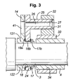
Figure 3 is a cross-sectional side view on the line III-III inFigure 2 ; -
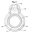
Figure 4 is a cross-sectional end view on the line IV-IV inFigure 5 of a second line cutter of the invention; and -
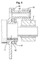
Figure 5 is a cross-sectional side view on the line V-V inFigure 4 . - Referring to the drawings, the line cutter I is fitted at a
propeller 2 on ashaft 3 carried in astem tube 4. - Clamped to the shaft immediately in front of the propeller is a rotatable
cutting blade unit 11 comprising asplit hub 12, having twohalves rotating blade 14 and the other of which carries twofurther blades 15.Bolts 16 clamp the halves to the shaft. Asplit collar 17 is clamped together and to the hub bybolts 17a at a machinedgroove 17b in the hub to provide alocation groove 18 for a stationarycutting blade unit 21. - This assembly has a
single blade 22 integral with ahalf ring 23. Asecond half ring 24 is clipped by interlockingformations location groove 18, with the interposition ofthrust washers - The blades are formed to cross initially at their inner ends on relative rotation and have serrations S formed on them for separating a sizeable line into portions for cutting it. The
thrust washer 18a holds the blades from direct contact. - The arrangement so far described is conventional.
- In accordance with the invention, the
stationary blade 22 has a machined,circular cross-section spigot 25 extending forwards. This is received in acomplementary bore 31 in ablock 32 integral with asplit collar 33 clamped to thestem tube 4 around the shaft journalled in the stem tube. Thebore 31 is parallel with theinternal bore 34 of the collar, whereby thebore 31 andspigot 25 are parallel with the propeller shaft. Thus the stationary blade is located radially and circumferentially. It is further located axially of the shaft by its half ring engaging in thelocation groove 18. - Should the shaft move axially as with thrust direction change from open throttle to closed throttle, the stationary cutter is able to move with the shaft.
- Should a rope become fouled between the stationary blade and one of the rotating blades, the serrations S on the blades part it into bundles of fibres, which are cut between the serrations. The force in this is reacted by the spigot. This removes load from the
half rings - To reduce the drag of the line cutter and in particular that of the stationary blade, the spigot has a through
bore 26, with a tapered inlet. 27. Flow of water through it reduces the tendency for a cavitation bubble to form behind it. Further the rotatingblades drag reduction slots 41. - Referring on to
Figures 4 &5 ,stationary blade 50 thereshown is provided with aclevis 51 in place of the half rings and thesplit location collar 57 is formed of bearing material, whereby a separate thrust bearing is not required at its side of theclevis limbs 52. Further, thereaction block 53 for thestationary blade spigot 55 is attached directly to thestem tube 4. Furthermore, the rotating cutting blade unit is clamped bybolts 56 directly to the hub H of the propeller as opposed to the propeller shaft. - The invention is not intended to be restricted to the details of the above described embodiment. For instance, the
complementary hooks
Claims (14)
- A line cutter for mounting at a propeller itself mounted on a propeller shaft, the line cutter comprising:• a rotatable cutting blade unit mountable fixedly with the propeller shaft for rotation therewith and including:• at least one cutting blade extending generally radially of the propeller shaft and• a pair of opposed thrust surfaces;• a stationary cutting blade unit adapted to be restrained against rotation and having:• a stationary cutting blade and• a pair of opposed thrust surfaces complementary to the thrust surfaces of the rotatable cutting blade unit for locating the stationary cutting blade unit with respect to the rotatable cutting blade unit for line cutting; and characterised by having:• means for restraining the stationary cutting blade against rotation,
wherein:• the restraining means includes a fixable member having a bore at least substantially parallel with the propeller shaft in use and• the stationary cutter has a spigot sized as a sliding fit in the bore for location of the stationary cutter. - A line cutter as claimed in claim 1, wherein the stationary cutting blade unit is located both radially and rotationally with respect to the rotatable cutting blade unit only by the spigot engaging in the bore.
- A line cutter as claimed in claim 1 or claim 2, wherein the spigot is hollow for flow of water therethrough.
- A line cutter as claimed in claim 1, claim 2 or claim 3, wherein the fixable member is an integral part of or be attached to a collar to be clamped onto a stem tube.
- A line cutter as claimed in claim 1, claim 2 or claim 3, wherein the fixable member is an integral feature of a stem tube or of a casing of an outboard motor.
- A line cutter as claimed in claim 1, claim 2 or claim 3, wherein the fixable member is adapted to be attached to a stem tube or of a casing of an outboard motor.
- A line cutter as claimed in any preceding claim, wherein the rotatable cutting blade unit is adapted to be mounted either on the propeller shaft adjacent the propeller or on a complementarily machined part of the propeller.
- A line cutter as claimed in any preceding claim, wherein the stationary cutting blade is formed integrally with an open clevis, the stationary cutting blade extending oppositely from limbs of the clevis and having its thrust surfaces formed on the limbs of the clevis, and restrained in use from radial movement away from the rotatable cutting blade unit by engagement of the spigot in the fixable member, with the limbs of the clevis received between the thrust surfaces of the rotatable cutting blade unit.
- A line cutter as claimed in any one of claims 1 to 7, wherein the stationary cutting blade is formed integrally with a ring which is openable for fitting and closed in use around a hub of the rotating blade assembly, the stationary cutting blade extending away from the ring and having its thrust surfaces formed on the ring, with the ring received between the thrust surfaces of the rotatable cutting blade unit.
- A line cutter as claimed in claim 9, wherein the ring of the stationary cutting blade ring comprises two half rings hooked to each other.
- A line cutter as claimed in claim 9, wherein the ring of the stationary cutting blade ring comprises two half rings bolted to each other.
- A line cutter as claimed in any preceding claim, wherein the rotatable cutting blade unit comprises a thrust ring fitted to a hub of the rotating blade assembly.
- A line cutter as claimed in any preceding claim, including thrust washers between the opposed pairs of thrust surfaces.
- A line cutter as claimed in any preceding claim, wherein the blades include teeth arranged to engage a line at their radially inner ends initially.
Applications Claiming Priority (2)
| Application Number | Priority Date | Filing Date | Title |
|---|---|---|---|
| GBGB0617828.9A GB0617828D0 (en) | 2006-09-11 | 2006-09-11 | Line cutter |
| PCT/GB2007/003458 WO2008032063A1 (en) | 2006-09-11 | 2007-09-11 | Line cutter |
Publications (2)
| Publication Number | Publication Date |
|---|---|
| EP2064112A1 EP2064112A1 (en) | 2009-06-03 |
| EP2064112B1 true EP2064112B1 (en) | 2011-03-09 |
Family
ID=37232709
Family Applications (1)
| Application Number | Title | Priority Date | Filing Date |
|---|---|---|---|
| EP07804252A Not-in-force EP2064112B1 (en) | 2006-09-11 | 2007-09-11 | Line cutter |
Country Status (7)
| Country | Link |
|---|---|
| US (1) | US8062083B2 (en) |
| EP (1) | EP2064112B1 (en) |
| AT (1) | ATE501028T1 (en) |
| DE (1) | DE602007013069D1 (en) |
| DK (1) | DK2064112T3 (en) |
| GB (1) | GB0617828D0 (en) |
| WO (1) | WO2008032063A1 (en) |
Families Citing this family (8)
| Publication number | Priority date | Publication date | Assignee | Title |
|---|---|---|---|---|
| CN107776861B (en) * | 2017-10-18 | 2018-11-30 | 新沂新昆金属制品有限公司 | A kind of ship propeller set |
| KR101865554B1 (en) | 2017-11-13 | 2018-07-04 | 재단법인한국조선해양기자재연구원 | Net and rope cutting apparatus for vessel |
| CN114435571A (en) * | 2020-08-12 | 2022-05-06 | 苏州本特力船用设备有限公司 | Lateral propeller |
| CN112937823B (en) * | 2021-03-10 | 2023-10-13 | 青阳县乔木乡自来水厂 | A spiral drive machine suitable for efficient cleaning of aquatic plants and self-cleaning |
| CN113022815A (en) * | 2021-03-24 | 2021-06-25 | 深圳市夜星寒商贸有限公司 | Underwater rescue equipment capable of preventing water plants from winding |
| CN113734400A (en) * | 2021-10-08 | 2021-12-03 | 大连海事大学 | Propeller anti-winding sleeve type sawtooth cutting tool set and using method thereof |
| KR102553947B1 (en) * | 2021-10-29 | 2023-07-11 | (주)스펄스엠텍 | Appratus for Cutting Net and Rope on Ship |
| CN114956382B (en) * | 2022-05-31 | 2023-04-18 | 浙江飞创环境科技有限公司 | River channel renovation equipment and renovation method thereof |
Family Cites Families (15)
| Publication number | Priority date | Publication date | Assignee | Title |
|---|---|---|---|---|
| US218438A (en) | 1879-08-12 | Improvement in screw-propellers | ||
| FR2507562A1 (en) | 1981-06-15 | 1982-12-17 | Volpini Daniel | Marine vessel drive propeller - has channels through blades to reduce friction of trailing edge |
| NL8105275A (en) | 1981-11-20 | 1983-06-16 | Noordvos Schroeven Bv | SHIP SCREW, PROVIDED WITH TWO OR MORE PERFORATED HOLLOW BLADES. |
| US4447215A (en) | 1982-07-06 | 1984-05-08 | Govan Donald T | Propellor protecting devices |
| US4507091A (en) | 1983-04-04 | 1985-03-26 | Govan Donald T | Propeller protecting devices |
| US4676758A (en) | 1985-09-12 | 1987-06-30 | Dennis Propellers, Inc. | Combined cutter and bypass for propeller |
| GB8531791D0 (en) * | 1985-12-24 | 1986-02-05 | Shaw R D | Line cutting device |
| US4801281A (en) * | 1986-09-12 | 1989-01-31 | Govan Donald T | Line cutter for outboard, inboard/outboard, and trolling motors |
| US4943249A (en) * | 1989-08-11 | 1990-07-24 | Govan Donald T | Line cutter for propellers |
| US4954108A (en) * | 1989-12-04 | 1990-09-04 | Govan Donald T | Line cutter for marine propellers |
| JP2945078B2 (en) | 1990-05-28 | 1999-09-06 | 三信工業株式会社 | Propeller wing structure for ship propulsion |
| US5017167A (en) * | 1990-07-11 | 1991-05-21 | Govan Donald T | Line and weed cutter |
| US5052957A (en) * | 1990-07-11 | 1991-10-01 | Govan Donald T | Support for line and weed cutter |
| US5807150A (en) * | 1997-04-14 | 1998-09-15 | Minter, Sr.; Charles F. | Blade system for marine motors |
| US6004174A (en) * | 1999-02-11 | 1999-12-21 | Govan; Donald T. | Rotary weed and line cutter |
-
2006
- 2006-09-11 GB GBGB0617828.9A patent/GB0617828D0/en not_active Ceased
-
2007
- 2007-09-11 AT AT07804252T patent/ATE501028T1/en not_active IP Right Cessation
- 2007-09-11 WO PCT/GB2007/003458 patent/WO2008032063A1/en not_active Ceased
- 2007-09-11 DE DE602007013069T patent/DE602007013069D1/en active Active
- 2007-09-11 US US12/444,620 patent/US8062083B2/en not_active Expired - Fee Related
- 2007-09-11 DK DK07804252.0T patent/DK2064112T3/en active
- 2007-09-11 EP EP07804252A patent/EP2064112B1/en not_active Not-in-force
Also Published As
| Publication number | Publication date |
|---|---|
| EP2064112A1 (en) | 2009-06-03 |
| US8062083B2 (en) | 2011-11-22 |
| DK2064112T3 (en) | 2011-06-27 |
| US20100075553A1 (en) | 2010-03-25 |
| WO2008032063A1 (en) | 2008-03-20 |
| DE602007013069D1 (en) | 2011-04-21 |
| ATE501028T1 (en) | 2011-03-15 |
| GB0617828D0 (en) | 2006-10-18 |
Similar Documents
| Publication | Publication Date | Title |
|---|---|---|
| EP2064112B1 (en) | Line cutter | |
| EP2311726B1 (en) | Marine propeller with reverse thrust cup | |
| EP2927111B1 (en) | Propeller for ship, and assembling method and disassembling method therefor | |
| KR101979759B1 (en) | Rope cutter for propeller | |
| US4544363A (en) | Line cutter for outboard and inboard/outboard motors | |
| EP0852551A1 (en) | Propulsion and steering unit for a vessel | |
| KR101380650B1 (en) | Propulsion apparatus for ship, and ship having the same | |
| KR200326951Y1 (en) | a propeller lope cutter for a vessel | |
| EP0281565B1 (en) | Line cutting device for mounting around a propeller shaft | |
| KR101205949B1 (en) | Propulsion apparatus for ship and ship including the same | |
| US7008277B2 (en) | Cutting apparatus | |
| KR101949082B1 (en) | Rope cutter for ships | |
| EP0529004B1 (en) | Line and weed cutter and support and method of assembling same | |
| US7837524B2 (en) | Underwater propulsion apparatus performance enhancement device and associated methods | |
| KR101205939B1 (en) | Propulsion apparatus for ship and Ship including the same | |
| CN212951073U (en) | Propeller device with cutting mechanism | |
| KR101045043B1 (en) | Blade bolt fastening device for submerged blade exchange of variable pitch propeller | |
| KR101027951B1 (en) | Simplified tightening of valve rod and double hydraulic pipe of variable pitch propeller | |
| NL2031507B1 (en) | Anti-twisting pump-jet propulsion device and operating method thereof | |
| KR101324963B1 (en) | Propulsion apparatus for ship and ship having the same | |
| WO2004048194A1 (en) | Cutting apparatus for removing debris from a propeller | |
| US9004963B1 (en) | Marine propulsion unit and apparatus for collecting line thereon | |
| KR101444348B1 (en) | Propulsion apparatus for ship, and ship having the same | |
| KR101324967B1 (en) | Propulsion apparatus for ship, and ship having the same | |
| WO2014175746A1 (en) | Quill shaft assembly |
Legal Events
| Date | Code | Title | Description |
|---|---|---|---|
| PUAI | Public reference made under article 153(3) epc to a published international application that has entered the european phase |
Free format text: ORIGINAL CODE: 0009012 |
|
| 17P | Request for examination filed |
Effective date: 20090409 |
|
| AK | Designated contracting states |
Kind code of ref document: A1 Designated state(s): AT BE BG CH CY CZ DE DK EE ES FI FR GB GR HU IE IS IT LI LT LU LV MC MT NL PL PT RO SE SI SK TR |
|
| AX | Request for extension of the european patent |
Extension state: AL BA HR MK RS |
|
| GRAP | Despatch of communication of intention to grant a patent |
Free format text: ORIGINAL CODE: EPIDOSNIGR1 |
|
| GRAC | Information related to communication of intention to grant a patent modified |
Free format text: ORIGINAL CODE: EPIDOSCIGR1 |
|
| GRAS | Grant fee paid |
Free format text: ORIGINAL CODE: EPIDOSNIGR3 |
|
| GRAA | (expected) grant |
Free format text: ORIGINAL CODE: 0009210 |
|
| AK | Designated contracting states |
Kind code of ref document: B1 Designated state(s): AT BE BG CH CY CZ DE DK EE ES FI FR GB GR HU IE IS IT LI LT LU LV MC MT NL PL PT RO SE SI SK TR |
|
| REG | Reference to a national code |
Ref country code: GB Ref legal event code: FG4D |
|
| REG | Reference to a national code |
Ref country code: CH Ref legal event code: EP |
|
| REG | Reference to a national code |
Ref country code: IE Ref legal event code: FG4D |
|
| REF | Corresponds to: |
Ref document number: 602007013069 Country of ref document: DE Date of ref document: 20110421 Kind code of ref document: P |
|
| REG | Reference to a national code |
Ref country code: DE Ref legal event code: R096 Ref document number: 602007013069 Country of ref document: DE Effective date: 20110421 |
|
| REG | Reference to a national code |
Ref country code: DK Ref legal event code: T3 |
|
| REG | Reference to a national code |
Ref country code: SE Ref legal event code: TRGR |
|
| REG | Reference to a national code |
Ref country code: NL Ref legal event code: T3 |
|
| PG25 | Lapsed in a contracting state [announced via postgrant information from national office to epo] |
Ref country code: GR Free format text: LAPSE BECAUSE OF FAILURE TO SUBMIT A TRANSLATION OF THE DESCRIPTION OR TO PAY THE FEE WITHIN THE PRESCRIBED TIME-LIMIT Effective date: 20110610 Ref country code: ES Free format text: LAPSE BECAUSE OF FAILURE TO SUBMIT A TRANSLATION OF THE DESCRIPTION OR TO PAY THE FEE WITHIN THE PRESCRIBED TIME-LIMIT Effective date: 20110620 Ref country code: LV Free format text: LAPSE BECAUSE OF FAILURE TO SUBMIT A TRANSLATION OF THE DESCRIPTION OR TO PAY THE FEE WITHIN THE PRESCRIBED TIME-LIMIT Effective date: 20110309 Ref country code: LT Free format text: LAPSE BECAUSE OF FAILURE TO SUBMIT A TRANSLATION OF THE DESCRIPTION OR TO PAY THE FEE WITHIN THE PRESCRIBED TIME-LIMIT Effective date: 20110309 |
|
| LTIE | Lt: invalidation of european patent or patent extension |
Effective date: 20110309 |
|
| PG25 | Lapsed in a contracting state [announced via postgrant information from national office to epo] |
Ref country code: AT Free format text: LAPSE BECAUSE OF FAILURE TO SUBMIT A TRANSLATION OF THE DESCRIPTION OR TO PAY THE FEE WITHIN THE PRESCRIBED TIME-LIMIT Effective date: 20110309 Ref country code: CY Free format text: LAPSE BECAUSE OF FAILURE TO SUBMIT A TRANSLATION OF THE DESCRIPTION OR TO PAY THE FEE WITHIN THE PRESCRIBED TIME-LIMIT Effective date: 20110309 Ref country code: BG Free format text: LAPSE BECAUSE OF FAILURE TO SUBMIT A TRANSLATION OF THE DESCRIPTION OR TO PAY THE FEE WITHIN THE PRESCRIBED TIME-LIMIT Effective date: 20110609 Ref country code: FI Free format text: LAPSE BECAUSE OF FAILURE TO SUBMIT A TRANSLATION OF THE DESCRIPTION OR TO PAY THE FEE WITHIN THE PRESCRIBED TIME-LIMIT Effective date: 20110309 Ref country code: SI Free format text: LAPSE BECAUSE OF FAILURE TO SUBMIT A TRANSLATION OF THE DESCRIPTION OR TO PAY THE FEE WITHIN THE PRESCRIBED TIME-LIMIT Effective date: 20110309 |
|
| PG25 | Lapsed in a contracting state [announced via postgrant information from national office to epo] |
Ref country code: BE Free format text: LAPSE BECAUSE OF FAILURE TO SUBMIT A TRANSLATION OF THE DESCRIPTION OR TO PAY THE FEE WITHIN THE PRESCRIBED TIME-LIMIT Effective date: 20110309 |
|
| PG25 | Lapsed in a contracting state [announced via postgrant information from national office to epo] |
Ref country code: EE Free format text: LAPSE BECAUSE OF FAILURE TO SUBMIT A TRANSLATION OF THE DESCRIPTION OR TO PAY THE FEE WITHIN THE PRESCRIBED TIME-LIMIT Effective date: 20110309 Ref country code: PT Free format text: LAPSE BECAUSE OF FAILURE TO SUBMIT A TRANSLATION OF THE DESCRIPTION OR TO PAY THE FEE WITHIN THE PRESCRIBED TIME-LIMIT Effective date: 20110711 |
|
| PG25 | Lapsed in a contracting state [announced via postgrant information from national office to epo] |
Ref country code: SK Free format text: LAPSE BECAUSE OF FAILURE TO SUBMIT A TRANSLATION OF THE DESCRIPTION OR TO PAY THE FEE WITHIN THE PRESCRIBED TIME-LIMIT Effective date: 20110309 Ref country code: RO Free format text: LAPSE BECAUSE OF FAILURE TO SUBMIT A TRANSLATION OF THE DESCRIPTION OR TO PAY THE FEE WITHIN THE PRESCRIBED TIME-LIMIT Effective date: 20110309 Ref country code: CZ Free format text: LAPSE BECAUSE OF FAILURE TO SUBMIT A TRANSLATION OF THE DESCRIPTION OR TO PAY THE FEE WITHIN THE PRESCRIBED TIME-LIMIT Effective date: 20110309 Ref country code: IS Free format text: LAPSE BECAUSE OF FAILURE TO SUBMIT A TRANSLATION OF THE DESCRIPTION OR TO PAY THE FEE WITHIN THE PRESCRIBED TIME-LIMIT Effective date: 20110709 |
|
| PLBE | No opposition filed within time limit |
Free format text: ORIGINAL CODE: 0009261 |
|
| STAA | Information on the status of an ep patent application or granted ep patent |
Free format text: STATUS: NO OPPOSITION FILED WITHIN TIME LIMIT |
|
| 26N | No opposition filed |
Effective date: 20111212 |
|
| PG25 | Lapsed in a contracting state [announced via postgrant information from national office to epo] |
Ref country code: PL Free format text: LAPSE BECAUSE OF FAILURE TO SUBMIT A TRANSLATION OF THE DESCRIPTION OR TO PAY THE FEE WITHIN THE PRESCRIBED TIME-LIMIT Effective date: 20110309 |
|
| REG | Reference to a national code |
Ref country code: DE Ref legal event code: R097 Ref document number: 602007013069 Country of ref document: DE Effective date: 20111212 |
|
| PG25 | Lapsed in a contracting state [announced via postgrant information from national office to epo] |
Ref country code: MC Free format text: LAPSE BECAUSE OF NON-PAYMENT OF DUE FEES Effective date: 20110930 |
|
| REG | Reference to a national code |
Ref country code: CH Ref legal event code: PL |
|
| PG25 | Lapsed in a contracting state [announced via postgrant information from national office to epo] |
Ref country code: IT Free format text: LAPSE BECAUSE OF FAILURE TO SUBMIT A TRANSLATION OF THE DESCRIPTION OR TO PAY THE FEE WITHIN THE PRESCRIBED TIME-LIMIT Effective date: 20110309 |
|
| REG | Reference to a national code |
Ref country code: IE Ref legal event code: MM4A |
|
| PG25 | Lapsed in a contracting state [announced via postgrant information from national office to epo] |
Ref country code: LI Free format text: LAPSE BECAUSE OF NON-PAYMENT OF DUE FEES Effective date: 20110930 Ref country code: CH Free format text: LAPSE BECAUSE OF NON-PAYMENT OF DUE FEES Effective date: 20110930 Ref country code: IE Free format text: LAPSE BECAUSE OF NON-PAYMENT OF DUE FEES Effective date: 20110911 |
|
| PG25 | Lapsed in a contracting state [announced via postgrant information from national office to epo] |
Ref country code: MT Free format text: LAPSE BECAUSE OF FAILURE TO SUBMIT A TRANSLATION OF THE DESCRIPTION OR TO PAY THE FEE WITHIN THE PRESCRIBED TIME-LIMIT Effective date: 20110309 |
|
| PG25 | Lapsed in a contracting state [announced via postgrant information from national office to epo] |
Ref country code: LU Free format text: LAPSE BECAUSE OF NON-PAYMENT OF DUE FEES Effective date: 20110911 |
|
| PG25 | Lapsed in a contracting state [announced via postgrant information from national office to epo] |
Ref country code: TR Free format text: LAPSE BECAUSE OF FAILURE TO SUBMIT A TRANSLATION OF THE DESCRIPTION OR TO PAY THE FEE WITHIN THE PRESCRIBED TIME-LIMIT Effective date: 20110309 |
|
| PG25 | Lapsed in a contracting state [announced via postgrant information from national office to epo] |
Ref country code: HU Free format text: LAPSE BECAUSE OF FAILURE TO SUBMIT A TRANSLATION OF THE DESCRIPTION OR TO PAY THE FEE WITHIN THE PRESCRIBED TIME-LIMIT Effective date: 20110309 |
|
| REG | Reference to a national code |
Ref country code: FR Ref legal event code: ST Effective date: 20150529 |
|
| PG25 | Lapsed in a contracting state [announced via postgrant information from national office to epo] |
Ref country code: FR Free format text: LAPSE BECAUSE OF NON-PAYMENT OF DUE FEES Effective date: 20140930 |
|
| REG | Reference to a national code |
Ref country code: FR Ref legal event code: PLFP Year of fee payment: 9 |
|
| REG | Reference to a national code |
Ref country code: FR Ref legal event code: RN Effective date: 20150709 |
|
| REG | Reference to a national code |
Ref country code: FR Ref legal event code: FC Effective date: 20151026 |
|
| PGRI | Patent reinstated in contracting state [announced from national office to epo] |
Ref country code: FR Effective date: 20151218 |
|
| REG | Reference to a national code |
Ref country code: FR Ref legal event code: PLFP Year of fee payment: 10 |
|
| PGFP | Annual fee paid to national office [announced via postgrant information from national office to epo] |
Ref country code: FR Payment date: 20170329 Year of fee payment: 10 Ref country code: NL Payment date: 20170329 Year of fee payment: 10 Ref country code: SE Payment date: 20170329 Year of fee payment: 10 |
|
| PGFP | Annual fee paid to national office [announced via postgrant information from national office to epo] |
Ref country code: DK Payment date: 20170330 Year of fee payment: 10 Ref country code: GB Payment date: 20170329 Year of fee payment: 10 |
|
| PGFP | Annual fee paid to national office [announced via postgrant information from national office to epo] |
Ref country code: DE Payment date: 20170329 Year of fee payment: 10 |
|
| REG | Reference to a national code |
Ref country code: DE Ref legal event code: R119 Ref document number: 602007013069 Country of ref document: DE |
|
| REG | Reference to a national code |
Ref country code: DK Ref legal event code: EBP Effective date: 20170930 |
|
| REG | Reference to a national code |
Ref country code: SE Ref legal event code: EUG |
|
| REG | Reference to a national code |
Ref country code: NL Ref legal event code: MM Effective date: 20171001 |
|
| GBPC | Gb: european patent ceased through non-payment of renewal fee |
Effective date: 20170911 |
|
| PG25 | Lapsed in a contracting state [announced via postgrant information from national office to epo] |
Ref country code: NL Free format text: LAPSE BECAUSE OF NON-PAYMENT OF DUE FEES Effective date: 20171001 |
|
| REG | Reference to a national code |
Ref country code: FR Ref legal event code: ST Effective date: 20180531 |
|
| PG25 | Lapsed in a contracting state [announced via postgrant information from national office to epo] |
Ref country code: DE Free format text: LAPSE BECAUSE OF NON-PAYMENT OF DUE FEES Effective date: 20180404 Ref country code: GB Free format text: LAPSE BECAUSE OF NON-PAYMENT OF DUE FEES Effective date: 20170911 |
|
| PG25 | Lapsed in a contracting state [announced via postgrant information from national office to epo] |
Ref country code: FR Free format text: LAPSE BECAUSE OF NON-PAYMENT OF DUE FEES Effective date: 20171002 |
|
| PG25 | Lapsed in a contracting state [announced via postgrant information from national office to epo] |
Ref country code: DK Free format text: LAPSE BECAUSE OF NON-PAYMENT OF DUE FEES Effective date: 20170930 |
|
| PG25 | Lapsed in a contracting state [announced via postgrant information from national office to epo] |
Ref country code: SE Free format text: LAPSE BECAUSE OF NON-PAYMENT OF DUE FEES Effective date: 20170912 |