EP2064123B1 - Karton mit verstärkten grifföffnungen - Google Patents
Karton mit verstärkten grifföffnungen Download PDFInfo
- Publication number
- EP2064123B1 EP2064123B1 EP07814535A EP07814535A EP2064123B1 EP 2064123 B1 EP2064123 B1 EP 2064123B1 EP 07814535 A EP07814535 A EP 07814535A EP 07814535 A EP07814535 A EP 07814535A EP 2064123 B1 EP2064123 B1 EP 2064123B1
- Authority
- EP
- European Patent Office
- Prior art keywords
- edge
- flap
- reinforcing
- handle opening
- carton
- Prior art date
- Legal status (The legal status is an assumption and is not a legal conclusion. Google has not performed a legal analysis and makes no representation as to the accuracy of the status listed.)
- Not-in-force
Links
- 230000003014 reinforcing effect Effects 0.000 claims abstract description 213
- 230000002787 reinforcement Effects 0.000 claims description 17
- 230000000295 complement effect Effects 0.000 claims description 9
- 239000000463 material Substances 0.000 description 19
- 238000000034 method Methods 0.000 description 11
- 239000000853 adhesive Substances 0.000 description 10
- 230000001070 adhesive effect Effects 0.000 description 10
- 239000010410 layer Substances 0.000 description 6
- 238000004519 manufacturing process Methods 0.000 description 5
- 238000013459 approach Methods 0.000 description 3
- 238000004806 packaging method and process Methods 0.000 description 3
- 239000002356 single layer Substances 0.000 description 3
- 238000013461 design Methods 0.000 description 2
- 239000011087 paperboard Substances 0.000 description 2
- 238000004026 adhesive bonding Methods 0.000 description 1
- 230000009286 beneficial effect Effects 0.000 description 1
- 235000013361 beverage Nutrition 0.000 description 1
- 230000015572 biosynthetic process Effects 0.000 description 1
- -1 corrugated board Substances 0.000 description 1
- 238000012986 modification Methods 0.000 description 1
- 230000004048 modification Effects 0.000 description 1
- 238000012856 packing Methods 0.000 description 1
- 238000006467 substitution reaction Methods 0.000 description 1
Images


Classifications
-
- B—PERFORMING OPERATIONS; TRANSPORTING
- B65—CONVEYING; PACKING; STORING; HANDLING THIN OR FILAMENTARY MATERIAL
- B65D—CONTAINERS FOR STORAGE OR TRANSPORT OF ARTICLES OR MATERIALS, e.g. BAGS, BARRELS, BOTTLES, BOXES, CANS, CARTONS, CRATES, DRUMS, JARS, TANKS, HOPPERS, FORWARDING CONTAINERS; ACCESSORIES, CLOSURES, OR FITTINGS THEREFOR; PACKAGING ELEMENTS; PACKAGES
- B65D5/00—Rigid or semi-rigid containers of polygonal cross-section, e.g. boxes, cartons or trays, formed by folding or erecting one or more blanks made of paper
- B65D5/42—Details of containers or of foldable or erectable container blanks
- B65D5/44—Integral, inserted or attached portions forming internal or external fittings
- B65D5/46—Handles
- B65D5/46072—Handles integral with the container
- B65D5/4608—Handgrip holes
-
- B—PERFORMING OPERATIONS; TRANSPORTING
- B65—CONVEYING; PACKING; STORING; HANDLING THIN OR FILAMENTARY MATERIAL
- B65D—CONTAINERS FOR STORAGE OR TRANSPORT OF ARTICLES OR MATERIALS, e.g. BAGS, BARRELS, BOTTLES, BOXES, CANS, CARTONS, CRATES, DRUMS, JARS, TANKS, HOPPERS, FORWARDING CONTAINERS; ACCESSORIES, CLOSURES, OR FITTINGS THEREFOR; PACKAGING ELEMENTS; PACKAGES
- B65D5/00—Rigid or semi-rigid containers of polygonal cross-section, e.g. boxes, cartons or trays, formed by folding or erecting one or more blanks made of paper
- B65D5/02—Rigid or semi-rigid containers of polygonal cross-section, e.g. boxes, cartons or trays, formed by folding or erecting one or more blanks made of paper by folding or erecting a single blank to form a tubular body with or without subsequent folding operations, or the addition of separate elements, to close the ends of the body
- B65D5/0227—Rigid or semi-rigid containers of polygonal cross-section, e.g. boxes, cartons or trays, formed by folding or erecting one or more blanks made of paper by folding or erecting a single blank to form a tubular body with or without subsequent folding operations, or the addition of separate elements, to close the ends of the body with end closures formed by inward folding of flaps and securing them by heat-sealing, by applying adhesive to the flaps or by staples
-
- B—PERFORMING OPERATIONS; TRANSPORTING
- B65—CONVEYING; PACKING; STORING; HANDLING THIN OR FILAMENTARY MATERIAL
- B65D—CONTAINERS FOR STORAGE OR TRANSPORT OF ARTICLES OR MATERIALS, e.g. BAGS, BARRELS, BOTTLES, BOXES, CANS, CARTONS, CRATES, DRUMS, JARS, TANKS, HOPPERS, FORWARDING CONTAINERS; ACCESSORIES, CLOSURES, OR FITTINGS THEREFOR; PACKAGING ELEMENTS; PACKAGES
- B65D71/00—Bundles of articles held together by packaging elements for convenience of storage or transport, e.g. portable segregating carrier for plural receptacles such as beer cans or pop bottles; Bales of material
- B65D71/06—Packaging elements holding or encircling completely or almost completely the bundle of articles, e.g. wrappers
- B65D71/12—Packaging elements holding or encircling completely or almost completely the bundle of articles, e.g. wrappers the packaging elements, e.g. wrappers being formed by folding a single blank
- B65D71/36—Packaging elements holding or encircling completely or almost completely the bundle of articles, e.g. wrappers the packaging elements, e.g. wrappers being formed by folding a single blank having a tubular shape, e.g. tubular wrappers, with end walls
-
- B—PERFORMING OPERATIONS; TRANSPORTING
- B65—CONVEYING; PACKING; STORING; HANDLING THIN OR FILAMENTARY MATERIAL
- B65D—CONTAINERS FOR STORAGE OR TRANSPORT OF ARTICLES OR MATERIALS, e.g. BAGS, BARRELS, BOTTLES, BOXES, CANS, CARTONS, CRATES, DRUMS, JARS, TANKS, HOPPERS, FORWARDING CONTAINERS; ACCESSORIES, CLOSURES, OR FITTINGS THEREFOR; PACKAGING ELEMENTS; PACKAGES
- B65D2571/00—Bundles of articles held together by packaging elements for convenience of storage or transport, e.g. portable segregating carrier for plural receptacles such as beer cans, pop bottles; Bales of material
- B65D2571/00123—Bundling wrappers or trays
- B65D2571/00129—Wrapper locking means
- B65D2571/00135—Wrapper locking means integral with the wrapper
- B65D2571/00141—Wrapper locking means integral with the wrapper glued
-
- B—PERFORMING OPERATIONS; TRANSPORTING
- B65—CONVEYING; PACKING; STORING; HANDLING THIN OR FILAMENTARY MATERIAL
- B65D—CONTAINERS FOR STORAGE OR TRANSPORT OF ARTICLES OR MATERIALS, e.g. BAGS, BARRELS, BOTTLES, BOXES, CANS, CARTONS, CRATES, DRUMS, JARS, TANKS, HOPPERS, FORWARDING CONTAINERS; ACCESSORIES, CLOSURES, OR FITTINGS THEREFOR; PACKAGING ELEMENTS; PACKAGES
- B65D2571/00—Bundles of articles held together by packaging elements for convenience of storage or transport, e.g. portable segregating carrier for plural receptacles such as beer cans, pop bottles; Bales of material
- B65D2571/00123—Bundling wrappers or trays
- B65D2571/00432—Handles or suspending means
- B65D2571/00438—Holes
- B65D2571/0045—Holes for hands
-
- B—PERFORMING OPERATIONS; TRANSPORTING
- B65—CONVEYING; PACKING; STORING; HANDLING THIN OR FILAMENTARY MATERIAL
- B65D—CONTAINERS FOR STORAGE OR TRANSPORT OF ARTICLES OR MATERIALS, e.g. BAGS, BARRELS, BOTTLES, BOXES, CANS, CARTONS, CRATES, DRUMS, JARS, TANKS, HOPPERS, FORWARDING CONTAINERS; ACCESSORIES, CLOSURES, OR FITTINGS THEREFOR; PACKAGING ELEMENTS; PACKAGES
- B65D2571/00—Bundles of articles held together by packaging elements for convenience of storage or transport, e.g. portable segregating carrier for plural receptacles such as beer cans, pop bottles; Bales of material
- B65D2571/00123—Bundling wrappers or trays
- B65D2571/00432—Handles or suspending means
- B65D2571/00518—Handles or suspending means with reinforcements
- B65D2571/00524—Handles or suspending means with reinforcements integral
-
- B—PERFORMING OPERATIONS; TRANSPORTING
- B65—CONVEYING; PACKING; STORING; HANDLING THIN OR FILAMENTARY MATERIAL
- B65D—CONTAINERS FOR STORAGE OR TRANSPORT OF ARTICLES OR MATERIALS, e.g. BAGS, BARRELS, BOTTLES, BOXES, CANS, CARTONS, CRATES, DRUMS, JARS, TANKS, HOPPERS, FORWARDING CONTAINERS; ACCESSORIES, CLOSURES, OR FITTINGS THEREFOR; PACKAGING ELEMENTS; PACKAGES
- B65D2571/00—Bundles of articles held together by packaging elements for convenience of storage or transport, e.g. portable segregating carrier for plural receptacles such as beer cans, pop bottles; Bales of material
- B65D2571/00123—Bundling wrappers or trays
- B65D2571/00555—Wrapper opening devices
- B65D2571/00561—Lines of weakness
- B65D2571/00574—Lines of weakness whereby contents can still be carried after the line has been torn
-
- B—PERFORMING OPERATIONS; TRANSPORTING
- B65—CONVEYING; PACKING; STORING; HANDLING THIN OR FILAMENTARY MATERIAL
- B65D—CONTAINERS FOR STORAGE OR TRANSPORT OF ARTICLES OR MATERIALS, e.g. BAGS, BARRELS, BOTTLES, BOXES, CANS, CARTONS, CRATES, DRUMS, JARS, TANKS, HOPPERS, FORWARDING CONTAINERS; ACCESSORIES, CLOSURES, OR FITTINGS THEREFOR; PACKAGING ELEMENTS; PACKAGES
- B65D2571/00—Bundles of articles held together by packaging elements for convenience of storage or transport, e.g. portable segregating carrier for plural receptacles such as beer cans, pop bottles; Bales of material
- B65D2571/00123—Bundling wrappers or trays
- B65D2571/00648—Elements used to form the wrapper
- B65D2571/00654—Blanks
- B65D2571/0066—Blanks formed from one single sheet
-
- B—PERFORMING OPERATIONS; TRANSPORTING
- B65—CONVEYING; PACKING; STORING; HANDLING THIN OR FILAMENTARY MATERIAL
- B65D—CONTAINERS FOR STORAGE OR TRANSPORT OF ARTICLES OR MATERIALS, e.g. BAGS, BARRELS, BOTTLES, BOXES, CANS, CARTONS, CRATES, DRUMS, JARS, TANKS, HOPPERS, FORWARDING CONTAINERS; ACCESSORIES, CLOSURES, OR FITTINGS THEREFOR; PACKAGING ELEMENTS; PACKAGES
- B65D2571/00—Bundles of articles held together by packaging elements for convenience of storage or transport, e.g. portable segregating carrier for plural receptacles such as beer cans, pop bottles; Bales of material
- B65D2571/00123—Bundling wrappers or trays
- B65D2571/00709—Shape of the formed wrapper, i.e. shape of each formed element if the wrapper is made from more than one element
- B65D2571/00722—Shape of the formed wrapper, i.e. shape of each formed element if the wrapper is made from more than one element tubular with end walls, e.g. walls not extending on the whole end surface
- B65D2571/00728—Shape of the formed wrapper, i.e. shape of each formed element if the wrapper is made from more than one element tubular with end walls, e.g. walls not extending on the whole end surface the end walls being closed by gluing
Definitions
- This invention relates generally to cartons, and particularly to a carton having a reinforced handle opening.
- Carton manufacturers often face the challenge of providing a carton with handles that are sufficiently strong to support the weight of a group of articles while minimizing material costs.
- the desired thickness of the material that is used to form the carton has a burst strength that is insufficient to avoid failure of the handle under the stress caused by the weight of the articles.
- a handle opening in a carton end wall may be reinforced by outlining its edges with an additional layer of sheet material.
- Cartons are sometimes formed from a blank that includes side end flaps and top end flaps that at least partially define an end closure.
- the top end flap includes a handle opening and the side end flaps include cutouts such that the side end flaps reinforce the handle opening, as known in the art.
- side flap reinforcing panels which are hingedly connected to the side end flaps.
- the side flap reinforcing panels are foldable to overlap at least a portion of the side end flaps adjacent to the cutouts.
- such a blank requires special folding and gluing steps and is thereby more difficult and costly to manufacture.
- What is needed is a carton that is formed from a single blank, provides a reinforced handle opening, is efficiently constructed without wasting expensive material to reinforce portions of the carton that are less likely to fail, and is easily erected.
- a carton according to the preamble of claim 1 and a blank according to the preamble of claim 7 are disclosed in US-A-3,933,300 .
- the first aspect of the present invention provides a carton comprising a tubular structure comprising multiple walls including a top wall, bottom wall, and first and second side walls, an edge flap connecting two of said walls and at least one end closure that comprises a top end flap hingedly connected to said top wall and which top end flap comprises a handle opening; a bottom end flap hingedly connected to said bottom wall and; a first edge flap reinforcing panel that is hingedly connected to said edge flap; wherein a reinforcing edge of said first edge flap reinforcing panel is disposed in reinforcing proximity to said handle opening so as to reinforce at least a weight bearing edge of said handle opening, and wherein said at least one end closure further comprises a second edge flap reinforcing panel that is hingedly connected to said first edge flap reinforcing panel, wherein a reinforcing edge of said second edge flap reinforcing panel disposed in reinforcing proximity to said handle opening so as to reinforce at least said weight bearing edge of said handle opening.
- said at least one end closure further comprises a side end flap hingedly connected to each of the first and second side walls, each side end flap comprising a cutout, wherein end edges of said side end flaps are adjacent to one another such that said cutouts are aligned to define the handle opening of said at least one end closure structure.
- said at least one end closure further comprises a side end flap hingedly connected to each of the first and second side walls, each side end flap comprising a cutout having dimensions complementary to the dimensions of at least part of said handle opening, and wherein said top end flap is foldable to at least partially overlie said side end flaps so that said handle opening in said top end flap is in registry with said cutouts in said first and second side end flaps.
- At least one of said side end flaps comprises a side flap reinforcing panel having a reinforcing edge, said side flap reinforcing panel being foldable to place said reinforcing edge in reinforcing proximity to said cutout of said at least one said side end flap.
- first and second edge flap reinforcing panels cooperate with said side flap reinforcing panel to provide multiple layers of reinforcement to at least said weight bearing edge of said handle opening.
- said handle opening is defined by an endless edge.
- a second aspect of the present invention provides a blank for forming a carton, comprising a plurality of hingedly connected primary panels for forming the walls including a top wall, bottom wall and first and second side walls of a tubular structure; an edge flap hingedly connected to one of the endmost of said primary panels, said edge flap for connecting the endmost primary panels to form said tubular structure; and a plurality of end flaps for forming an end closure at one end of said carton including a top end flap hinged to said top wall and a bottom end flap hinged to said bottom edge, each of said plurality of end flaps being hingedly connected to the corresponding end edge of one of said primary panels, said end flaps for forming an end closure, wherein at least one of said plurality of end flaps includes a feature for defining a handle opening disposed through said end closure, a first edge flap reinforcing panel being hingedly connected to said edge flap, wherein a reinforcing edge of said first edge flap reinforcing panel is positioned and dimensioned for
- top end flaps include an endless edged aperture for defining said handle opening.
- At least two of said plurality of end flaps includes a complementary cutout for defining said handle opening.
- the various embodiments of the present invention overcome the shortcomings of the prior art by providing a carton formed from a single sheet of paperboard or other foldable sheet material.
- the carton includes a handle disposed in an end closure, wherein at least a part of the weight bearing portion of the periphery of the handle opening which defines the handle is reinforced by at least two reinforcing panels. At least the first reinforcing panel is advantageously, connected to an edge flap which holds the carton together. A second reinforcing panel is hingedly connected to the first reinforcing panel.
- edge flap reinforcing panels provides multiple layers of reinforcement to any of numerous handle structure designs.
- the exemplary embodlments are described in the context of a carton that includes a top wall, a bottom wall, and first and second side walls, each connected to the next to form a tubular structure. Two of the walls of the tubular structure are secured together along an edge flap. More specifically, the edge flap is hingedly connected to one of the walls of the carton and adhesive is applied to the edge flap to secure the edge flap to another of the walls of the carton. Thereby, these walls of the carton are hingedly connected to one another by way of the edge flap.
- An end closure is formed from end flaps at each open end of the tubular structure to define the end walls of the carton.
- the top end flap includes a handle opening and the side end flaps include cutouts which together at least partially define the handle in the end closure structure.
- the end closure includes at least a first edge flap reinforcing panel that is hingedly connected to the edge flap.
- a second edge flap reinforcing panel is hingedly connected to the first edge flap reinforcing panel.
- Each edge flap reinforcing panel includes a reinforcing edge that is disposed in reinforcing proximity to the handle opening of the end closure structure.
- Each reinforcing edge reinforces at least a portion of the weight bearing edge of the handle opening that defines the handle.
- the reinforcing edges of the edge flap reinforcing panels have contours and dimensions that are complementary to the dimensions of the handle opening.
- the reinforcing edge of each of the edge flap reinforcing panels is a lower edge. It is contemplated that, in other embodiments, one or both of the edge flap reinforcing panels can include a cutout or an aperture that defines a reinforcing edge.
- the tubular structure is formed from a top wall, a bottom wall, and first and second side walls.
- the end closures which are formed at each open end of the tubular structure are formed from end flaps which are hingedly connected to each of the walls of the tubular structure.
- the end closure includes a top end flap that is hingedly connected to the top panel which includes a handle opening disposed therethrough.
- the end closure also includes side end flaps that are hingedly connected to the first and second side walls respectively.
- each side end flap includes a cutout that is disposed or formed at a distal end edge of each side end flap. In either case, the cutout has dimensions that are complementary to the dimensions or at least part of the handle opening.
- One or both side end flaps can optionally include a side flap reinforcing panel having a reinforcing edge, the side flap reinforcing panel being foldable to place its reinforcing edge in reinforcing proximity to the respective cutout.
- the end closure and handle are formed as the top end flap is folded to at least partially overlie the first and second side end flaps so that the handle opening in the top end flap is in registry with the cutouts in the first and second side end flaps.
- the edge flap reinforcing panel can be secured to one or both of the side end flaps such that, as the end closure is formed, the edge flap reinforcing panel is disposed in reinforcing proximity to the handle opening so as to reinforce at least the weight bearing edge of the handle opening or to otherwise further form the handle.
- the end closure handle is formed from the handle opening In the top end flap and by the first and second edge flap reinforcing panels.
- the handle is not formed by side end flap cutouts, which are in registry with the handle opening in other embodiments.
- the handle opening can be defined or approximated by cutouts in multiple end flaps such as the side end flaps.
- the end closure handle can be formed from a handle opening in the top end flap, cutouts in the side end flaps, the first and second edge flap reinforcing panels, and at least one side flap reinforcing panel that is hingedly connected one of the side end flaps.
- the weight bearing edge of the handle is at least four plies thick.
- FIGs.1 through 9 illustrate embodiments not forming part of the invention. It must be understood that the disclosed embodiments are merely exemplary of the invention that may be embodied in various and alternative forms, and combinations thereof.
- the word "exemplary” is used expansively to refer to embodiments that serve as illustrations, specimens, models, or patterns. The figures are not necessarily to scale and some features may be exaggerated or minimized to show details of particular components. In other instances, well-known components, systems, materials, or methods have not been described in detail in order to avoid obscuring the present invention. Therefore, specific structural and functional details disclosed herein are not to be interpreted as limiting, but merely as a basis for the claims and as a representative basis for teaching one skilled in the art to variously employ the present invention.
- the carton includes a handle opening disposed in an end closure, wherein at least a part of the weight bearing portion of the periphery of the handle opening is reinforced by at least two edge flap reinforcing panels. At least the first edge flap reinforcing panel is hingedly connected to an edge flap that facilitates connecting the walls of a tubular structure. The second edge flap reinforcing panel is hingedly connected to the first edge flap reinforcing panel.
- the exemplary embodiments of the carton of the present invention are for enclosing, carrying, and dispensing articles such as beverage cans or bottles, although the teachings of the present invention may be incorporated in cartons or other containers that are utilized to package any suitable article.
- the exemplary cartons are formed from a foldable sheet material such as paperboard, corrugated board, plastic, or the like.
- a blank 100 is cut from a single sheet of foldable sheet material, although it is contemplated that the blank 100 may include several separate panels that are secured together.
- the inside surface the blank 100 is shown.
- the blank 100 includes primary panels that form the walls of a tubular structure, as described in further detail below.
- the primary panels are aligned along a longitudinal axis of the blank 100 and hingedly connected one to the next along transverse fold lines, which are substantially perpendicular to the longitudinal axis of the blank 100.
- the primary panels include a top panel 102, a first side panel 104, a bottom panel 106, and a second side panel 108.
- the top panel 102 is hingedly connected to the first side panel 104 along fold line 110, the first side panel 104 is hingedly connected to the bottom panel 106 along fold line 112, and the bottom panel 106 is hingedly connected to the second side panel 108 along fold line 114.
- the blank 100 includes an edge flap 116 that facilitates connecting the primary panels to form a tubular structure.
- the edge flap 116 is hingedly connected to the top panel 102 along fold line 118.
- the blank 100 further includes end flaps that are hingedly connected to opposite end edges of each of the primary panels 102, 104, 106, 108.
- the end flaps are folded and secured to form end closures at each end of the erected carton 200, as described in further detail below.
- Top end flaps 120a, 120b are hingedly connected to top panel 102 along fold lines 122a, 122b.
- First side end flaps 124a, 124b are hingedly connected to first side panel 104 along fold lines 126a, 126b.
- Bottom end flaps 128a, 128b are hingedly connected to bottom panel 106 along fold lines 130a, 130b.
- Second side end flaps 132a, 132b are hingedly connected to second side end panel 108 along fold lines 134a, 134b.
- edge flap reinforcing panels 160a, 160b are hingedly connected to the edge flap 116 along fold lines 162a, 162b.
- the edge flap reinforcing panels 160a, 160b each have a reinforcing edge E1.
- the blank 100 can optionally include an opening feature F to allow access to articles within the carton 200.
- the top panel 102 includes a pattern of severance lines S that define the opening feature F.
- the opening feature F is not limited to the opening features F illustrated and described herein. Rather, the opening feature F is a design decision that is at least partially determined by the articles enclosed in the carton and how much access to those articles is desired.
- the opening feature F can be disposed in any one or more of the panels and can be defined by any pattern of severance lines. Further, the opening feature can include tear strips, zippers, cut lines, apertures, slits, and the like.
- the exemplary cartons can be partially enclosed such that a permanent opening is included in one or more walls.
- frrangible line or "severance line” includes, but is not limited to, perforations, a line of perforations, a line of short slits, a line of half cuts, a single half cut, any combination of perforations, slits, and half cuts, short score lines, combinations thereof and the like.
- top end flaps 120a, 120b include handle openings 136a, 136b; first side end flaps 124a, 124b include cutouts 144a, 144b; and second side end flaps 132a, 132b include cutouts 152a, 152b, respectively.
- the cutouts 144a, 152a are dimensioned and positioned such that they are complementary to a respective handle opening 136a, as described in further detail below.
- Each of the handle openings 136a, 136b is an aperture defined by an endless edge 138a, 138b, respectively, that defines an ergonomic shape suitable for receiving the fingers of a user's hand so that the carton 200 can be easily lifted and carried.
- the exemplary handle openings are formed from a single panel, the endless edge thereof may instead be approximated by portions of two or more adjacent panels.
- cushioning flaps 140a, 140b are hingedly connected along a portion of the respective edge 138a, 138b of the handle openings 136a, 136b.
- the portions of the edges 138a, 138b along which the cushioning flaps 140a, 140b are hingedly connected is defined by fold lines 142a, 142b that enable the cushioning flaps 140a, 140b to fold inward to provide a cushioned edge for a user to engage.
- the cutouts 144a, 152a are defined by edges 150a, 154a such that the handle opening 136a and the cutouts 144a, 152a have complementary shapes, dimensions, and positions so as to be placed in registry with one another when the end flaps 120a, 124a, 132a are folded to overlie, overlap, or abut one another and thereby form a first end closure, as described in further detail below.
- handle opening 136b and cutouts 144b, 152b are complementarily shaped, dimensioned, and positioned so as to be placed in registry with one another when end flaps 120b, 124b, 132b are folded to overlie, overlap, or abut one another and thereby form a second end closure, as described in further detail below.
- side flap reinforcing panels 164a, 164b are hingedly connected to side end flaps 124a, 124b along fold lines 166a, 166b, respectively, such that the side flap reinforcing panels 164a, 164b are foldable along the fold lines 166a, 166b to overlap the side end flaps 124a, 124b in reinforcing proximity to the cutouts 144a, 144b.
- the side flap reinforcing panels 164a, 164b are foldable such that the reinforcing edges 168a, 168b of the side flap reinforcing panels 164a, 164b align with or are otherwise near a segment of the edges 150a, 150b that define the cutouts 144a, 144b. Further, the reinforcing edges 168a, 168b of the side flap reinforcing panels 164a, 164b abut, but are separated or separable from, the top end flaps 120a, 120b.
- the exemplary carton 200 may be erected around an article or group of articles, or may be at least partially erected and then loaded and sealed.
- a packaging machine To facilitate an understanding of the configuration of the carton 200, one of potentially many contemplated techniques for erecting the carton 200 will now be described as a series of steps that may be performed substantially simultaneously or in any practical order, with some or all of the steps being performed either manually or automatically, such as by a packaging machine.
- the exemplary process of erecting the carton is performed in two stages.
- the first stage is performed typically as part of the process of manufacturing the carton 200.
- a blank is cut, folded, and secured to form a flattened tubular structure so that it can be shipped to a packing facility as a sleeve.
- IPE in-plant equipment
- the IPE cuts, scores, imprints, or otherwise defines fold lines, severance lines, and cutout sections.
- edges 138a, 138b of handle openings 136a, 136b may be defined by weakened severance lines that enable the center sections to be punched out, or the edges 138a, 138b may be defined by cut lines with the center sections being removed and discarded before the carton 200 is erected.
- the side flap reinforcing panels 164a, 164b are folded along fold lines 166a, 166b and secured to respective side end flaps 124a, 124b by adhesive or other means for securing such that the reinforcing edges 168a, 168b are disposed adjacent and in reinforcing proximity to a portion of the edges 150a, 150b of the cutouts 144a, 144b, respectively. Further, the edge flap 116 is folded so that the inside surface of the edge flap 116 is in a face contacting arrangement with the inside surface of top panel 102.
- Adhesive is applied to the outside surface of the edge flap 116 and, optionally, adhesive is applied to the outside surface of each of the reinforcing panels 160a, 160b.
- the blank 100 is then folded along fold line 112 so that the inside surface of top panel 102 is in a face contacting arrangement with the inside surface of second side panel 108 and the outside surface of edge flap 116 is thereby secured to the inside surface of second side panel 108.
- the outside surfaces of the edge flap reinforcing panels 160a, 160b are in a face contacting arrangement with, and thereby secured to, the inside surfaces of the end flaps 132a, 132b, respectively.
- the edge flap reinforcing panels 160a, 160b are dimensioned, shaped, and positioned so as to reinforce at least a portion of edge 154a, 154b formed in end flap 132a, 132b without obstructing the cutouts 152a, 152b.
- the reinforcing edges E1 of the edge flap reinforcing panels 160a, 160b are positioned adjacent to the edges 154a, 154b of the cutouts 152a, 152b to reinforce the upper or weight bearing portion of the end flaps 132a, 132b (as best shown in FIG. 3 ).
- the second stage of erecting the carton 200 may be performed at a bottling or packaging facility.
- the flattened blanks 100 are loaded into a packaging machine, which in known fashion, disposes top panel 102 opposite bottom panel 106 and disposes first side panel 104 opposite second side panel 108 so that the carton 200 is configured as a tubular structure having a substantially rectangular cross section, as shown in FIG. 3 , although trapezoidal or gabled cross sections are also contemplated.
- top panel 102 becomes top wall 202
- first side panel 104 becomes first side wall 204
- bottom panel 106 becomes bottom wall 206
- second side panel 108 becomes second side wall 208.
- Articles (not shown) are loaded into the carton 200 through one or both of the now open ends, and then the ends are sealed as the end flaps are folded and secured to form end closures.
- the ends of the carton 200 are substantially identical, with similar parts being identified using the same element number modified by the suffix "a” or "b", where element numbers ending in "a” are associated with end closure 210, and elements identified with "b” are associated with end closure 212. Accordingly, formation of only one of the end closures 210, 212 will be described in detail below.
- the first side panel 124a and the second side panel 132a are folded toward the interior of the carton 200 until the distal edges E2 of the panels 124a, 132a abut or overlap slightly.
- the cutouts 144a, 152a come together to approximate the dimensions of the handle opening 136a.
- the handle opening 136a may be relatively larger or smaller than the cutouts 144a, 152a to account for slight variations in alignment.
- the fold line 162a is disposed adjacent to the fold 134a such that the edge flap reinforcing panel 160a and the side end flap 132a can fold as one when they are secured together.
- Adhesive is applied to the inside surface of bottom end flap 128a, and bottom end flap 128a is folced toward the interior of the carton 200 so that its inside surface is secured in a face contacting arrangement to the lower portions of the outside surfaces of side end flaps 124a, 132a.
- Adhesive is applied to the inside surface of top end flap 120a, and top end flap 120a is folded toward the interior of the carton 200 so that its inside surface is secured in a face contacting arrangement to the upper portions of the outside surfaces of side end flaps 124a, 132a.
- Top end flap 120a may overlap bottom end flap 128a somewhat (as shown in FIG.
- bottom end flap 128a may overlap top end flap 120a, or the end flaps 120a, 128a may not necessarily overlap one another.
- the top end flap 120a is folded and secured to the side end flaps 124a, 132a such that the handle opening 136a aligns with the cutouts 144a, 152a to at least partially define the handle H.
- each end closure 210, 212 includes a handle H having edges that, in the first embodiment, are triply reinforced.
- a portion of the periphery of the handle H, as defined by edge 138a of handle opening 136a, is substantially aligned with and reinforced by the edge 150a of cutout 144a and by the edge of side flap reinforcing panel 164a that is defined by cut line 168a.
- Another portion of the periphery of the handle H, as defined by edge 138a of handle opening 136a is substantially aligned with and reinforced by the edge 154a of cutout 152a and by the reinforcing edge E1 of the edge flap reinforcing panel 160a.
- at least the upper or weight bearing edge of the handle H is three plies thick.
- the edge flap reinforcing panel 160a can be designed to provide an independent layer of reinforcement to the weight bearing edge of the handle opening 136a to provide a handle H and, in other embodiments, the edge flap reinforcing panel 160a can be designed to cooperate with one or more side flap reinforcing panels to provide a single layer of reinforcement to at least the weight bearing edge of the handle opening 136a to provide a handle H. In certain other embodiments, the edge flap reinforcing panel 160a overlaps one or more side flap reinforcing panels to provide multiple layers of reinforcement to the handle opening 136a and thereby provide a thicker weight bearing edge of the handle H.
- the edge flap reinforcing panel 160a and the side flap reinforcing panel 164a combine to provide a single layer of reinforcement to the weight bearing edge of the handle opening 136a.
- the edge flap reinforcing panel 160a and the side flap reinforcing panel 164a each reinforce approximately half of a portion of the upper or weight bearing edge of the handle opening 136a.
- the edge flap reinforcing panel 160a extends to approximately the center of the handle H or otherwise to the distal edge E2 of the side end flap 132a.
- the length D1 of the edge flap reinforcing panel 160a is approximately half of the width D2 of the top end flap 120a, approximately half of the width of the end closure 210, or approximately equal to the length of the side end flap 132a.
- the length D1 of the edge flap reinforcing panel 160a can be extended such that the edge flap reinforcing panel 160a reinforces a greater portion of the weight bearing edge of the handle opening 136a.
- the length D1 of the edge flap reinforcing panel 160a can be approximately equal to a length D3, which is defined between the fold line 118 and a far end of the handle opening 136a or the handle H.
- the edge flap reinforcing panel 160a can overlap both side end flaps 124a, 132a so as to provide an independent layer or reinforcement to the weight bearing edge of the handle opening 136a.
- These embodiments can optionally include side flap reinforcing panels, including those discussed in further detail below, to provide yet another ply of material to the handle H or the side flap reinforcing panels can be omitted.
- Carton 500 (shown partially erected in FIG. 5 ) is formed from blank 400 (shown in FIG. 4 ), and embodies an alternative configuration that provides triple reinforcement of the handle opening 436a to form a four ply thick handle H.
- blank 400 differs from blank 100 principally by the substitution of handle openings 452a, 452b, 444a, 444b for cutouts 152a, 152b, 144a, 144b in the side end flaps 432a, 432b, 424a, 424b and in side flap reinforcing panels 465a, 465b, 464a, 464b.
- the side flap reinforcing panels 465a, 465b, 464a, 464b are alternatively configured so as to be defined from or otherwise hingedly connected to the side end flaps 432a, 432b, 424a, 424b by fold lines 467a, 467b, 466a, 466b.
- the fold lines 467a, 467b, 466a, 466b are interrupted by the handle openings 452a, 452b, 444a, 444b such that, as the side flap reinforcing panels 465a, 465b, 464a, 464b are folded along respective fold lines 467a, 467b, 466a, 466b and secured in a face contacting arrangement with the side end flaps 432a, 432b, 424a, 424b, the handle openings 452a, 452b, 444a, 444b define cutouts C (shown in FIG. 5 ).
- the handle openings 452a, 452b, 444a, 444b define edges 450a, 450b, 454a, 454b in side end flaps 424a, 424b, 432a, 432b and edges 468a, 468b, 469a, 469b in side flap reinforcing panels 465a, 465b, 464a, 464b.
- the side flap reinforcing panels 465a, 465b, 464a, 464b are folded along respective fold lines 467a, 467b, 466a, 466b the edges 468a, 468b, 469a, 469b align with and reinforce the edges 450a, 450b, 454a, 454b.
- the edge flap reinforcing panels 460a, 460b are lengthened with respect to the first embodiment so as to reinforce a greater portion of the weight bearing portion of the handle openings 436a, 436b.
- the reinforcing edges E1 of the edge flap reinforcing panels reinforce a greater portion of the edges 438a, 438b of the handle openings 436a, 436b so as to provide a stronger weight bearing edge of the handle H.
- the blank 400 can be folded and secured to form the carton 500 by substantially the same method described above with respect to the blank 100.
- the edge flap reinforcing panel 460a is folded along with the side end flap 432a and the distal end of the edge flap reinforcing panel 460a overlaps the side end flap 424a.
- a portion of the reinforcing edge E1 of the edge flap reinforcing panel 460a is placed in reinforcing proximity to the weight-bearing edge or portion of the handle opening 436a.
- a portion of the periphery of the handle H as defined by edge 438a, is substantially aligned with and reinforced by the edges 450a/468a, 454a/469a of the cutouts C and by the reinforcing edge E1 of edge flap reinforcing panel 460a.
- at least the upper or weight bearing edge of the handle H is four plies thick.
- Carton 700 (shown partially erected in FIG. 7 ) is formed from blank 600 (shown in FIG. 6 ), and embodies an alternative configuration that provides five-ply handles H.
- blank 600 differs from blank 100 principally by the inclusion of side flap reinforcing panels 665a, 665b, which are hingedly connected to side end flaps 632a, 632b along fold lines 667a, 667b, in addition to the side flap reinforcing panels 664a, 664b, which are hingedly connected to side end flaps 624a, 624b along fold lines 666a, 666b.
- auxiliary side flap reinforcing panels 674a, 674b, 675a, 675b are formed from or otherwise hingedly connected to side end flaps 624a, 624b, 632a, 632b along fold lines 676a, 676b, 677a, 677b. Further, the auxiliary side flap reinforcing panels 674a, 674b, 675a, 675b are separated from the side end flaps 624a, 624b, 632a, 632b by cut lines 678a, 678b, 679a, 679b and each include cutouts 684a, 684b, 688a, 688b which are defined by edges 686a, 686b, 654a, 654b.
- the cutouts 684a, 684b, 688a, 688b and the cutouts 644a, 644b, 652a, 652b have complementary shapes, dimensions, and positions so as to be placed in registry with one another when the auxiliary side flap reinforcing panels 674a, 674b, 675a, 675b are folded along fold lines 676a, 676b, 677a, 677b to overlap the side end flaps 624a, 624b, 632a, 632b. Accordingly, the edges substantially align with the edges 686a, 686b, 654a, 654b.
- the side flap reinforcing panel 664a and the auxiliary side flap reinforcing panel 674a are folded along respective fold lines 666a, 676a to overlap one another such that a portion of the side end flap 624a adjacent to the cutout 644a is three plies thick.
- a portion of the periphery of the handle H is substantially aligned with and reinforced by a reinforced portion of the side end flaps 624a, 632a, as defined by the three-ply edges 650a/668a/686a, 654a/669a/690a, and aligned with and reinforced by a reinforced edge E1 of edge flap reinforcing panel 660a.
- at least the upper or weight bearing edge of the handle H is five plies thick.
- the edge flap reinforcing panel has a greater width than the edge flap reinforcing panels that are illustrated in previous embodiments and further includes features such that the edge flap reinforcing panel reinforces a greater portion of the periphery of the handle opening.
- the edge flap reinforcing panel 860a includes a cutout C1 such that a portion of the edge 838a of the handle opening 836a, which at least partially defines the handle H in the end closure 810 of the carton 800, is reinforced by a reinforcing edge E1 of the cutout C1. Thereby, a majority of the periphery of the handle opening 836a is reinforced.
- the edge flap reinforcing panel 960a includes an aperture A1 that is in registry with the handle opening 936a such that edge 938a of the handle opening 936a, which at least partially defines the handle H in the end closure 910 of the carton 900, is reinforced by the reinforcing edge E1 of the aperture A1. Thereby, the entire periphery of the handle opening 936a is reinforced.
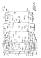
- FIGs. 10 through 12 illustrate the teachings and advantages of the present invention. Accordingly, a second edge flap reinforcing panel is hingedly connected to the first edge flap reinforcing panel. .
- the exemplary carton 1200 (shown in FIG. 11 ), is manufactured from a blank 1100.
- the blank 1100 is substantially identical to the blank 100, except for the addition of additional reinforcing panels, thus like numerals are used to identify like elements, with the addition of the prefix "1" before element numbers used to distinguish embodiment of FIG. 10 .
- the blank 1100 includes primary panels that include a top panel 1102, a first side panel 1104, a bottom panel 1106, and a second side panel 1108.
- the top panel 1102 is hingedly connected to the first side panel 1104 along fold line 1110, the first side panel 1104 is hingedly connected to the bottom panel 1106 along fold line 1112, and the bottom panel 1106 is hingedly connected to the second side panel 1108 along fold line 1114.
- the blank 1100 includes an edge flap 1116 that facilitates connecting the endmost primary panels to form a tubular structure.
- the edge flap 1116 is hingedly connected to the top panel 1102 along fold line 1118.
- Second edge flap reinforcing panels 1161a, 1161b are hingedly connected to the first edge flap reinforcing panels 1160a, 1160b along fold lines 1163a, 1163b.
- the first edge flap reinforcing panels 1160a, 1160b each have a reinforcing edge E1 and the second edge flap reinforcing panels 1161a, 1161b each have a reinforcing edge E3.
- the reinforcing edges E3 of the second edge flap reinforcing panels 1161 a, 1161b abut, but are separated or separable from, the top end flaps 1120a, 1120b.
- the side flap reinforcing panels 1164a, 1164b are folded along fold lines 1166a, 1166b and secured to respective side end flaps 1124a, 1124b by adhesive or other means for securing such that the reinforcing edges 1168a, 1168b are disposed adjacent and in reinforcing proximity to a portion of the edges 1150a, 1150b of the cutouts 1144a, 1144b, respectively.
- the second edge flap reinforcing panels 1161 a, 1161b are folded along fold lines 1163a, 1163b so as to be in a face contacting arrangement with the first edge flap reinforcing panels 1160a, 1160b such that the reinforcing edges E3 are disposed adjacent to the reinforcing edges E1 of the first edge flap reinforcing panels 1160a, 1160b.
- the inside surfaces of the second edge flap reinforcing panels 1161a, 1161b are in a face contacting arrangement with the inside surfaces of the first edge flap reinforcing panels 1160a, 1160b.
- the outside surfaces of the first and second edge flap reinforcing panels 1160a, 1161a can be in a face contacting arrangement.
- edge flap 1116 is folded so thai the inside surface of the edge flap 1116 is in a face contacting arrangement with the inside surface of top panel 1102.
- Adhesive is applied to the outside surface of the edge flap 1116 and, optionally, adhesive is applied to the outside surfaces of the first edge flap reinforcing panels 1160a, 1160b.
- the blank 1100 is then folded along fold line 1112 so that the inside surface of top panel 1102 is in a face contacting arrangement with the inside surface of second side panel 1108 and the outside surface of edge flap 1116 is thereby secured to the inside surface of second side panel 1108.
- the outside surfaces of the edge flap reinforcing panels 1160a, 1160b are in a face contacting arrangement with, and thereby secured to, the inside surfaces of the end flaps 1132a, 1132b, respectively.
- the first and second edge flap reinforcing panels 1160a, 1161a are dimensioned, shaped, and positioned so as to reinforce at least a portion of the edge 1154a formed in end flap 1132a without obstructing the cutout 1152a.
- the reinforcing edges E1, E3 of the first and second edge flap reinforcing panels 1160a, 1161a are positioned adjacent to the edge 1154a of the cutout 1152a to reinforce the upper or weight bearing portion of the end flaps 1132a (as best shown in FIG. 12 ).
- each end closure 1210, 1212 includes a handle H having edges that, in the first embodiment, are four-plies thick.
- at least the upper or weight bearing edge of the handle H is four plies thick.
- first and second edge flap reinforcing panels 1160a can be designed to provide an independent two-ply layer of reinforcement to the weight bearing edge of the handle opening 1136a to define a handle H.
- first and second edge flap reinforcing panels 1160a, 1161a can be designed to cooperate with one or more side flap reinforcing panels to provide multiple layers of reinforcement to at least the weight bearing edge of the handle opening 1136a to define a handle H.
- first and second edge flap reinforcing panels 1160a, 1161a overlaps one or more side flap reinforcing panels to provide multiple layers of reinforcement to the handle opening 1136a and thereby provide a thicker weight bearing edge of the handle H.
- the first edge flap reinforcing panel 1160a and the side flap reinforcing panel 1164a combine to provide a single layer of reinforcement to the weight bearing edge of the handle opening 1136a.
- the first edge flap reinforcing panel 1160a and the side flap reinforcing panel 1164a each reinforce approximately half of the upper or weight bearing edge of the handle opening 1136a.
- the second edge flap reinforcing panel 1161a overlaps the first edge flap reinforcing panel 1160 to additionally reinforce a half of the weight bearing edge of the handle opening 1136a. Accordingly, the first and second edge flap reinforcing panels 1160a, 1161 a extend to approximately the center of the handle H or otherwise to the distal edge E2 of the side end flap 1132a.
- each of the first and second edge flap reinforcing panels 1160a is approximately half of the width D2 of the top end flap 1120a, approximately half of the width of the end closure 1210, or approximately equal to the length of the side end flap 1132a.
- the length D1 of one or both of the first and second edge flap reinforcing panels 1160a, 1161a can be extended such that one or both of the first and second edge flap reinforcing panels 1160a, 1161 a reinforce a greater portion of the weight bearing edge of the handle opening 113a.
- the length D1 of the first and second edge flap reinforcing panels 1160a, 1161a can be approximately equal to a length D3, which is defined between the fold line 1118 and a far end of the handle opening 1136a or the handle H.
- first and second edge flap reinforcing panels 1160a, 1161a can overlap both side end flaps 1124a, 1132a so as to provide an independent two-ply layer or reinforcement to the weight bearing edge of the handle opening 1136a.
- These embodiments can optionally include side flap reinforcing panels, including those discussed in further detail below, to provide yet another ply of material to the handle H or the side flap reinforcing panels can be omitted.
- top, base, bottom, end, side, inner”, “outer”, “upper”, “middle”, “lower”, “front” and “rear” do not limit the respective walls of the carton to such orientation, but merely serve to distinguish these walls from one another.
- various embodiments demonstrate that the top, sides, and bottom panels may be hingedly connected to one another and secured into a tubular sleeve in any order that provides a top panel opposing a bottom panel and opposing side panels.
- hinged connection should not be construed as necessarily referring to a junction including a single hinge only; indeed, it is envisaged that hinged connection can be formed from one or more potentially disparate means for hingedly connecting materials.
- the exemplary cartons preferably have handles at both ends, although it is contemplated to include only one handle disposed in one of the end closures.
- any suitable means for securing sheet material may be used, including magnets, non-permanent adhesives, or hook and loop fasteners such as VELCRO ® , which is a trademark registered to Velcro Industries B.V.
- VELCRO ® which is a trademark registered to Velcro Industries B.V.
- handle openings of the invention are described as having removable centers, the centers may be only partially removable and may function as finger cushions after being partially detached from the edges of the handle openings.
Landscapes
- Engineering & Computer Science (AREA)
- Mechanical Engineering (AREA)
- Cartons (AREA)
Claims (9)
- Schachtel (1200) mit einer röhrenförmigen Struktur, die eine Vielzahl von Schachtelwandflächen umfasst, mit einer Deckenwandfläche (1102), einer Bodenwandfläche (1106), und erste und zweite Seitenwandflächen (1104, 1108), eine Kantenlasche (1116), die zwei der Schachtelwandflächen miteinander verbindet, und mindestens eine Endverschlußstruktur, welche umfasst:eine obere Endlasche (1120a, 1120b), die gelenkig mit der Deckenwandfläche (1102) verbunden ist und jene obere Endlasche eine Handöffnung (1136a, 1136b) umfasst;eine Bodenendlasche (1128a, 1128b), die mit der Bodenwandfläche (1106) gelenkig verbunden ist und;eine erste Kantenlaschen-Verstärkungswandfläche (1160a, 1160b), die gelenkig mit der Kantenlasche (1116) verbunden ist;wobei eine Verstärkungskante (E1) der ersten Kantenlaschen-Verstärkungswandfläche (1160a, 1160b) die angeordnet ist den angrenzenden Bereich der Handöffnung (1136a, 1136b) zu verstärken, um so wenigstens eine lasttragende Kante der Handöffnung zu verstärken, und dadurch gekennzeichnet, dasswenigstens eine der Enverschlußstrukturen zusätzlich eine zweite Kantenlaschen-Verstärkungswandfläche (1161a, 1161b) umfasst, die gelenkig mit der ersten Kantenlaschen-Verstärkungswandfläche verbunden ist, wobei eine Verstärkungskante (E3) der zweiten Kantenlaschen-Verstärkungswandfläche (1161a, 1161b) die angeordnet ist den angrenzenden Bereich der Handöffnung (1136a, 1136b) zu verstärken, um so wenigstens die lasttragende Kante der Handöffnung zu verstärken.
- Schachtel gemäß Anspruch 1, wobei wenigstens eine der Endverschlußstrukturen zusätzlich eine Seitenendlasche (1124a, 1124b, 1132a,1132b) umfasst, die gelenkig mit jeder der ersten und zweiten Seitenwandflächen (1104, 1108) verbunden ist, wobei jede Seitenendlasche eine Ausstanzung (1144a, 1144b, 1152a, 1152b) umfasst, wobei Endkanten (E2) der Seitenendlaschen zueinander benachbart sind, so dass die Ausstanzungen ausgerichtet sind, um die Handöffnung der wenigstens einen Endverschlußstruktur zu definieren.
- Schachtel gemäß Anspruch 1, wobei wenigstens eine Endverschlußstruktur zusätzlich eine Seitenendlasche (1124a, 1124b, 1132a, 1132b) umfasst, die gelenkig mit jeder der ersten und zweiten Seitenwandflächen (1104, 1108) verbunden ist, wobei jede Seitenendlasche eine Ausstanzung (1144a, 1144b, 1152a, 1152b) umfasst, mit Dimensionen komplementär zu den Dimensionen von wenigstens einem Teil der Handöffnung (1136a, 1136b) und wobei die obere Endlasche (1120a, 1120b) faltbar ist, um mindestens teilweise die Seitenendlaschen (1124a, 1124b, 1132a, 1132b) zu überlappen, so daß die Handöffnung (1136a, 1136b) in der oberen Endlasche deckungsgleich mit den Ausstanzungen in den ersten und zweiten seitlichen Endlaschen ist.
- Schachtel gemäß einem der Ansprüche 2 und 3, wobei wenigstens eine der Seitenendlaschen (1124a, 1124b) eine Seitenlaschen-Verstärkungswandfläche (1164a, 1164b) mit einer Verstärkungskante umfasst, wobei die Seitenlaschen-Verstärkungswandfläche faltbar ist, um die Verstärkungskante in einen angrenzenden Verstärkungsbereich zur Ausstanzung (1144a, 1144b) der wenigstens einer Seitenendlasche anzuordnen.
- Schachtel gemäß Anspruch 4, wobei die ersten und zweiten Kantenlaschen-Verstärkungswandflächen (1160a, 1160b, 1161 a, 1161 b) mit den Seitenlaschen-Verstärkungswandflächen (1164a, 1164b) zusammenwirken, um so wenigstens für die lasttragende Kante der Handöffnung (1136a, 1136b) eine Vielzahl von Verstärkungsschichten zur Verstärkung bereit zu stellen.
- Schachtel gemäß einem der Ansprüche 1 bis 5, wobei die Handöffnung (1136a, 1136b) durch eine Endloskante definiert wird.
- Zuschnitt (1100) zum Ausbilden einer Schachtel (1200), der eine Vielzahl von gelenkig verbundenen Hauptwandflächen zur Ausbildung der Wände beinhaltend, die eine Deckenwandfläche (1102), Bodenwandfläche (1106) und erste und zweite Seitenwandflächen (1104, 1108) einer röhrenförmigen Struktur; eine Kantenlasche (1116) die gelenkig mit einer der letzten Hauptwandflächen verbunden ist, wobei die Kantenlasche zur Verbindung der letzten Hauptwandflächen dient, um die röhrenförmige Struktur auszubilden, ferner eine Vielzahl von Endlaschen (1120a, 1120b, 1124a, 1124b, 1128a, 1128b, 1132a, 1132b) zur Ausbildung einer Endverschlußstruktur an einem Ende der Schachtel, wobei die Endlaschen eine obere Endlasche (1120a, 1120b) einschließt, an die Deckenwandfläche (1102) angelenkt ist und eine Bodenendlasche(1128a, 1128b) angelenkt ist an die Bodenwandfläche (1106), wobei jede der Vielzahl der Endlaschen gelenkig mit der entsprechenden Endkante der Hauptwandflächen verbunden, wobei die Endlaschen zur Ausbildung der Endverschlußstruktur dienen, und wobei wenigstens eine der Vielzahl der Endlaschen ein Merkmal (1136a, 1136b, 1144a, 1144b,1152a,1152b) beinhaltet um eine Handöffnung zu definieren, die durch den Endverschluß hindurch angeordnet ist, sowie eine erste Kantenlaschen-Verstärkungswandfläche (1160a, 1160b) die gelenkig verbunden ist mit der Kantenlasche (1116) wobei eine Verstärkungskante (E1) der ersten Kantenlaschen-Verstärkungswandfläche (1160a, 1160b) derart positioniert und dimensioniert ist, dass sie im angrenzenden Bereich der Handöffnung angeordnet ist, um wenigstens eine lasttragende Kante der Handöffnung beim Bilden der Endverschlußstruktur auszubilden, dadurch gegenzeichnet, dass eine zweite Kantenlaschen-Verstärkungswandfläche (1161 a, 1161 b) gelenkig mit der ersten Kantenlaschen-Verstärkungswandfläche verbunden ist, wobei eine Verstärkungskante (E3) der zweiten Kantenlaschen-Verstärkungswandfläche (1161a, 1161b) die angeordnet ist den angrenzenden Bereich der Handöffnung (1136a, 1136b) zu verstärken, um so wenigstens die lasttragende Kante der Handöffnung zu verstärken wenn die Endverschlußstruktur ausgebildet ist.
- Zuschnitt gemäß Anspruch 7, wobei die oberen Endlaschen (1120a, 1120b) eine Öffnung mit Endloskante (1136a, 1136b) beinhaltet um die Handöffnung zu definieren.
- Zuschnitt gemäß einem der Ansprüche 7 oder 8, wobei wenigstens zwei der Vielzahl der Endlaschen (1104,1108) eine komplementäre Ausstanzung (1144a, 1144b, 1152a, 1152b) zur Definierung der Handöffnung einschließt.
Applications Claiming Priority (3)
| Application Number | Priority Date | Filing Date | Title |
|---|---|---|---|
| US11/469,262 US20080054055A1 (en) | 2006-08-31 | 2006-08-31 | Carton with reinforced handle openings |
| US11/537,642 US7780067B2 (en) | 2006-08-31 | 2006-09-30 | Carton with reinforced handle openings |
| PCT/US2007/077096 WO2008027954A1 (en) | 2006-08-31 | 2007-08-29 | Carton with reinforced handle openings |
Publications (2)
| Publication Number | Publication Date |
|---|---|
| EP2064123A1 EP2064123A1 (de) | 2009-06-03 |
| EP2064123B1 true EP2064123B1 (de) | 2011-08-24 |
Family
ID=38824983
Family Applications (1)
| Application Number | Title | Priority Date | Filing Date |
|---|---|---|---|
| EP07814535A Not-in-force EP2064123B1 (de) | 2006-08-31 | 2007-08-29 | Karton mit verstärkten grifföffnungen |
Country Status (5)
| Country | Link |
|---|---|
| US (1) | US7780067B2 (de) |
| EP (1) | EP2064123B1 (de) |
| AT (1) | ATE521542T1 (de) |
| ES (1) | ES2372212T3 (de) |
| WO (1) | WO2008027954A1 (de) |
Cited By (1)
| Publication number | Priority date | Publication date | Assignee | Title |
|---|---|---|---|---|
| CN104114459A (zh) * | 2012-02-16 | 2014-10-22 | 印刷包装国际公司 | 带有加强把手的纸箱 |
Families Citing this family (36)
| Publication number | Priority date | Publication date | Assignee | Title |
|---|---|---|---|---|
| US7998047B2 (en) * | 2005-09-21 | 2011-08-16 | Graphic Packaging International, Inc. | Carton with reinforced handle |
| US7984843B2 (en) * | 2005-09-21 | 2011-07-26 | Graphic Packaging International, Inc. | Carton with reinforced handle |
| AU2006311674B2 (en) * | 2005-11-08 | 2010-12-16 | Graphic Packaging International, Inc. | Carton with reinforced handle |
| CN101395066A (zh) * | 2006-01-25 | 2009-03-25 | 印刷包装国际公司 | 用于纸箱的侧把手 |
| USD595129S1 (en) * | 2007-03-23 | 2009-06-30 | The Procter & Gamble Company | Box |
| US8628003B2 (en) * | 2010-09-25 | 2014-01-14 | Meadwestvaco Corporation | Product dispensing container, system and method with priming area |
| WO2012061175A2 (en) | 2010-11-01 | 2012-05-10 | Graphic Packaging International, Inc. | Carton with handle |
| WO2012094557A2 (en) | 2011-01-07 | 2012-07-12 | Graphic Packaging International, Inc. | Carton with handle |
| BR112013028448B1 (pt) | 2011-05-06 | 2020-07-21 | Graphic Packaging International, Llc | método de formar uma caixa de papelão |
| US9022217B2 (en) | 2011-05-06 | 2015-05-05 | Graphic Packaging International, Inc. | Carton with article protection feature |
| BR112014008672B1 (pt) | 2011-10-17 | 2020-09-08 | Graphic Packaging International, Llc | Embalagem de acondicionamento para acondicionar uma pluralidade de artigos, blanqueta para a formação de uma embalagem de acondicionamento, e método de formação de uma embalagem para acondicionar uma pluralidade de artigos |
| ES2567472T3 (es) | 2011-10-19 | 2016-04-22 | Graphic Packaging International, Inc. | Sistema y procedimiento para activar las características de protección de los artículos de una caja de cartón |
| US8757412B2 (en) | 2012-01-09 | 2014-06-24 | Monoflo International, Inc. | Foldable container with access opening |
| NZ631247A (en) * | 2012-04-27 | 2016-06-24 | Graphic Packaging Int Inc | Carton with insert |
| CN104271461A (zh) | 2012-05-03 | 2015-01-07 | 印刷包装国际公司 | 具有物品保护结构的纸箱 |
| CA2878915A1 (en) * | 2012-07-11 | 2014-01-16 | Meadwestvaco Packaging Systems, Llc | Carton with handle and blank therefor |
| ES2620435T3 (es) * | 2012-07-17 | 2017-06-28 | Graphic Packaging International, Inc. | Cajas de cartón con inserto |
| AU2013290750B2 (en) | 2012-07-17 | 2017-02-09 | Graphic Packaging International, Llc | Carton with article protection feature |
| US9840358B2 (en) | 2013-03-14 | 2017-12-12 | Graphic Packaging International, Inc. | Carton with article protection feature |
| BR112015025302B1 (pt) | 2013-04-10 | 2022-06-07 | Graphic Packaging International, Llc | Embalagem para alojar pelo menos um artigo, matriz para formar uma embalagem para alojar pelo menos um artigo, embalagem para alojar pelo menos um artigo, matriz para formar uma embalagem, e método para formar uma embalagem |
| US9701436B2 (en) | 2013-04-10 | 2017-07-11 | Graphic Packaging International, Inc. | Carton with article protection feature |
| MX2016008773A (es) | 2014-01-07 | 2016-09-08 | Graphic Packaging Int Inc | Portador para recipientes. |
| KR102509653B1 (ko) * | 2014-02-14 | 2023-03-14 | 리껭테크노스 가부시키가이샤 | 곤포 상자 |
| US9636882B2 (en) | 2014-08-19 | 2017-05-02 | Graphic Packaging International, Inc. | Carton with reinforced handle |
| CA2962625C (en) | 2014-10-27 | 2019-12-03 | Graphic Packaging International, Llc | Carton for articles |
| CN107148388B (zh) | 2014-10-30 | 2019-08-16 | 印刷包装国际有限责任公司 | 具有手柄的纸箱 |
| US9630736B2 (en) | 2014-11-17 | 2017-04-25 | Graphic Packaging International, Inc. | Carton with reinforcement features |
| EP3221232B1 (de) | 2014-11-17 | 2019-10-16 | Graphic Packaging International, LLC | Karton mit verstärkungsmerkmalen |
| US10351293B2 (en) * | 2016-12-20 | 2019-07-16 | Scott Douglas Bader | Container |
| US20230056914A1 (en) * | 2017-02-09 | 2023-02-23 | Westrock Shared Services, Llc | Crush-tolerant container and blank and method for forming the same |
| USRE49894E1 (en) * | 2017-02-09 | 2024-04-02 | Westrock Shared Services, Llc | Crush-tolerant container and blank and method for forming the same |
| KR20200002919A (ko) * | 2017-05-03 | 2020-01-08 | 웨스트락 패키징 시스템스, 엘엘씨 | 카톤 및 카톤을 위한 블랭크 |
| US12330840B2 (en) | 2019-02-04 | 2025-06-17 | Rehrig Pacific Company | Collapsible crate with retractable wall |
| JP7052909B1 (ja) * | 2020-12-16 | 2022-04-12 | 王子ホールディングス株式会社 | 包装箱 |
| USD993016S1 (en) | 2021-04-22 | 2023-07-25 | Graphic Packaging International, Llc | Carton |
| EP4514708A4 (de) | 2022-04-28 | 2026-04-15 | Graphic Packaging Int Llc | Karton für artikel |
Family Cites Families (18)
| Publication number | Priority date | Publication date | Assignee | Title |
|---|---|---|---|---|
| US2122654A (en) | 1936-10-05 | 1938-07-05 | Fort Wayne Corrugated Paper Co | Shipping container |
| US2196502A (en) | 1939-02-15 | 1940-04-09 | Container Corp | Container |
| US2702155A (en) | 1950-07-27 | 1955-02-15 | Int Paper Co | Shipping package |
| US3203613A (en) | 1962-11-19 | 1965-08-31 | St Regis Paper Co | Collapsible shipping carton |
| BE783042A (fr) * | 1971-05-06 | 1972-11-06 | Unilever Nv | Carton porte-bouteilles |
| US3756499A (en) * | 1972-03-09 | 1973-09-04 | Union Camp Corp | Box with five panel ends |
| US3933300A (en) | 1975-01-20 | 1976-01-20 | Hoerner Waldorf Corporation | Loin box with locking cover |
| US4046309A (en) | 1976-07-08 | 1977-09-06 | Olinkraft, Inc. | Shipping box |
| EP0084977A3 (de) | 1982-01-27 | 1984-08-01 | The Mead Corporation | Allseitig geschlossener Flaschenbehälter |
| US5072876A (en) | 1990-10-30 | 1991-12-17 | Riverwood International Corporation | Article carrier with side handles |
| US5350109A (en) | 1993-03-08 | 1994-09-27 | Labatt Brewing Company Limited | Paperboard carton handholds |
| GB2324293A (en) | 1997-04-19 | 1998-10-21 | Donald Wood | Carton with hinged lid panels. |
| GB9725242D0 (en) | 1997-11-28 | 1998-01-28 | Riverwood Int Corp | Paperboard carton with end wall handles |
| KR100612795B1 (ko) | 1998-06-11 | 2006-08-17 | 브리스톨-마이어스 스퀴브 파마 컴파니 | 결정성 에파비렌즈 |
| US6085959A (en) * | 1999-03-10 | 2000-07-11 | De Poan Pneumatic Corporation | Nailer magazine with blocking device |
| EP1320489A2 (de) | 2000-09-15 | 2003-06-25 | The Mead Corporation | Karton und entsprechender kartonzuschnitt |
| US6968992B2 (en) | 2003-10-24 | 2005-11-29 | Graphic Packaging International, Inc. | Handle and top handle reinforcement for a paperboard carton |
| US7743970B2 (en) * | 2005-06-13 | 2010-06-29 | Meadwestvaco Packaging Systems, Llc | Carton with reinforced end handles |
-
2006
- 2006-09-30 US US11/537,642 patent/US7780067B2/en not_active Expired - Fee Related
-
2007
- 2007-08-29 EP EP07814535A patent/EP2064123B1/de not_active Not-in-force
- 2007-08-29 AT AT07814535T patent/ATE521542T1/de not_active IP Right Cessation
- 2007-08-29 WO PCT/US2007/077096 patent/WO2008027954A1/en not_active Ceased
- 2007-08-29 ES ES07814535T patent/ES2372212T3/es active Active
Cited By (2)
| Publication number | Priority date | Publication date | Assignee | Title |
|---|---|---|---|---|
| CN104114459A (zh) * | 2012-02-16 | 2014-10-22 | 印刷包装国际公司 | 带有加强把手的纸箱 |
| CN104114459B (zh) * | 2012-02-16 | 2017-03-08 | 印刷包装国际公司 | 带有加强把手的纸箱 |
Also Published As
| Publication number | Publication date |
|---|---|
| EP2064123A1 (de) | 2009-06-03 |
| US20080203143A1 (en) | 2008-08-28 |
| ES2372212T3 (es) | 2012-01-17 |
| ATE521542T1 (de) | 2011-09-15 |
| WO2008027954A1 (en) | 2008-03-06 |
| US7780067B2 (en) | 2010-08-24 |
Similar Documents
| Publication | Publication Date | Title |
|---|---|---|
| US7780067B2 (en) | Carton with reinforced handle openings | |
| RU2346872C2 (ru) | Полностью закрытая обертываемая коробка | |
| US7743970B2 (en) | Carton with reinforced end handles | |
| JP4875709B2 (ja) | 強化取っ手付きカートン | |
| AU736949B2 (en) | Two-tier can package having divider panel and method of forming the same | |
| AU2002348083B2 (en) | Carton having a strap handle | |
| EP1515897B1 (de) | Kartonverpackung und zuschnitt | |
| US20080110967A1 (en) | Carton With Multiple Ply End Handle Reinforcement | |
| CN101432203B (zh) | 带有多层把手的纸箱 | |
| JP3186355U (ja) | 複数の物品を収容するためのパッケージ及びパッケージを形成するブランク | |
| US5297725A (en) | Carrier for stacked articles | |
| US6905066B2 (en) | Carton having a strap handle | |
| US20060081691A1 (en) | Fully enclosed carton | |
| US4295562A (en) | Article carrier and blank therefor | |
| EP2814757B1 (de) | Karton mit griff | |
| AU2002348083A1 (en) | Carton having a strap handle | |
| CA3111575C (en) | Carton with handle | |
| EP1855957B1 (de) | Getränkebehälter mit gurtartigem tragegriff | |
| EP3377413B1 (de) | Karton mit griff, zuschnitt und herstellungsverfahren | |
| EP2310291B1 (de) | Karton und kartonzuschnitt | |
| US20080054055A1 (en) | Carton with reinforced handle openings | |
| CA1164834A (en) | Article carrier and blank therefor | |
| EP1135296B1 (de) | Hochbeanspruchbarer tragbehälter | |
| CA3184397A1 (en) | Article carrier and blank therefor | |
| HK1075876B (en) | Carton and carton blank |
Legal Events
| Date | Code | Title | Description |
|---|---|---|---|
| PUAI | Public reference made under article 153(3) epc to a published international application that has entered the european phase |
Free format text: ORIGINAL CODE: 0009012 |
|
| 17P | Request for examination filed |
Effective date: 20090209 |
|
| AK | Designated contracting states |
Kind code of ref document: A1 Designated state(s): AT BE BG CH CY CZ DE DK EE ES FI FR GB GR HU IE IS IT LI LT LU LV MC MT NL PL PT RO SE SI SK TR |
|
| AX | Request for extension of the european patent |
Extension state: AL BA HR MK RS |
|
| 17Q | First examination report despatched |
Effective date: 20100121 |
|
| RAP1 | Party data changed (applicant data changed or rights of an application transferred) |
Owner name: MEADWESTVACO PACKAGING SYSTEMS LLC |
|
| GRAP | Despatch of communication of intention to grant a patent |
Free format text: ORIGINAL CODE: EPIDOSNIGR1 |
|
| RIN1 | Information on inventor provided before grant (corrected) |
Inventor name: HOLLEY, JOHN, M, JR |
|
| RAP1 | Party data changed (applicant data changed or rights of an application transferred) |
Owner name: MEADWESTVACO PACKAGING SYSTEMS, LLC |
|
| GRAS | Grant fee paid |
Free format text: ORIGINAL CODE: EPIDOSNIGR3 |
|
| GRAA | (expected) grant |
Free format text: ORIGINAL CODE: 0009210 |
|
| AK | Designated contracting states |
Kind code of ref document: B1 Designated state(s): AT BE BG CH CY CZ DE DK EE ES FI FR GB GR HU IE IS IT LI LT LU LV MC MT NL PL PT RO SE SI SK TR |
|
| REG | Reference to a national code |
Ref country code: GB Ref legal event code: FG4D |
|
| REG | Reference to a national code |
Ref country code: CH Ref legal event code: EP |
|
| REG | Reference to a national code |
Ref country code: IE Ref legal event code: FG4D |
|
| REG | Reference to a national code |
Ref country code: DE Ref legal event code: R096 Ref document number: 602007016660 Country of ref document: DE Effective date: 20111027 |
|
| REG | Reference to a national code |
Ref country code: NL Ref legal event code: T3 |
|
| PG25 | Lapsed in a contracting state [announced via postgrant information from national office to epo] |
Ref country code: MT Free format text: LAPSE BECAUSE OF FAILURE TO SUBMIT A TRANSLATION OF THE DESCRIPTION OR TO PAY THE FEE WITHIN THE PRESCRIBED TIME-LIMIT Effective date: 20110824 |
|
| REG | Reference to a national code |
Ref country code: ES Ref legal event code: FG2A Ref document number: 2372212 Country of ref document: ES Kind code of ref document: T3 Effective date: 20120117 |
|
| LTIE | Lt: invalidation of european patent or patent extension |
Effective date: 20110824 |
|
| PG25 | Lapsed in a contracting state [announced via postgrant information from national office to epo] |
Ref country code: FI Free format text: LAPSE BECAUSE OF FAILURE TO SUBMIT A TRANSLATION OF THE DESCRIPTION OR TO PAY THE FEE WITHIN THE PRESCRIBED TIME-LIMIT Effective date: 20110824 Ref country code: LT Free format text: LAPSE BECAUSE OF FAILURE TO SUBMIT A TRANSLATION OF THE DESCRIPTION OR TO PAY THE FEE WITHIN THE PRESCRIBED TIME-LIMIT Effective date: 20110824 Ref country code: SE Free format text: LAPSE BECAUSE OF FAILURE TO SUBMIT A TRANSLATION OF THE DESCRIPTION OR TO PAY THE FEE WITHIN THE PRESCRIBED TIME-LIMIT Effective date: 20110824 Ref country code: PT Free format text: LAPSE BECAUSE OF FAILURE TO SUBMIT A TRANSLATION OF THE DESCRIPTION OR TO PAY THE FEE WITHIN THE PRESCRIBED TIME-LIMIT Effective date: 20111226 Ref country code: IS Free format text: LAPSE BECAUSE OF FAILURE TO SUBMIT A TRANSLATION OF THE DESCRIPTION OR TO PAY THE FEE WITHIN THE PRESCRIBED TIME-LIMIT Effective date: 20111224 |
|
| REG | Reference to a national code |
Ref country code: AT Ref legal event code: MK05 Ref document number: 521542 Country of ref document: AT Kind code of ref document: T Effective date: 20110824 |
|
| PG25 | Lapsed in a contracting state [announced via postgrant information from national office to epo] |
Ref country code: AT Free format text: LAPSE BECAUSE OF FAILURE TO SUBMIT A TRANSLATION OF THE DESCRIPTION OR TO PAY THE FEE WITHIN THE PRESCRIBED TIME-LIMIT Effective date: 20110824 Ref country code: LV Free format text: LAPSE BECAUSE OF FAILURE TO SUBMIT A TRANSLATION OF THE DESCRIPTION OR TO PAY THE FEE WITHIN THE PRESCRIBED TIME-LIMIT Effective date: 20110824 Ref country code: CY Free format text: LAPSE BECAUSE OF FAILURE TO SUBMIT A TRANSLATION OF THE DESCRIPTION OR TO PAY THE FEE WITHIN THE PRESCRIBED TIME-LIMIT Effective date: 20110824 Ref country code: PL Free format text: LAPSE BECAUSE OF FAILURE TO SUBMIT A TRANSLATION OF THE DESCRIPTION OR TO PAY THE FEE WITHIN THE PRESCRIBED TIME-LIMIT Effective date: 20110824 Ref country code: SI Free format text: LAPSE BECAUSE OF FAILURE TO SUBMIT A TRANSLATION OF THE DESCRIPTION OR TO PAY THE FEE WITHIN THE PRESCRIBED TIME-LIMIT Effective date: 20110824 Ref country code: GR Free format text: LAPSE BECAUSE OF FAILURE TO SUBMIT A TRANSLATION OF THE DESCRIPTION OR TO PAY THE FEE WITHIN THE PRESCRIBED TIME-LIMIT Effective date: 20111125 |
|
| PG25 | Lapsed in a contracting state [announced via postgrant information from national office to epo] |
Ref country code: MC Free format text: LAPSE BECAUSE OF NON-PAYMENT OF DUE FEES Effective date: 20110831 Ref country code: BE Free format text: LAPSE BECAUSE OF FAILURE TO SUBMIT A TRANSLATION OF THE DESCRIPTION OR TO PAY THE FEE WITHIN THE PRESCRIBED TIME-LIMIT Effective date: 20110824 |
|
| REG | Reference to a national code |
Ref country code: CH Ref legal event code: PL |
|
| PG25 | Lapsed in a contracting state [announced via postgrant information from national office to epo] |
Ref country code: LI Free format text: LAPSE BECAUSE OF NON-PAYMENT OF DUE FEES Effective date: 20110831 Ref country code: CZ Free format text: LAPSE BECAUSE OF FAILURE TO SUBMIT A TRANSLATION OF THE DESCRIPTION OR TO PAY THE FEE WITHIN THE PRESCRIBED TIME-LIMIT Effective date: 20110824 Ref country code: CH Free format text: LAPSE BECAUSE OF NON-PAYMENT OF DUE FEES Effective date: 20110831 Ref country code: SK Free format text: LAPSE BECAUSE OF FAILURE TO SUBMIT A TRANSLATION OF THE DESCRIPTION OR TO PAY THE FEE WITHIN THE PRESCRIBED TIME-LIMIT Effective date: 20110824 |
|
| REG | Reference to a national code |
Ref country code: IE Ref legal event code: MM4A |
|
| PG25 | Lapsed in a contracting state [announced via postgrant information from national office to epo] |
Ref country code: EE Free format text: LAPSE BECAUSE OF FAILURE TO SUBMIT A TRANSLATION OF THE DESCRIPTION OR TO PAY THE FEE WITHIN THE PRESCRIBED TIME-LIMIT Effective date: 20110824 Ref country code: RO Free format text: LAPSE BECAUSE OF FAILURE TO SUBMIT A TRANSLATION OF THE DESCRIPTION OR TO PAY THE FEE WITHIN THE PRESCRIBED TIME-LIMIT Effective date: 20110824 |
|
| PG25 | Lapsed in a contracting state [announced via postgrant information from national office to epo] |
Ref country code: DK Free format text: LAPSE BECAUSE OF FAILURE TO SUBMIT A TRANSLATION OF THE DESCRIPTION OR TO PAY THE FEE WITHIN THE PRESCRIBED TIME-LIMIT Effective date: 20110824 |
|
| PLBE | No opposition filed within time limit |
Free format text: ORIGINAL CODE: 0009261 |
|
| STAA | Information on the status of an ep patent application or granted ep patent |
Free format text: STATUS: NO OPPOSITION FILED WITHIN TIME LIMIT |
|
| PG25 | Lapsed in a contracting state [announced via postgrant information from national office to epo] |
Ref country code: IE Free format text: LAPSE BECAUSE OF NON-PAYMENT OF DUE FEES Effective date: 20110829 |
|
| 26N | No opposition filed |
Effective date: 20120525 |
|
| REG | Reference to a national code |
Ref country code: DE Ref legal event code: R097 Ref document number: 602007016660 Country of ref document: DE Effective date: 20120525 |
|
| PG25 | Lapsed in a contracting state [announced via postgrant information from national office to epo] |
Ref country code: LU Free format text: LAPSE BECAUSE OF NON-PAYMENT OF DUE FEES Effective date: 20110829 |
|
| PG25 | Lapsed in a contracting state [announced via postgrant information from national office to epo] |
Ref country code: BG Free format text: LAPSE BECAUSE OF FAILURE TO SUBMIT A TRANSLATION OF THE DESCRIPTION OR TO PAY THE FEE WITHIN THE PRESCRIBED TIME-LIMIT Effective date: 20111124 |
|
| PG25 | Lapsed in a contracting state [announced via postgrant information from national office to epo] |
Ref country code: TR Free format text: LAPSE BECAUSE OF FAILURE TO SUBMIT A TRANSLATION OF THE DESCRIPTION OR TO PAY THE FEE WITHIN THE PRESCRIBED TIME-LIMIT Effective date: 20110824 |
|
| PG25 | Lapsed in a contracting state [announced via postgrant information from national office to epo] |
Ref country code: HU Free format text: LAPSE BECAUSE OF FAILURE TO SUBMIT A TRANSLATION OF THE DESCRIPTION OR TO PAY THE FEE WITHIN THE PRESCRIBED TIME-LIMIT Effective date: 20110824 |
|
| PGFP | Annual fee paid to national office [announced via postgrant information from national office to epo] |
Ref country code: NL Payment date: 20130826 Year of fee payment: 7 Ref country code: ES Payment date: 20130826 Year of fee payment: 7 Ref country code: DE Payment date: 20130828 Year of fee payment: 7 |
|
| PGFP | Annual fee paid to national office [announced via postgrant information from national office to epo] |
Ref country code: FR Payment date: 20130819 Year of fee payment: 7 Ref country code: GB Payment date: 20130827 Year of fee payment: 7 |
|
| PGFP | Annual fee paid to national office [announced via postgrant information from national office to epo] |
Ref country code: IT Payment date: 20130822 Year of fee payment: 7 |
|
| REG | Reference to a national code |
Ref country code: DE Ref legal event code: R119 Ref document number: 602007016660 Country of ref document: DE |
|
| REG | Reference to a national code |
Ref country code: NL Ref legal event code: V1 Effective date: 20150301 |
|
| GBPC | Gb: european patent ceased through non-payment of renewal fee |
Effective date: 20140829 |
|
| PG25 | Lapsed in a contracting state [announced via postgrant information from national office to epo] |
Ref country code: NL Free format text: LAPSE BECAUSE OF NON-PAYMENT OF DUE FEES Effective date: 20150301 Ref country code: IT Free format text: LAPSE BECAUSE OF NON-PAYMENT OF DUE FEES Effective date: 20140829 |
|
| REG | Reference to a national code |
Ref country code: DE Ref legal event code: R119 Ref document number: 602007016660 Country of ref document: DE Effective date: 20150303 |
|
| REG | Reference to a national code |
Ref country code: FR Ref legal event code: ST Effective date: 20150430 |
|
| PG25 | Lapsed in a contracting state [announced via postgrant information from national office to epo] |
Ref country code: DE Free format text: LAPSE BECAUSE OF NON-PAYMENT OF DUE FEES Effective date: 20150303 Ref country code: GB Free format text: LAPSE BECAUSE OF NON-PAYMENT OF DUE FEES Effective date: 20140829 |
|
| PG25 | Lapsed in a contracting state [announced via postgrant information from national office to epo] |
Ref country code: FR Free format text: LAPSE BECAUSE OF NON-PAYMENT OF DUE FEES Effective date: 20140901 |
|
| REG | Reference to a national code |
Ref country code: ES Ref legal event code: FD2A Effective date: 20160226 |
|
| PG25 | Lapsed in a contracting state [announced via postgrant information from national office to epo] |
Ref country code: ES Free format text: LAPSE BECAUSE OF NON-PAYMENT OF DUE FEES Effective date: 20140830 |