EP2064517B1 - Prodede de detection d'un detail geometrique pour definir la position dans l'espace d'une jante de roue par rapport a un appareil de mesure ainsi que procede et dispositif pour definir la position dans l'espace d'une jante de roue par rapport a un appareil - Google Patents
Prodede de detection d'un detail geometrique pour definir la position dans l'espace d'une jante de roue par rapport a un appareil de mesure ainsi que procede et dispositif pour definir la position dans l'espace d'une jante de roue par rapport a un appareil Download PDFInfo
- Publication number
- EP2064517B1 EP2064517B1 EP07802894A EP07802894A EP2064517B1 EP 2064517 B1 EP2064517 B1 EP 2064517B1 EP 07802894 A EP07802894 A EP 07802894A EP 07802894 A EP07802894 A EP 07802894A EP 2064517 B1 EP2064517 B1 EP 2064517B1
- Authority
- EP
- European Patent Office
- Prior art keywords
- wheel rim
- measuring
- wheel
- measuring device
- image
- Prior art date
- Legal status (The legal status is an assumption and is not a legal conclusion. Google has not performed a legal analysis and makes no representation as to the accuracy of the status listed.)
- Not-in-force
Links
Images




Classifications
-
- G—PHYSICS
- G01—MEASURING; TESTING
- G01B—MEASURING LENGTH, THICKNESS OR SIMILAR LINEAR DIMENSIONS; MEASURING ANGLES; MEASURING AREAS; MEASURING IRREGULARITIES OF SURFACES OR CONTOURS
- G01B11/00—Measuring arrangements characterised by the use of optical techniques
- G01B11/26—Measuring arrangements characterised by the use of optical techniques for measuring angles or tapers; for testing the alignment of axes
- G01B11/275—Measuring arrangements characterised by the use of optical techniques for measuring angles or tapers; for testing the alignment of axes for testing wheel alignment
- G01B11/2755—Measuring arrangements characterised by the use of optical techniques for measuring angles or tapers; for testing the alignment of axes for testing wheel alignment using photoelectric detection means
-
- G—PHYSICS
- G01—MEASURING; TESTING
- G01B—MEASURING LENGTH, THICKNESS OR SIMILAR LINEAR DIMENSIONS; MEASURING ANGLES; MEASURING AREAS; MEASURING IRREGULARITIES OF SURFACES OR CONTOURS
- G01B2210/00—Aspects not specifically covered by any group under G01B, e.g. of wheel alignment, caliper-like sensors
- G01B2210/10—Wheel alignment
- G01B2210/14—One or more cameras or other optical devices capable of acquiring a two-dimensional image
- G01B2210/146—Two or more cameras imaging the same area
-
- G—PHYSICS
- G01—MEASURING; TESTING
- G01B—MEASURING LENGTH, THICKNESS OR SIMILAR LINEAR DIMENSIONS; MEASURING ANGLES; MEASURING AREAS; MEASURING IRREGULARITIES OF SURFACES OR CONTOURS
- G01B2210/00—Aspects not specifically covered by any group under G01B, e.g. of wheel alignment, caliper-like sensors
- G01B2210/10—Wheel alignment
- G01B2210/26—Algorithms, instructions, databases, computerized methods and graphical user interfaces employed by a user in conjunction with the wheel aligner
Definitions
- the invention relates to a method for finding a geometry detail for determining the spatial position of a wheel rim to a measuring device, a measuring method and a measuring device for determining the spatial position of a wheel rim and a chassis measuring device, wherein such a method for finding a geometry detail for determining the spatial position a wheel rim is used to a measuring device.
- a measuring method and a measuring device for determining the spatial position of a wheel rim and a chassis measuring device are known. This measuring method is based on the recognition of a wheel rim geometry detail, for example of the rim flange, its evaluation with regard to the position in space and the combination of the results for an axle measurement.
- geometry details for determining their spatial position can be found to a measuring device.
- the geometric detail is usually a circular or ellipsoidal, toroidal or a point or line-shaped element of the wheel rim.
- the geometry detail does not have to be part of a wheel rim, but may also be a target fixed to the wheel rim or wheel hub, or an object attached to the wheel rim or wheel hub, for example a wheel cover or the like. be, or a steel plate or the like, as it is attached, for example, in motorsport as a measuring wheel on the wheel hub.
- wheel rim geometry detail is used in this description below, it includes both geometry details on the wheel rim itself and on the wheel rim or on the wheel hub mounted targets or objects.
- At least one measuring camera of a measuring device of a chassis measuring device or a motor vehicle test track is first aligned with a wheel rim and an image of the wheel rim is detected. Subsequently, a plurality of geometry details are determined in the image of the wheel rim, so that it is not clear which one of the geometric details is most suitable for determining the spatial position of the wheel rim relative to the measuring device. Namely, wheel rims of a motor vehicle wheel often have more than just one geometry detail that is useful for the measuring method. Therefore, in the next method step, one of the detected geometry details is selected for the determination of the spatial position of the wheel rim to the measuring device.
- the rim flange is to be preferred as the preferred for the subsequent measurement method Geometriedetail, if it has been determined on the image of the wheel rim.
- other evaluation criteria can be used, for example, the preference of toroidal geometry with respect to point or line geometries, the visibility or contrast ratio of the geometry detail, or the largest possible diameter for toroidal geometry details.
- different rim geometry details of a wheel rim can in fact be suitable for a subsequent method for determining the spatial position of a wheel rim relative to a measuring device.
- two wheel rims are considered simultaneously, namely by at least one measuring camera of a measuring device.
- the measuring cameras of the two measuring devices are aligned with the two wheel rims and then at least one image of the wheel rim is detected by each measuring camera.
- the four wheel rims of a motor vehicle are each detected by a measuring device with at least one camera by aligning the measuring cameras of the measuring devices on a respective wheel rim and then by at least one image of each wheel rim is detected by the measuring cameras.
- additional measuring devices with measuring cameras for the wheel rims of the third and each further axle can also be provided for three- or multi-axle vehicles.
- multiple geometry details can be determined in the image of a wheel rim and a determined geometry detail used to determine the spatial location of that rim to the gage. Subsequently, this selected geometry detail can be checked to see if it is also present in the measuring camera images of the other measuring devices. If so, this selected geometry detail is suitable for determining the spatial location of the wheel rims to the gauges. If not, an attempt can be made to locate this geometry detail on the other wheel rim images or, if this is not possible, another geometry detail can be selected. An assumption of the optimal geometry details for all wheel rims of the motor vehicle on the measuring stand can thus be checked and carried out automatically in one variant.
- the geometry details of the wheel rims can be filtered such that only those are determined and provided for selection that occur in all images of the wheel rims, and that the optimum geometry detail is finally selected from these pre-filtered geometry details.
- This filter function can lead to a common geometry detail of all wheel rims being found and unambiguously determined to be the best according to the evaluation criteria, so that no further selection is required.
- At least one measuring camera of the measuring device is first aligned with a wheel rim and captured an image of this wheel rim. Subsequently, a partial region is selected in the acquired image of the wheel rim, this takes place in particular if no geometry detail is recorded in the acquired image can be detected, for example. As a result of damage or contamination of the wheel rim or as a result of visual limitations, for example. Shadow distributions.
- a pre-selection is made, on the basis of which at least one detail of the geometry in the image of the wheel rim can be recognized for determining its spatial position relative to the measuring device.
- This non-inventive method ensures that a required for the subsequent determination of the spatial position of the wheel rim to the measuring device geometry detail is determined even if such Geomtriedetail on the captured image of the wheel rim is initially not recognizable.
- the chassis measuring device or the motor vehicle test lane is given an important assistance, without which it would not be possible to determine the spatial position of the wheel rim relative to the measuring device.
- At least one point is determined for selecting a partial region in the image of the wheel rim, which represents, for example, a screw, a bore or a valve of the wheel rim.
- Tori are generally better suited for the subsequent determination of the spatial position of the wheel rim to the measuring device, at least three points can be determined to select a portion in the image of the wheel rim through which runs a circular or ellipsoidal, toroidal geometric detail and on the circular Geometry detail of the displayed image are.
- the at least three specific points are equidistant, i. H. are evenly spaced on the perimeter of the geometry detail.
- At least one rectangular area around a circular or ellipsoidal geometry detail is determined for selecting a partial area in the image of the wheel rim.
- the image of the wheel rim or the images of the wheel rim and / or the plurality of determined geometry details can be displayed on a display device, in particular on a screen, so as to give the user visual feedback and the possibility of interaction.
- the selection of a determined geometry detail and / or a sub-area with image of the wheel rim is user-controlled, via a display device, in particular via a screen and / or an input device, in particular a mouse or a keyboard.
- the user can interactively make a selection or select a subarea via the display device and the input device.
- At least the image of one of the stereo cameras of a measuring head is displayed on the display device, on the basis of the input device corresponding interactions can be performed. For some applications it is necessary to display and interactively edit the images of both stereo cameras of a measuring head.
- the user selects one of several suitable geometry details offered by the measuring system from a wheel rim of a wheel on the displayed image.
- the user selects an area in which the measuring system is to determine a rim geometry detail
- the selection of a determined geometry detail and / or a subarea in the image of the wheel rim can be automated or computer-controlled using one or more evaluation criteria in a variant, whereby the method is automated and user intervention can be dispensed with.
- the wheel alignment device evaluates the at least one determined geometry detail in the image of the wheel rim, and this evaluation can be displayed on the display device. This can already during the procedure a Statement about the determined geometry detail and thus on the expected quality of the results of the determination of the spatial position of a wheel rim are made to a meter.
- the most suitable geometry detail for determining the spatial position of a wheel rim relative to a measuring device is a torus, in particular the torus of the rim flange.
- the invention also includes a method for determining the spatial position of a wheel rim to a measuring device having at least one camera, wherein the wheel rim is in the field of view of the camera.
- a model is initially provided which describes a model body of a locatable wheel rim geometric detail as well as the spatial position of the model body to the measuring instrument by model parameters. Then, an image of the wheel rim geometry detail of the wheel rim is captured with the camera and a method for finding a geometry detail for determining the spatial location of a wheel rim to a measuring device of the type described above is performed.
- fitting or fitting model body mapping to the image of the wheel rim geometry detail by modifying model parameters of the model, and tracking the model parameter changes in fitting, with data relating to the location of the model body of the wheel rim Geometry details reproduce the spatial location of the wheel rim geometry detail, and thus the wheel rim itself, when the model body map resulting from the model parameters of the wheel rim geometry detail matches the captured image of the wheel rim geometry detail within predetermined tolerance limits.
- a further advantageous embodiment of the method according to the invention is characterized in that the model body is a so-called Schmiegetorus or a 3D-CAD representation. While the Schmiegetorus is the simplest form of a 3D model for the rim contour, a 3D CAD representation of the rim in question can be used, which can also achieve good results.
- a further advantageous embodiment of the method according to the invention is characterized in that in the case of Schmiegetorus model parameters of the model, a main radius R and a minor radius r of the torus, a position c of the torus center, a normal vector n of the plane of rotation of the torus and a position z of the projection center of a pinhole camera are with whom the Schmiegetorus is considered. From these model parameters of the Schmiegetorus some of the actual dimensions of the wheel rim and the arrangement of the pinhole camera are known, so that the number of unknowns in the resulting optimization problem is advantageously reduced, so that adjusting the image of the Schmiegetorus to the image of the actual Rim is relieved.
- a further advantageous embodiment of the method according to the invention is characterized in that the wheel rim Geometriedetail is the rim edge contour.
- the wheel rim contour is a preferred feature because there is reasonably good contrast between the wheel rim and the tire.
- a further advantageous embodiment of the method according to the invention is characterized in that the wheel rim contour is detected with two cameras, which are directed at different angles on the wheel.
- a camera would be sufficient as a basis for carrying out the measurements according to the invention.
- two cameras are beneficial in terms of error correction to obtain a higher degree of accuracy of the measurement.
- a further advantageous embodiment of the method according to the invention is characterized in that the image of the wheel rim for determining a rotational angle reference point on the rim and for segmenting the rim flange contour along the rim circumference is added.
- the contour determination can thus take sufficient account of the local lighting behavior and the local rim flange geometry.
- a further advantageous embodiment of the method according to the invention is characterized in that the position of the valve is used to determine the angle of rotation reference point on the rim.
- the valve is the most outstanding feature of a vehicle wheel, indicating the rotational position of the wheel.
- a marker could also be used to mark a turning angle point on the rim, again requiring contact with the wheel. In practice it has been found that the localization of the valve is sufficient for the purposes of the present measurement.
- the valve can be selected or in the case in that initially no marker is found, a partial region of the image of the wheel rim is selected, in which or based on which a suitable marker can be determined in a following step. This can also be done user - or computer controlled on the basis of specifiable criteria.
- a further advantageous embodiment of the method according to the invention is characterized in that a pre-segmentation and a fine segmentation (sub-pixel segmentation) is performed for the segmentation of the rim circumference.
- This procedure advantageously makes it possible to simplify the required arithmetic operations in order to be able to carry out the segmentation with sufficient accuracy.
- a further advantageous embodiment of the method according to the invention is characterized in that the data relating to the model parameters of the model which define the spatial position of the wheel rim when the image of the model body of the wheel rim geometry detail matches the detected image of the wheel rim geometry detail is output or displayed become.
- a further advantageous embodiment of the method according to the invention is characterized by the following steps: starting the image acquisition; Segmentation of the rim, wherein also a segmentation of the valve of the motor vehicle wheel takes place; Segmentation of the rim edge; Checking the result of the segmentation on an existing and unambiguous result and optionally selecting the most suitable result and optionally selecting a portion of an image of the rim for a post-segmentation; Reconstruction of the 3D position of the valve taking into account the external camera parameters; Reconstruction of the position of the edge of the rim; Displaying the result of the calculation, namely the normal vector of the rim edge plane and / or storing the same for further billing.
- a further advantageous embodiment of the method according to the invention is characterized in that after starting the image acquisition is first checked whether the illumination is sufficient for the measurement, and that the lighting is adjusted accordingly.
- a further advantageous embodiment of the method according to the invention is characterized in that the adjustment comprises a greater or lesser brightness of the light for the illumination.
- the measuring device for determining the spatial position of a wheel rim to the measuring device having at least one camera, wherein the wheel rim is in the field of view of the camera is characterized by a computer which is programmed to perform one of the methods described above.
- An advantageous embodiment of the measuring device according to the invention is characterized in that two cameras are provided in the above measuring device, which detect the wheel rim contour and are directed at different angles on the wheel:
- a further advantageous embodiment of the measuring device according to the invention is characterized in that it comprises an optical sensor, a lens, an aperture setting device and a focus adjusting device per camera, and that the mounting position of the sensor and the lens, the aperture setting and focus adjustment are pre-adjusted.
- a further advantageous embodiment of the measuring device according to the invention is characterized in that in zoom lenses also the set focal length is pre-adjusted.
- a further advantageous embodiment of the measuring device according to the invention is characterized in that an output or display device for outputting or displaying the data with respect to the model parameters of the model, which define the spatial position of the wheel rim, when the image of the model body of the wheel rim Geometriedetails with captured image of the wheel rim geometry details is provided. This makes it easier to set up the measuring station, because the fine adjustment of the reference system can be performed again at any time.
- the advantages of the measuring device according to the invention and its embodiments correspond to the advantage of the method according to the invention and its embodiments, as described above.
- the inventive method for wheel alignment on motor vehicles is characterized in that one of the above method for determining the spatial position of a wheel rim is performed to a measuring device on the wheels of the motor vehicle that the relative positions of the measuring devices are determined to perform the measurements that the measurement results of the measurements on the wheels of the motor vehicle are converted into wheel position values, taking into account the relative positions of the measuring devices, and that the wheel position values are output or displayed.
- An advantageous embodiment of the method according to the invention is characterized in that the relative positions of the measuring devices for carrying out the measurements are determined by an adjustable mounting of the measuring devices at a measuring station.
- a further advantageous embodiment of the method according to the invention is characterized in that the relative positions of the measuring devices for carrying out the measurements are determined by a reference system which is arranged on the measuring devices.
- a further advantageous embodiment of the method according to the invention is characterized by the following steps: carrying out the measurements of the individual measuring devices; Reading the measurement results into a computer; Calculate the transformation matrix from the results of the reference system measurement; Transforming the results of the measuring instruments parallel to the axes of the computer coordinate system; Converting the vectors into the computer coordinate system via offset angles and distances in the reference measurement system; Determining the wheel position values in the computing coordinate system by evaluating the position of the result vectors relative to one another for calculating the corresponding chassis measurement values; Passing the results on the wheel position angle values to a display device and / or storing the same for further use.
- An inventive wheel alignment device and a test line according to the invention for motor vehicles is characterized by measuring devices for determining the spatial position of a wheel rim to a measuring device on the wheels of the motor vehicle, which are positioned on a measuring station such that a measuring device is assigned in each case one of the wheels of the motor vehicle the relative positions of the gauges in performing the measurements are determined, a computer that converts the measurement results of the measurements on the wheels of the motor vehicle into wheel position values, taking into account the relative positions of the gauges, and a display / output device that outputs or displays the wheel position values ,
- a motor vehicle test lane comprises a chassis tester and a brake test bench and normally also a track plate, which however can advantageously be dispensed with in the motor vehicle test lane according to the invention.
- the motor vehicle test lane is often extended by a joint play tester, which in turn is integrated in a pit or a lift. In some cases, the motor vehicle test is still extended to an exhaust gas tester and a headlamp adjuster.
- An advantageous embodiment of the wheel alignment measuring device or test line according to the invention is characterized in that the relative positions of the measuring devices for carrying out the measurements are determined by an adjustable mounting of the measuring devices at a measuring station.
- An advantageous embodiment of the chassis measuring device or test line according to the invention is characterized in that the relative positions of the measuring devices for carrying out the measurements are determined by a reference system which is arranged on the measuring devices.
- An advantageous embodiment of the wheel alignment measuring device or test line according to the invention is characterized in that when assembling two cameras in a measuring device to a stereo measuring system, the cameras are calibrated relative to the coordinate system of the measuring device.
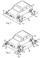
- FIG. 1 shows a measuring station 10, on which a motor vehicle 12 is, whose chassis is to be measured.
- Four measuring devices are fixedly arranged on the measuring station 10, of which three measuring devices 14, 16, 18 are shown, while the fourth measuring device is covered by the motor vehicle 12.
- the measuring devices 14, 16, 18 each comprise a base plate 30 and two cameras 32, 34, which are directed at different angles to the associated wheel 36 of the motor vehicle 12.
- the measuring devices 14, 16, 18 are permanently mounted on the measuring station 10, wherein the relative angular positions of the measuring devices with each other and their distances are determined during assembly and then remain unchanged.
- FIG. 2 shows a measuring station 20 with the motor vehicle 12, again three measuring devices 24, 26, 28 are shown, while the fourth measuring device is covered by the motor vehicle 12.
- each reference system measuring head such as the reference system measuring head 50, has two transceiver units 56, 58 facing the reference system measuring head 52, which is opposite to the longitudinal direction of the vehicle 12, or the reference system measuring head 54, which is opposite to the vehicle 12 are.
- the calibration of the stereo measuring system comprises the calibration of the "internal camera parameters" and the calibration of the installation situation of the measuring devices 24, 26, 28.
- “internal parameters” designates all parameters which are camera-specific, ie are defined by the assembly of the camera. Internal parameters are determined by the mounting position of the optical sensor, the lens and its mounting position, the aperture setting and focus adjustment. With zoom lenses, the set focal length is also crucial. The internal parameters can be considered as constant as long as no mechanical change is made to the camera or the lens setting is changed. The parameters are determined by means of completely known objects. Preferably, currently the calibration with a 3D object, such as a provided with enough prominent points array of planar targets in different spatial positions.
- the calibration of the installation situation when assembling two cameras in one measuring device must be carried out to form a stereo measuring system relative to the coordinate system of the measuring device.
- corresponding stub axles, contact surfaces and / or index pins are provided on the measuring device, with respect to which both the built-in reference measuring system and the stereo measuring system can be calibrated.
- an optical calibration can be performed.
- the quality of the lighting is checked on the basis of the existing measurement images. Thereby, sufficient segmentability, i. checked the quality of the contrast of the shadow border. If no sufficient segmentation is given, the lighting is adjusted.
- the measurement of the reference system / reference system data is identical to the method in the known wheel alignment systems.
- Results of the measurement of the reference system are the position of the individual measuring devices to each other, including distance, and the position of the individual measuring instruments to the vertical.
- the distance measurement is carried out via the angle measurement of two light emitting diodes (LED's) with a known distance.
- FIG. 3 shows a schematic flow diagram of the determination of the spatial position of a wheel rim to a meter. It is assumed that the above measurements of the reference system and the calibration of the measuring instruments are completed.
- step 60 the measurement is started.
- step 62 the measurements of the individual measuring devices 14, 16, 18 or 24, 26, 28 are carried out, wherein the measurement results in steps 64, 66 are read in a computer (not shown).
- step 68 the computer determines the transformation matrix from the results of the reference system measurement (BM results), ie from the results of the reference system measurement.
- step 70 the results of the measuring devices (MK) are transformed parallel to the axes of the computing coordinate system (RKS axes), wherein a coordinate system of the measuring devices is arbitrarily set as the computing coordinate system.
- step 72 the vectors are shifted or converted into the coordinate system of the computer via offset angles and distances, the individual transformed result vectors of the stereo measurement being shifted into a common computing coordinate system.
- step 74 the computer then determines the wheel position values in space, ie in particular the individual toe angles of the front wheels, the total track angle of the front wheels, the so-called geometric travel axis and the like, as is customary in conventional wheel alignment devices. In this case, the position of the result vectors relative to one another in the computing coordinate system is evaluated, and from this the corresponding chassis measured values are calculated.
- step 76 the results for the wheel position values, namely camber, lane and angle values derived from the lane are transferred to a display device and / or stored for further use.
- FIG. 4 shows a flowchart of the determination of the spatial position of a wheel rim to a meter in a meter in somewhat greater detail.
- step 80 a start signal for the measurement is given.
- image acquisition is started in step 82, and at least one image of the wheel rim 36 is recorded, wherein it is first checked in step 84 whether the illumination is sufficient for the measurement, and if necessary the lighting is readjusted.
- the adjustment may comprise a greater or lesser brightness of the light for the illumination, in any case the aim being to obtain the best possible contrast of the part of the rim or rim flange observed by the cameras.
- the cameras which are arranged on the right or left with respect to the wheel axle, are active (step 86) and serve both to check the lighting situation and, after the lighting has been set, to record the stereo images of the wheel rim 36.
- the rim is segmented.
- punctiform or line-shaped geometry details for example the valve and its angular position, or toroidal, round or ellipsoid geometry details, for example the rim edge or the rim hoom be determined.
- the segmentation may be subdivided into a pre-segmentation, a fine segmentation and a sub-pixel segmentation, and is undertaken to measure certain angular regions of the rim edge and to be able to take into account the measured values when determining the edge rim plane.
- step 90 checks to see if the segmentation has yielded usable results, i. whether at least a useful geometry detail could be determined.
- step 92 an area is set or selected in the image of the cameras in which or by which a re-segmentation is made in step 88 to determine a usable geometry detail.
- step 90 If the check in step 90 shows that at least one useful geometry detail could be determined, then in step 94 the real contour of the determined geometry detail (s) is determined under model assumptions.
- step 96 it is checked whether the result is unique, i. whether exactly one or more geometry detail contours exist. If according to the invention a plurality of geometry detail contours has been determined, a selection of exactly one of these geometry detail contours is carried out and the process continues with step 86. If not exactly one geometry detail contour has been determined according to the invention, then step 104 is continued.
- step 104 optical distortions with respect to the images of the wheel rim are eliminated.
- step 100 the previous measurement results are converted taking into account the internal camera parameters.
- step 110 For edge rim reconstruction (step 110), the external camera parameters are taken into account (step 106). Then, a first approximation of the rim edge plane is performed and the angle argument is calculated. In step 118, a model adaptation or the final determination of the edge rim plane takes place. In step 120, the result of the calculation, namely the normal vector and the center point of the edge rim plane is displayed and / or stored for further billing. The detained results are then further processed to calculate the wheel position angle values as described with reference to FIG FIG. 3 in steps 68 to 76.
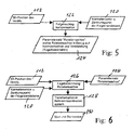
- FIG. 5 shows a schematic flow diagram for the rim impact compensation.
- rim impact compensation in step 122 those previously determined in step 120 (FIG. FIG. 4 ), to obtain a parameter set "rotation axis", that is, the true axis of rotation with respect to the normal vector and the valve position in spherical coordinates is required for carrying out and monitoring the rim deflection compensation, for determining the spread in the course of an impact measurement and for determining the caster change in the caster adjustment
- any rotation of the wheel should be detectable, for which the tracking and measuring of the valve is sufficient.
- the valve is unique on the circumference and can be localized with appropriate accuracy.
- the wheel rotation shall be determined with an accuracy of at least 2 angular minutes. However, no arbitrary rotation of the wheel must be measured.
- the determination of the 3D position of the valve can be performed.
- the measurement and tracking of non-rotationally symmetric edges or structures in the rim can be carried out using appropriate algorithms such as rim rim determination are used.
- FIG. 6 shows a schematic flow chart for calculating the lane and camber angle from the results of step 120 of FIG. 4 and step 124 of FIG. 5 .
- the information about the 3D position of the valve and the information about the normal vector and the center point of the rim edge plane as well as the parameter set "rotation axis" are used in step 126 for determining the position of the rotation axis.
- the result of step 126 is transformed in step 128 into the reference coordinate system of the computer, which then calculates the lane and camber angles in step 130.
- the exemplary embodiment shown is the method variant according to the invention, in which a plurality of rim geometry details are found by the chassis measuring device, and from which the most suitable geometry detail is selected (step 96).
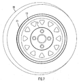
- FIG. 7 the camera image of the side view of the front left wheel rim 36 can be clearly seen, with the measuring camera 42 of the measuring device 24 in step 82 of the method according to FIG FIG. 4 has been recorded.
- This camera image and the following camera images are displayed, for example, on a screen.
- FIG. 8 shows a schematic sectional view of the motor vehicle wheel 36th
- step 88 On the wheel rim 36, three tori can be seen, which are represented by the segmentation in step 88 according to the method of FIG. 4 have been determined, namely the rim flange T1, another torus T2 with a slightly smaller diameter and a much smaller torus T3.
- the verification step 90 gives a positive result, and in step 94 the real contours of these three tori T1, T2 and T3 are determined.
- the verification step 96 gives a negative result, because it is not clear which of the three tori T1, T2 and T3 is now best suited for determining the spatial location of the wheel rim 36 to the meter 24.
- the wheel alignment device determines a plurality of tori, in this case the tori T1, T2 and T3, that one is to be selected for the further method that is best suited for further processing.
- the rim flange torus T1 is selected for further operation by a user or not according to the invention by a computer, not shown, and after re-running the method steps 86, 88, 90, 94 and 96, the spatial position of the wheel rim 36 becomes the measuring device 24 by the following method steps 100, 104, 106, 110, 118,120 determined.
- FIG. 9 shows a camera image of a side view of the motor vehicle wheel 36 with three equidistant points P1, P2 and P3 marked therein.
- the points P1, P2 and P3 are arranged equidistantly on the rim flange torus T1.
- the wheel alignment measuring device Due to poor visibility or contrast conditions in the segmentation according to step 88, the wheel alignment measuring device, for example, has been unable to determine any rim geometry detail, in particular a torus, on the wheel rim 36.
- step 92 for example, a user marks the three equidistant points P1, P2 and P3 on the rim flange torus T1, and the wheel alignment device can re-segment in step 88 because of these three equidistant points P1, P2 and P3 Determine rim flange torus T1 and, based on this, carry out the further procedure for determining the spatial position of the wheel rim to the measuring device, as described in US Pat FIG. 4 is shown.
- FIG. 10 shows a camera image of a side view of the motor vehicle wheel 36 with two circular arc sections b1 and b2 of a rim flange torus T1 recognized therein.
- the two circular arc sections b1 and b2 were detected by the wheel alignment device, but could not be assembled into a complete torus in the segmentation in step 88, since the areas lying between the circular arc sections b1 and b2 could not be detected.
- step 92 for example, by a user using a keyboard or a mouse, the circular arc sections b1 and b2 are identified as lying on a common torus T1 so that the wheel alignment device repeats the rim flange torus T1 in step 88 from the circular arc sections b1 and b2 together or can determine, and this rim flange Torus T1 the further method for determining the spatial position of the wheel rim to the measuring device (steps 104, etc.) can be based.
- FIG. 11 shows a camera image of a side view of the vehicle wheel 36 with a rectangle R marked therein.
- FIG. 11 is the same case as in FIG. 9
- the chassis measuring device was unable to determine any geometry detail, in particular no torus, on the wheel rim 36.
- step 92 a rectangle R will now be around a user's inner T3 torus (see FIG. 7 ), thereby indicating to the wheel alignment device that there is a geometry detail in that area so that the wheel alignment device can more closely examine the area of the R rectangle R of the wheel rim 36 in a subsequent re-segmentation in step 88 and determine the torus T3, and that torus T3 the further method for determining the spatial position of the wheel rim to the measuring device (steps 104, etc.) can be based.
Landscapes
- Physics & Mathematics (AREA)
- General Physics & Mathematics (AREA)
- Length Measuring Devices By Optical Means (AREA)
Claims (19)
- Procédé pour rechercher un détail géométrique d'au moins une jante de roue pour déterminer sa position dans l'espace par rapport à un appareil de mesure, comprenant les étapes suivantes :a) orientation d'au moins une caméra de mesure (32, 34 ; 42, 44) d'un appareil de mesure (14 ; 24) d'un dispositif de mesurage de mécanisme de roulement sur une jante de roue (36) ;b) acquisition d'une image d'une jante de roue (36) par l'au moins une caméra de mesure (32, 34 ; 42, 44) ;c) détermination de plusieurs détails géométriques (T1, T2, T3) dans l'image de la jante de roue ;d) affichage de plusieurs détails géométriques (T1, T2, T3) appropriés pour le procédé sur une image affichée de la jante de roue (36) ;e) sélection d'un détail géométrique (T1) parmi les plusieurs détails géométriques (T1, T2, T3) affichés pour la détermination par un utilisateur de la position dans l'espace de la jante de roue (36) par rapport à l'appareil de mesure (14 ; 24).
- Procédé selon la revendication 1, selon lequel la sélection s'effectue en se basant sur au moins un critère de décision du groupe préférence au rebord de jante, préférence aux détails géométriques de forme torique plutôt qu'en forme de points ou de traits, visibilité et/ou rapport de contraste et diamètre des détails géométriques de forme torique.
- Procédé selon la revendication 1 ou 2,
selon lequel, à l'étape a), au moins une caméra de mesure (32, 34 ; 42, 44) d'un premier appareil de mesure (14 ; 24) est orientée sur une première jante de roue et au moins un caméra de mesure d'un deuxième appareil de mesure (18 ; 28) est orientée sur une deuxième jante de roue ; et
selon lequel, à l'étape b), au moins une image de chaque jante de roue est acquise respectivement par les caméras de mesure. - Procédé selon la revendication 3,
selon lequel, à l'étape a), au moins une caméra de mesure d'un premier appareil de mesure est orientée sur une première jante de roue, au moins un caméra de mesure d'un deuxième appareil de mesure est orientée sur une deuxième jante de roue, au moins un caméra de mesure d'un troisième appareil de mesure est orientée sur une troisième jante de roue et au moins un caméra de mesure d'un quatrième appareil de mesure est orientée sur une quatrième jante de roue ; et
selon lequel, à l'étape b), au moins une image de chaque jante de roue est acquise respectivement par les caméras de mesure. - Procédé selon la revendication 3 ou 4, selon lequel, après avoir effectué la sélection d'un détail géométrique déterminé, le détail géométrique est soumis à un contrôle pour vérifier s'il existe également dans les images de caméra de mesure des autres appareils de mesure.
- Procédé selon la revendication 2 ou 3, selon lequel, à l'étape c), au moins un détail géométrique qui apparaît dans toutes les images des jantes de roue est déterminé ; et
selon lequel, à l'étape d), un détail géométrique déterminé est sélectionné pour la détermination de la position dans l'espace des jantes de roue par rapport aux appareils de mesure. - Procédé selon l'une des revendications 1 à 6, selon lequel deux caméras de mesure stéréoscopiques (32, 34 ; 42, 44) sont orientées selon un angle donné sur une jante de roue (36).
- Procédé selon l'une des revendications 1 à 7, selon lequel l'image de la jante de roue (36) ou les images de la jante de roue (36) et/ou les plusieurs détails géométriques déterminés sont représentés sur un appareil d'affichage.
- Procédé selon l'une des revendications 1 à 8, selon lequel la sélection d'un détail géométrique déterminé (T1, T2, T3) dans l'image de la jante de roue (36) s'effectue par le biais d'un appareil d'affichage et/ou par le biais d'un appareil de saisie.
- Procédé selon l'une des revendications 1 à 8, selon lequel la sélection d'un détail géométrique déterminé (T1, T2, T3) dans l'image de la jante de roue (36) s'effectue au moyen d'un ou de plusieurs critères d'évaluation.
- Procédé selon l'une des revendications 1 à 10, selon lequel le dispositif de mesurage de mécanisme de roulement évalue les plusieurs détails géométriques déterminés dans l'image de la jante de roue (36).
- Procédé selon la revendication 11, selon lequel l'évaluation des plusieurs détails géométriques est également affichée sur l'appareil d'affichage.
- Procédé selon l'une des revendications précédentes, selon lequel au moins un détail géométrique est un tore (T1, T2, T3), notamment un tore autour du bord de jante (T1).
- Procédé selon l'une des revendications précédentes, selon lequel les paramètres du détail géométrique sélectionné ou déterminé sont mis en mémoire.
- Procédé pour déterminer la position dans l'espace d'une jante de roue par rapport à un appareil de mesure, lequel présente au moins une caméra, la jante de roue se trouvant dans le champ de vision de la caméra, comprenant les étapes suivantes :- mise à disposition d'un modèle qui décrit par des paramètres de modèle un modèle physique d'un détail géométrique (T1, T2, T3) localisable ainsi que la position dans l'espace du modèle physique par rapport à l'appareil de mesure,- acquisition d'une image de la jante de roue (36) avec la caméra (32, 34 ; 42, 44) et recherche d'un détail géométrique (T1, T2, T3) d'au moins une jante de roue (36) conformément à un procédé selon l'une des revendications 1 à 14,- adaptation de la représentation du modèle physique résultant des paramètres de modèle à l'image du détail géométrique (T1, T2, T3) en modifiant des paramètres de modèle du modèle, et- suivi des modifications des paramètres de modèle du modèle lors de l'adaptation,- procédé selon lequel les données en rapport avec la position du modèle physique du détail géométrique (T1, T2, T3) restituent la position dans l'espace du détail géométrique (T1, T2, T3) et ainsi de la jante de roue (36) elle-même, si la représentation du modèle physique du détail géométrique qui résulte des paramètres de modèle coïncide avec l'image acquise du détail géométrique (T1, T2, T3) dans des limites de tolérance prédéfinies.
- Procédé de mesurage de mécanisme de roulement sur des véhicules automobiles,- selon lequel le procédé selon la revendication 15 est mis en oeuvre sur les jantes de roue (36) du véhicule automobile (12),- selon lequel les positions relatives des appareils de mesure sont déterminées pour la réalisation des mesures, les résultats de mesure des mesures sur les roues (36) du véhicule automobile (12) étant convertis en valeurs de position de roue en tenant compte des positions relatives des appareils de mesure et les valeurs de position de roue étant diffusées ou affichées.
- Appareil de mesure pour déterminer la position dans l'espace d'une jante de roue par rapport à l'appareil de mesure, l'appareil de mesure (14 ; 24) présentant au moins une caméra (32, 42 ; 34, 44), la jante de roue (36) se trouvant dans le champ de vision de la caméra (32, 42 ; 34, 44), caractérisé par un ordinateur qui est programmé pour mettre en oeuvre le procédé selon la revendication 15.
- Dispositif de mesurage du mécanisme de roulement pour véhicules automobiles,- comprenant au moins deux appareils de mesure selon la revendication 17, lesquels sont positionnés sur un poste de mesure (10, 20) de telle sorte qu'un appareil de mesure est à chaque fois associé à l'une des roues (36) d'un véhicule automobile (12),- les positions relatives des appareils de mesure étant déterminées lors de la réalisation des mesures,- comprenant un ordinateur qui convertit les résultats de mesure des mesures sur les roues (36) du véhicule automobile (12) en valeurs de position de roue en tenant compte des positions relatives des appareils de mesure, et- comprenant un dispositif d'affichage/de diffusion qui diffuse ou affiche les valeurs de position de roue.
- Piste d'essai pour véhicules automobiles,- comprenant au moins deux appareils de mesure selon la revendication 17, lesquels sont positionnés de telle sorte qu'un appareil de mesure est à chaque fois associé à l'une des roues (36) d'un véhicule automobile (12),- les positions relatives des appareils de mesure étant déterminées lors de la réalisation des mesures,- comprenant un ordinateur qui convertit les résultats de mesure des mesures sur les roues (36) du véhicule automobile (12) en valeurs de position de roue en tenant compte des positions relatives des appareils de mesure, et- comprenant un dispositif d'affichage/de diffusion qui diffuse ou affiche les valeurs de position de roue.
Applications Claiming Priority (2)
| Application Number | Priority Date | Filing Date | Title |
|---|---|---|---|
| DE102006042308A DE102006042308A1 (de) | 2006-09-08 | 2006-09-08 | Verfahren zum Auffinden eines Geometriedetails zur Bestimmung der räumlichen Lage einer Radfelge zu einem Messgerät sowie Verfahren und Vorrichtung zur Bestimmung der räumlichen Lage einer Radfelge zu einem Messgerät |
| PCT/EP2007/058853 WO2008028831A1 (fr) | 2006-09-08 | 2007-08-27 | ProcÉDÉ de dÉtection d'un dÉtail gÉOMÉtrique pour dÉfinir la position dans l'espace d'une jante de roue par rapport À un appareil de mesure ainsi que procÉDÉ et dispositif pour dÉfinir la position dans l'espace d'une jante de roue par rapport À un apparei |
Publications (2)
| Publication Number | Publication Date |
|---|---|
| EP2064517A1 EP2064517A1 (fr) | 2009-06-03 |
| EP2064517B1 true EP2064517B1 (fr) | 2013-02-27 |
Family
ID=38846836
Family Applications (1)
| Application Number | Title | Priority Date | Filing Date |
|---|---|---|---|
| EP07802894A Not-in-force EP2064517B1 (fr) | 2006-09-08 | 2007-08-27 | Prodede de detection d'un detail geometrique pour definir la position dans l'espace d'une jante de roue par rapport a un appareil de mesure ainsi que procede et dispositif pour definir la position dans l'espace d'une jante de roue par rapport a un appareil |
Country Status (4)
| Country | Link |
|---|---|
| US (1) | US7877883B2 (fr) |
| EP (1) | EP2064517B1 (fr) |
| DE (1) | DE102006042308A1 (fr) |
| WO (1) | WO2008028831A1 (fr) |
Families Citing this family (15)
| Publication number | Priority date | Publication date | Assignee | Title |
|---|---|---|---|---|
| US7444752B2 (en) * | 2005-09-28 | 2008-11-04 | Hunter Engineering Company | Method and apparatus for vehicle service system optical target |
| DE102005063051A1 (de) * | 2005-12-29 | 2007-07-05 | Robert Bosch Gmbh | Verfahren zur optischen Fahrwerksvermessung |
| DE102006041822A1 (de) * | 2006-09-06 | 2008-03-27 | Beissbarth Gmbh | Verfahren zur Fahrwerksmessung eines Kraftfahrzeugs, Fahrwerksvermessungseinrichtung sowie Kraftfahrzeugprüfstrasse |
| DE102006041821A1 (de) * | 2006-09-06 | 2008-03-27 | Beissbarth Gmbh | Verfahren zur relativen Positionierung eines Messgegenstands und eines Kraftfahrzeugs zu einem Messgerät sowie Messgerät und Fahrwerksvermessungseinrichtung |
| US7953247B2 (en) | 2007-05-21 | 2011-05-31 | Snap-On Incorporated | Method and apparatus for wheel alignment |
| US8650766B2 (en) * | 2008-09-12 | 2014-02-18 | Robert Bosch Gmbh | Target system, set of target systems and device for optically aligning an axle |
| IT1399988B1 (it) * | 2010-05-05 | 2013-05-09 | Space S R L Con Unico Socio | Sistema, e relativo metodo, di determinazione dell'allineamento delle ruote di un veicolo |
| CN102042806B (zh) * | 2010-10-25 | 2012-03-28 | 吉林大学 | 基于机器视觉的汽车车轮平面及轮辋的空间位置检测系统 |
| US9785610B1 (en) * | 2011-11-15 | 2017-10-10 | Hunter Engineering Company | Visual display of vehicle wheel assembly for vehicle wheel service system |
| ITMI20121129A1 (it) * | 2012-06-27 | 2013-12-28 | Vamag Srl | Sistema e metodo di misura degli angoli di assetto delle ruote di un autoveicolo, per mezzo di bersagli tridimensionali. |
| WO2014151666A1 (fr) | 2013-03-15 | 2014-09-25 | Hunter Engineering Company | Procédé de détermination de paramètres d'un objet en rotation dans un motif projeté |
| AT512762B1 (de) * | 2013-08-01 | 2015-01-15 | Avl List Gmbh | Verfahren und Anordnung zur Fahrdynamikbewertung |
| DE102013219462A1 (de) * | 2013-09-26 | 2015-03-26 | Robert Bosch Gmbh | Fahrwerksvermessung bei Umgebungslicht |
| CZ310576B6 (cs) * | 2020-03-02 | 2025-12-24 | TRIFID AUTOMATION s.r.o. | Způsob bezkontaktního měření geometrických vlastností objektů a zařízení k provádění tohoto způsobu |
| DE102022201709A1 (de) | 2022-02-18 | 2023-01-19 | Zf Friedrichshafen Ag | Verfahren zum Anzeigen einer Position eines Reifenventils eines Fahrzeugreifens |
Family Cites Families (16)
| Publication number | Priority date | Publication date | Assignee | Title |
|---|---|---|---|---|
| US5488472A (en) * | 1995-01-10 | 1996-01-30 | Hunter Engineering Company | Apparatus for determining vehicle wheel alignment positions and orientations |
| IT1294940B1 (it) * | 1997-08-01 | 1999-04-23 | Corghi Spa | Metodo e dispositivo per regolare l'assetto di un autoveicolo |
| US6323776B1 (en) | 1999-12-21 | 2001-11-27 | Snap-On Technologies, Inc. | Method and apparatus of automatically identifying faults in a machine vision measuring system |
| EP1277027B1 (fr) * | 2000-04-25 | 2009-07-22 | Snap-on Incorporated | Mesure de l'alignement des roues et des essieux de vehicules a moteur |
| DE10033366B4 (de) * | 2000-07-08 | 2007-10-04 | Festo Ag & Co. | Verfahren und Erfassungsvorrichtung zur Erfassung von Parametern an maschinellen Einrichtungen |
| JP2004530889A (ja) * | 2001-06-15 | 2004-10-07 | スナップ − オン テクノロジーズ,インコーポレイテッド | 自動較正位置決定システム |
| US20030055535A1 (en) * | 2001-09-17 | 2003-03-20 | Hunter Engineering Company | Voice interface for vehicle wheel alignment system |
| DE60234308D1 (de) * | 2002-02-04 | 2009-12-24 | Corghi Spa | Vorrichtung zur Messung der charakteristischen Lageparameter eines Kraftfahrzeuges |
| US6871409B2 (en) * | 2002-12-18 | 2005-03-29 | Snap-On Incorporated | Gradient calculating camera board |
| DE102004013441A1 (de) | 2004-03-18 | 2005-10-13 | Beissbarth Gmbh | Meßverfahren und Meßgerät zur Bestimmung der räumlichen Lage einer Radfelge sowie Fahrwerkvermessungseinrichtung |
| US20060152711A1 (en) * | 2004-12-30 | 2006-07-13 | Dale James L Jr | Non-contact vehicle measurement method and system |
| US7369222B2 (en) * | 2005-05-13 | 2008-05-06 | Snap-On Technologies, Inc. | Wheel aligner measurement module attachment system |
| DE102005022565A1 (de) * | 2005-05-17 | 2006-11-23 | Beissbarth Gmbh | Automatisches Belichtungssystem für ein berührungslos messendes Automobilservicegerät |
| US7313869B1 (en) * | 2006-07-18 | 2008-01-01 | Snap-On Incorporated | Vehicle wheel alignment system and methodology |
| US7953247B2 (en) * | 2007-05-21 | 2011-05-31 | Snap-On Incorporated | Method and apparatus for wheel alignment |
| US7684026B2 (en) * | 2007-07-27 | 2010-03-23 | Snap-On Incorporated | Fault tolerant wheel alignment head and system |
-
2006
- 2006-09-08 DE DE102006042308A patent/DE102006042308A1/de not_active Withdrawn
-
2007
- 2007-08-27 WO PCT/EP2007/058853 patent/WO2008028831A1/fr not_active Ceased
- 2007-08-27 EP EP07802894A patent/EP2064517B1/fr not_active Not-in-force
- 2007-08-27 US US12/304,165 patent/US7877883B2/en not_active Expired - Fee Related
Also Published As
| Publication number | Publication date |
|---|---|
| DE102006042308A1 (de) | 2008-03-27 |
| US20100037473A1 (en) | 2010-02-18 |
| WO2008028831A1 (fr) | 2008-03-13 |
| EP2064517A1 (fr) | 2009-06-03 |
| US7877883B2 (en) | 2011-02-01 |
Similar Documents
| Publication | Publication Date | Title |
|---|---|---|
| EP2064517B1 (fr) | Prodede de detection d'un detail geometrique pour definir la position dans l'espace d'une jante de roue par rapport a un appareil de mesure ainsi que procede et dispositif pour definir la position dans l'espace d'une jante de roue par rapport a un appareil | |
| EP1725834B1 (fr) | Procede et dispositif de mesure pour determiner la position spatiale d'une jante de roue et dispositif de mesure du chassis | |
| DE69330466T2 (de) | Verfahren und vorrichtung zur bestimmung der ausrichtung von kraftfahrzeugrädern | |
| DE69721022T2 (de) | Kalibrierung von kameras bei anwendung in radjustierung | |
| DE69636925T2 (de) | Verfahren und vorrichtung zur feststellung der ausrichtung von kraftfahrzeugrädern | |
| EP3645359B1 (fr) | Procédé et dispositif de détermination d'un désalignement d'un disque de frein | |
| EP2914205B1 (fr) | Dispositif d'étalonnage et procédé d'étalonnage d'une caméra dentaire | |
| EP2069714B1 (fr) | Procede pour la mesure du train de roulement d`un vehicule automobile, dispositif de mesure du train de roulement ainsi que voie de controle | |
| EP1969310B1 (fr) | Procédé de mesure optique de châssis | |
| EP2247919B1 (fr) | Procédé et dispositif de contrôle du référencement de têtes de mesure d'un système de mesure pour l'alignement de châssis | |
| EP1505367A2 (fr) | Méthode d'évaluation de la géometrie des essieux et capteur pour l'implémentation de ladite méthode | |
| WO1999034166A1 (fr) | Dispositif de determination de la geometrie de roues et/ou d'essieux de vehicules a moteur | |
| WO2011104041A1 (fr) | Procédé et dispositif pour déterminer des distances sur un véhicule | |
| DE102022104880B4 (de) | Verfahren zur Kalibrierung eines portablen Referenzsensorsystems, portables Referenzsensorsystem und Verwendung des portablen Referenzsensorsystems | |
| DE102005063083A1 (de) | Verfahren zur optischen Fahrwerksvermessung | |
| EP2064518A1 (fr) | Procédé pour la détermination des distances en vue de la mesure du train de roulement d'un véhicule automobile, ainsi qu'instrument de mesure, dispositif de mesure du train de roulement et voie de contrôle | |
| DE102008000837A1 (de) | Fahrwerksvermessungssystem sowie Verfahren zum Bestimmen der Lageparameter von Messköpfen eines Fahrwerksvermessungssystems | |
| EP3545259A1 (fr) | Procédé et dispositif d'analyse d'objets de test à symétrie de révolution | |
| DE102009035840A1 (de) | Verfahren zum Positionieren und/oder Einstellen von Hochgeschwindigkeitskameras | |
| DE102019131863A1 (de) | Verwendung einer Vorrichtung zur photogrammetrischen Vermessung von Objekten zur Bestimmung von Position und/oder Orientierung von Teilen eines Fahrzeugs | |
| EP2055255A1 (fr) | Vérification de l'état de calibrage d'un système de détection optique | |
| DE60115013T2 (de) | Messung der ausrichtung von fahrzeugrädern mit videokameras und wiederholten näherungsrechnungen | |
| DE102020212142A1 (de) | Verfahren zur Kalibrierung eines Kalibrationssensors, Steuergerät und Verwendung des Steuergeräts | |
| DE102008046104A1 (de) | Vorrichtung und Verfahren zur Spurvermessung von Fahrzeugen | |
| WO2007077063A1 (fr) | Procede et dispositif de mesure sans contact de la geometrie d'un essieu |
Legal Events
| Date | Code | Title | Description |
|---|---|---|---|
| PUAI | Public reference made under article 153(3) epc to a published international application that has entered the european phase |
Free format text: ORIGINAL CODE: 0009012 |
|
| 17P | Request for examination filed |
Effective date: 20090408 |
|
| AK | Designated contracting states |
Kind code of ref document: A1 Designated state(s): AT BE BG CH CY CZ DE DK EE ES FI FR GB GR HU IE IS IT LI LT LU LV MC MT NL PL PT RO SE SI SK TR |
|
| AX | Request for extension of the european patent |
Extension state: AL BA HR MK RS |
|
| 17Q | First examination report despatched |
Effective date: 20100317 |
|
| DAX | Request for extension of the european patent (deleted) | ||
| GRAP | Despatch of communication of intention to grant a patent |
Free format text: ORIGINAL CODE: EPIDOSNIGR1 |
|
| GRAS | Grant fee paid |
Free format text: ORIGINAL CODE: EPIDOSNIGR3 |
|
| GRAA | (expected) grant |
Free format text: ORIGINAL CODE: 0009210 |
|
| AK | Designated contracting states |
Kind code of ref document: B1 Designated state(s): AT BE BG CH CY CZ DE DK EE ES FI FR GB GR HU IE IS IT LI LT LU LV MC MT NL PL PT RO SE SI SK TR |
|
| REG | Reference to a national code |
Ref country code: GB Ref legal event code: FG4D Free format text: NOT ENGLISH |
|
| REG | Reference to a national code |
Ref country code: CH Ref legal event code: EP |
|
| REG | Reference to a national code |
Ref country code: AT Ref legal event code: REF Ref document number: 598728 Country of ref document: AT Kind code of ref document: T Effective date: 20130315 |
|
| REG | Reference to a national code |
Ref country code: IE Ref legal event code: FG4D Free format text: LANGUAGE OF EP DOCUMENT: GERMAN |
|
| REG | Reference to a national code |
Ref country code: DE Ref legal event code: R096 Ref document number: 502007011375 Country of ref document: DE Effective date: 20130425 |
|
| REG | Reference to a national code |
Ref country code: LT Ref legal event code: MG4D |
|
| PG25 | Lapsed in a contracting state [announced via postgrant information from national office to epo] |
Ref country code: BG Free format text: LAPSE BECAUSE OF FAILURE TO SUBMIT A TRANSLATION OF THE DESCRIPTION OR TO PAY THE FEE WITHIN THE PRESCRIBED TIME-LIMIT Effective date: 20130527 Ref country code: IS Free format text: LAPSE BECAUSE OF FAILURE TO SUBMIT A TRANSLATION OF THE DESCRIPTION OR TO PAY THE FEE WITHIN THE PRESCRIBED TIME-LIMIT Effective date: 20130627 Ref country code: ES Free format text: LAPSE BECAUSE OF FAILURE TO SUBMIT A TRANSLATION OF THE DESCRIPTION OR TO PAY THE FEE WITHIN THE PRESCRIBED TIME-LIMIT Effective date: 20130607 Ref country code: SE Free format text: LAPSE BECAUSE OF FAILURE TO SUBMIT A TRANSLATION OF THE DESCRIPTION OR TO PAY THE FEE WITHIN THE PRESCRIBED TIME-LIMIT Effective date: 20130227 Ref country code: LT Free format text: LAPSE BECAUSE OF FAILURE TO SUBMIT A TRANSLATION OF THE DESCRIPTION OR TO PAY THE FEE WITHIN THE PRESCRIBED TIME-LIMIT Effective date: 20130227 |
|
| REG | Reference to a national code |
Ref country code: NL Ref legal event code: VDEP Effective date: 20130227 |
|
| PG25 | Lapsed in a contracting state [announced via postgrant information from national office to epo] |
Ref country code: SI Free format text: LAPSE BECAUSE OF FAILURE TO SUBMIT A TRANSLATION OF THE DESCRIPTION OR TO PAY THE FEE WITHIN THE PRESCRIBED TIME-LIMIT Effective date: 20130227 Ref country code: GR Free format text: LAPSE BECAUSE OF FAILURE TO SUBMIT A TRANSLATION OF THE DESCRIPTION OR TO PAY THE FEE WITHIN THE PRESCRIBED TIME-LIMIT Effective date: 20130528 Ref country code: FI Free format text: LAPSE BECAUSE OF FAILURE TO SUBMIT A TRANSLATION OF THE DESCRIPTION OR TO PAY THE FEE WITHIN THE PRESCRIBED TIME-LIMIT Effective date: 20130227 Ref country code: PL Free format text: LAPSE BECAUSE OF FAILURE TO SUBMIT A TRANSLATION OF THE DESCRIPTION OR TO PAY THE FEE WITHIN THE PRESCRIBED TIME-LIMIT Effective date: 20130227 Ref country code: PT Free format text: LAPSE BECAUSE OF FAILURE TO SUBMIT A TRANSLATION OF THE DESCRIPTION OR TO PAY THE FEE WITHIN THE PRESCRIBED TIME-LIMIT Effective date: 20130627 Ref country code: LV Free format text: LAPSE BECAUSE OF FAILURE TO SUBMIT A TRANSLATION OF THE DESCRIPTION OR TO PAY THE FEE WITHIN THE PRESCRIBED TIME-LIMIT Effective date: 20130227 |
|
| PG25 | Lapsed in a contracting state [announced via postgrant information from national office to epo] |
Ref country code: RO Free format text: LAPSE BECAUSE OF FAILURE TO SUBMIT A TRANSLATION OF THE DESCRIPTION OR TO PAY THE FEE WITHIN THE PRESCRIBED TIME-LIMIT Effective date: 20130227 Ref country code: SK Free format text: LAPSE BECAUSE OF FAILURE TO SUBMIT A TRANSLATION OF THE DESCRIPTION OR TO PAY THE FEE WITHIN THE PRESCRIBED TIME-LIMIT Effective date: 20130227 Ref country code: CZ Free format text: LAPSE BECAUSE OF FAILURE TO SUBMIT A TRANSLATION OF THE DESCRIPTION OR TO PAY THE FEE WITHIN THE PRESCRIBED TIME-LIMIT Effective date: 20130227 Ref country code: NL Free format text: LAPSE BECAUSE OF FAILURE TO SUBMIT A TRANSLATION OF THE DESCRIPTION OR TO PAY THE FEE WITHIN THE PRESCRIBED TIME-LIMIT Effective date: 20130227 Ref country code: DK Free format text: LAPSE BECAUSE OF FAILURE TO SUBMIT A TRANSLATION OF THE DESCRIPTION OR TO PAY THE FEE WITHIN THE PRESCRIBED TIME-LIMIT Effective date: 20130227 Ref country code: EE Free format text: LAPSE BECAUSE OF FAILURE TO SUBMIT A TRANSLATION OF THE DESCRIPTION OR TO PAY THE FEE WITHIN THE PRESCRIBED TIME-LIMIT Effective date: 20130227 |
|
| PG25 | Lapsed in a contracting state [announced via postgrant information from national office to epo] |
Ref country code: CY Free format text: LAPSE BECAUSE OF FAILURE TO SUBMIT A TRANSLATION OF THE DESCRIPTION OR TO PAY THE FEE WITHIN THE PRESCRIBED TIME-LIMIT Effective date: 20130227 |
|
| PG25 | Lapsed in a contracting state [announced via postgrant information from national office to epo] |
Ref country code: IT Free format text: LAPSE BECAUSE OF FAILURE TO SUBMIT A TRANSLATION OF THE DESCRIPTION OR TO PAY THE FEE WITHIN THE PRESCRIBED TIME-LIMIT Effective date: 20130227 |
|
| PLBE | No opposition filed within time limit |
Free format text: ORIGINAL CODE: 0009261 |
|
| STAA | Information on the status of an ep patent application or granted ep patent |
Free format text: STATUS: NO OPPOSITION FILED WITHIN TIME LIMIT |
|
| 26N | No opposition filed |
Effective date: 20131128 |
|
| BERE | Be: lapsed |
Owner name: ROBERT BOSCH G.M.B.H. Effective date: 20130831 |
|
| REG | Reference to a national code |
Ref country code: DE Ref legal event code: R097 Ref document number: 502007011375 Country of ref document: DE Effective date: 20131128 |
|
| REG | Reference to a national code |
Ref country code: CH Ref legal event code: PL |
|
| GBPC | Gb: european patent ceased through non-payment of renewal fee |
Effective date: 20130827 |
|
| PG25 | Lapsed in a contracting state [announced via postgrant information from national office to epo] |
Ref country code: MC Free format text: LAPSE BECAUSE OF FAILURE TO SUBMIT A TRANSLATION OF THE DESCRIPTION OR TO PAY THE FEE WITHIN THE PRESCRIBED TIME-LIMIT Effective date: 20130227 Ref country code: CH Free format text: LAPSE BECAUSE OF NON-PAYMENT OF DUE FEES Effective date: 20130831 Ref country code: LI Free format text: LAPSE BECAUSE OF NON-PAYMENT OF DUE FEES Effective date: 20130831 |
|
| REG | Reference to a national code |
Ref country code: IE Ref legal event code: MM4A |
|
| PG25 | Lapsed in a contracting state [announced via postgrant information from national office to epo] |
Ref country code: BE Free format text: LAPSE BECAUSE OF NON-PAYMENT OF DUE FEES Effective date: 20130831 |
|
| PG25 | Lapsed in a contracting state [announced via postgrant information from national office to epo] |
Ref country code: GB Free format text: LAPSE BECAUSE OF NON-PAYMENT OF DUE FEES Effective date: 20130827 Ref country code: IE Free format text: LAPSE BECAUSE OF NON-PAYMENT OF DUE FEES Effective date: 20130827 |
|
| REG | Reference to a national code |
Ref country code: AT Ref legal event code: MM01 Ref document number: 598728 Country of ref document: AT Kind code of ref document: T Effective date: 20130827 |
|
| PG25 | Lapsed in a contracting state [announced via postgrant information from national office to epo] |
Ref country code: AT Free format text: LAPSE BECAUSE OF NON-PAYMENT OF DUE FEES Effective date: 20130827 |
|
| PG25 | Lapsed in a contracting state [announced via postgrant information from national office to epo] |
Ref country code: MT Free format text: LAPSE BECAUSE OF FAILURE TO SUBMIT A TRANSLATION OF THE DESCRIPTION OR TO PAY THE FEE WITHIN THE PRESCRIBED TIME-LIMIT Effective date: 20130227 Ref country code: TR Free format text: LAPSE BECAUSE OF FAILURE TO SUBMIT A TRANSLATION OF THE DESCRIPTION OR TO PAY THE FEE WITHIN THE PRESCRIBED TIME-LIMIT Effective date: 20130227 |
|
| PG25 | Lapsed in a contracting state [announced via postgrant information from national office to epo] |
Ref country code: LU Free format text: LAPSE BECAUSE OF NON-PAYMENT OF DUE FEES Effective date: 20130827 Ref country code: HU Free format text: LAPSE BECAUSE OF FAILURE TO SUBMIT A TRANSLATION OF THE DESCRIPTION OR TO PAY THE FEE WITHIN THE PRESCRIBED TIME-LIMIT; INVALID AB INITIO Effective date: 20070827 |
|
| REG | Reference to a national code |
Ref country code: FR Ref legal event code: PLFP Year of fee payment: 10 |
|
| REG | Reference to a national code |
Ref country code: FR Ref legal event code: PLFP Year of fee payment: 11 |
|
| REG | Reference to a national code |
Ref country code: FR Ref legal event code: PLFP Year of fee payment: 12 |
|
| REG | Reference to a national code |
Ref country code: DE Ref legal event code: R082 Ref document number: 502007011375 Country of ref document: DE Representative=s name: SCHMITT-NILSON SCHRAUD WAIBEL WOHLFROM PATENTA, DE Ref country code: DE Ref legal event code: R081 Ref document number: 502007011375 Country of ref document: DE Owner name: BEISSBARTH GMBH, DE Free format text: FORMER OWNER: ROBERT BOSCH GMBH, 70469 STUTTGART, DE |
|
| PGFP | Annual fee paid to national office [announced via postgrant information from national office to epo] |
Ref country code: FR Payment date: 20200820 Year of fee payment: 14 |
|
| PGFP | Annual fee paid to national office [announced via postgrant information from national office to epo] |
Ref country code: DE Payment date: 20201027 Year of fee payment: 14 |
|
| REG | Reference to a national code |
Ref country code: DE Ref legal event code: R119 Ref document number: 502007011375 Country of ref document: DE |
|
| PG25 | Lapsed in a contracting state [announced via postgrant information from national office to epo] |
Ref country code: FR Free format text: LAPSE BECAUSE OF NON-PAYMENT OF DUE FEES Effective date: 20210831 Ref country code: DE Free format text: LAPSE BECAUSE OF NON-PAYMENT OF DUE FEES Effective date: 20220301 |