EP2064724B1 - Hilfsauslöser für einen leistungsschalter - Google Patents
Hilfsauslöser für einen leistungsschalter Download PDFInfo
- Publication number
- EP2064724B1 EP2064724B1 EP06805336.2A EP06805336A EP2064724B1 EP 2064724 B1 EP2064724 B1 EP 2064724B1 EP 06805336 A EP06805336 A EP 06805336A EP 2064724 B1 EP2064724 B1 EP 2064724B1
- Authority
- EP
- European Patent Office
- Prior art keywords
- release
- circuit
- voltage
- auxiliary
- undervoltage
- Prior art date
- Legal status (The legal status is an assumption and is not a legal conclusion. Google has not performed a legal analysis and makes no representation as to the accuracy of the status listed.)
- Not-in-force
Links
- 239000004065 semiconductor Substances 0.000 claims description 4
- 238000004519 manufacturing process Methods 0.000 description 3
- 230000001960 triggered effect Effects 0.000 description 3
- 101000581533 Homo sapiens Methylcrotonoyl-CoA carboxylase beta chain, mitochondrial Proteins 0.000 description 1
- 102100027320 Methylcrotonoyl-CoA carboxylase beta chain, mitochondrial Human genes 0.000 description 1
- 230000005540 biological transmission Effects 0.000 description 1
- 238000010276 construction Methods 0.000 description 1
- 230000008878 coupling Effects 0.000 description 1
- 238000010168 coupling process Methods 0.000 description 1
- 238000005859 coupling reaction Methods 0.000 description 1
- 238000005265 energy consumption Methods 0.000 description 1
- 238000009434 installation Methods 0.000 description 1
- 230000010354 integration Effects 0.000 description 1
- 238000002955 isolation Methods 0.000 description 1
- 239000000463 material Substances 0.000 description 1
Images
Classifications
-
- H—ELECTRICITY
- H01—ELECTRIC ELEMENTS
- H01H—ELECTRIC SWITCHES; RELAYS; SELECTORS; EMERGENCY PROTECTIVE DEVICES
- H01H83/00—Protective switches, e.g. circuit-breaking switches, or protective relays operated by abnormal electrical conditions otherwise than solely by excess current
- H01H83/10—Protective switches, e.g. circuit-breaking switches, or protective relays operated by abnormal electrical conditions otherwise than solely by excess current operated by excess voltage, e.g. for lightning protection
-
- H—ELECTRICITY
- H01—ELECTRIC ELEMENTS
- H01H—ELECTRIC SWITCHES; RELAYS; SELECTORS; EMERGENCY PROTECTIVE DEVICES
- H01H83/00—Protective switches, e.g. circuit-breaking switches, or protective relays operated by abnormal electrical conditions otherwise than solely by excess current
- H01H83/12—Protective switches, e.g. circuit-breaking switches, or protective relays operated by abnormal electrical conditions otherwise than solely by excess current operated by voltage falling below a predetermined value, e.g. for no-volt protection
-
- H—ELECTRICITY
- H01—ELECTRIC ELEMENTS
- H01H—ELECTRIC SWITCHES; RELAYS; SELECTORS; EMERGENCY PROTECTIVE DEVICES
- H01H71/00—Details of the protective switches or relays covered by groups H01H73/00 - H01H83/00
- H01H71/02—Housings; Casings; Bases; Mountings
- H01H71/0264—Mountings or coverplates for complete assembled circuit breakers, e.g. snap mounting in panel
- H01H71/0271—Mounting several complete assembled circuit breakers together
- H01H2071/0278—Mounting several complete assembled circuit breakers together with at least one of juxtaposed casings dedicated to an auxiliary device, e.g. for undervoltage or shunt trip
-
- H—ELECTRICITY
- H01—ELECTRIC ELEMENTS
- H01H—ELECTRIC SWITCHES; RELAYS; SELECTORS; EMERGENCY PROTECTIVE DEVICES
- H01H83/00—Protective switches, e.g. circuit-breaking switches, or protective relays operated by abnormal electrical conditions otherwise than solely by excess current
- H01H83/20—Protective switches, e.g. circuit-breaking switches, or protective relays operated by abnormal electrical conditions otherwise than solely by excess current operated by excess current as well as by some other abnormal electrical condition
- H01H2083/203—Protective switches, e.g. circuit-breaking switches, or protective relays operated by abnormal electrical conditions otherwise than solely by excess current operated by excess current as well as by some other abnormal electrical condition with shunt trip circuits, e.g. NC contact in an undervoltage coil circuit
Definitions
- the invention relates to an auxiliary release for a circuit breaker.
- the auxiliary release can be used, for example, as an accessory for a low-voltage molded case circuit breaker.
- circuit breakers There is a requirement for modern circuit breakers to provide the functions of a voltage release and an undervoltage release in a device, e.g. in a low-voltage molded case circuit breaker.
- An undervoltage release switches off when no or a voltage below a defined value is applied to it. Thereby, e.g. uncontrolled machine restart after power failure is prevented.
- a voltage release switches off if it has a voltage exceeding a certain value.
- the equipped with undervoltage release and voltage release circuit breaker should preferably have an extremely compact design.
- the envelope dimensions of individual circuit breaker types have already been defined, and additional auxiliary and alarm switches must be integrated into such circuit breakers.
- EP-A-1 122 758 known.
- the invention is therefore an object of the invention to provide an auxiliary release available that offers the possibility with simple and inexpensive construction, the function of an undervoltage release and the function of a voltage release with low energy consumption and high tripping reliability in a device with small envelopes to unite.
- auxiliary release for a circuit breaker, wherein the auxiliary release comprises an undervoltage release for the mechanical actuation of an actuating element and in the circuit of the undervoltage release a connection point for connection of a voltage release is arranged.
- the undervoltage release on a coil which exerts a force on an actuating element in the current-carrying state.
- the circuit in which the voltage release is integrable so is the circuit in which the coil of the undervoltage release is arranged.
- the movement of the actuating element on or in the coil is mechanically transmitted to the actuating element.
- the actuator is eg a mechanical switch lock of a circuit breaker which triggers or switches the circuit breaker, that brings the contacts of the circuit breaker in the open position.
- auxiliary release in the circuit of the undervoltage release results in a flexibility of the auxiliary release in that it can be used in one embodiment without a voltage release and in another embodiment with an integrated voltage release.
- the auxiliary release according to the invention can, if necessary, be retrofitted with a voltage release.
- the auxiliary release further comprises a voltage release, which is connected to the connection point in the circuit of the undervoltage release and which causes an interruption of the circuit when a certain voltage applied to it is exceeded.
- a voltage release and an undervoltage release are combined in an accessory for a circuit breaker.
- the voltage release is actuated by an external current pulse.
- the voltage release and the undervoltage release define different, independent control voltage ranges in which the circuit breaker should remain closed or be triggered / switched off.
- a volume saving in the interior of the circuit breaker is achieved in that only one module, in which the functions of the voltage release and the undervoltage release are combined, is used.
- the simple production possibility of the module fulfilling both functions saves manufacturing costs.
- the reliability of the circuit increases, since only an interface between the auxiliary release and mechanical release shaft of the actuator exists.
- auxiliary release is not limited to low-voltage molded circuit breaker MCCB, but it can also be used in circuit breakers of different size and power such as open circuit breakers ACB (air circuit breaker).
- the voltage release in the circuit of the undervoltage release is provided that the voltage release is permanently connected to the connection point in the circuit. That is, the inventive Auxiliary release with built-in voltage release is made.
- a designed as a module voltage release is releasably connected to the connection point in the circuit of the undervoltage release.
- a voltage release in a modular design can be firmly connected to the connection point.
- the voltage release as the component interrupting the circuit comprises a semiconductor component.
- the auxiliary release according to the invention namely the coil of the undervoltage release. This means that despite the combination of two trigger functions, only one coil consumes energy.
- the voltage release as the component interrupting the circuit comprises a relay.
- This embodiment has the advantage of galvanic isolation of the contacts of the circuit of the undervoltage release.
- a further coil is arranged here in addition to the coil of the undervoltage release in the relay, but this coil can be dimensioned such that it has the opening function the circuit of the undervoltage release ensured even with low power consumption.
- the trigger voltage of the relay is adjustable. This can set the value at which the voltage release interrupts the circuit of the undervoltage release and this in turn actuated by means of its actuator, an actuator which causes the opening of the circuit breaker.
- the voltage release triggers at a voltage which is at least 55% of the rated voltage.
- the auxiliary release further includes a switching element and a mechanically coupled to this switching element voltage release, wherein the switching element is connected to the connection point in the circuit and the voltage release causes an interruption of the circuit then, if certain voltage applied to it has been exceeded.
- the voltage release not the voltage release itself opens the circuit of the undervoltage release, but it actuates a switching element, which is preferably an opener, and this opens the circuit.
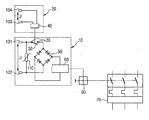
- the embodiment of the auxiliary release illustrated in FIG. 1 consists essentially of the undervoltage release 10 indicated in a respective field and the voltage release 30 arranged on it.
- the release 30 is arranged on the connection 20 in the circuit of the undervoltage release 10 at this.
- the voltage release 30 comprises a relay 40, which acts on a arranged on the junction 20 switching element 50.
- the undervoltage release 10 includes a coil 80 which applies a force to an actuator (not shown), the movement of which is transmitted to a mechanical actuator 60.
- This mechanical actuator 60 transmits a mechanical movement to a power switch 70.
- an adjustable resistor 110 is disposed in the undervoltage release 10 between the first terminal 101 and the second terminal 102.
- a current correspondingly flowing through a rectifier bridge 90 causes a movement of an actuator in the coil 80.
- the movement of the actuator is, as described, transmitted via the mechanical actuator 60 to the contacts of the circuit breaker 70, so that its contacts are opened.
- the circuit breaker can be switched off or tripped. This facility has the advantage that when renewed concern of the voltage of the circuit breaker remains open, so that an uncontrolled startup of a machine is prevented.
- the relay 40 of the tripping device 30 When a voltage is applied to the third terminal 103 and the fourth terminal 104, which exceeds a certain trigger voltage of the tripping device 30, the relay 40 of the tripping device 30 is actuated, the movement of which is transferred to the circuit 50 of the undervoltage release 10 arranged switching element.
- the result of this is a movement of the actuator on the coil 80 of the undervoltage release 10 as already described above in such a way that the contacts of the circuit breaker 70 are opened via the mechanical actuation element 60.
- the power switch 70 can be turned off or triggered when, for example, in the total energy system of the circuit breaker 70 is applied too high a voltage.
Landscapes
- Breakers (AREA)
Description
- Die Erfindung betrifft einen Hilfsauslöser für einen Leistungsschalter. Der Hilfsauslöser kann zum Beispiel als Zubehörteil für einen Niederspannungskompaktleistungsschalter verwendet werden.
- Es besteht die Anforderung an moderne Leistungsschalter, dass diese die Funktionen eines Spannungsauslösers und eines Unterspannungsauslösers in einem Gerät, z.B. in einem Niederspannungskompaktleistungsschalter, kombinieren. Ein Unterspannungsauslöser schaltet ab, wenn keine beziehungsweise eine Spannung unter einem definierten Wert an ihm anliegt. Dadurch können z.B. nach Stromausfall unkontrollierte Wiederanläufe von Maschinen verhindert werden.
- Ein Spannungsauslöser schaltet ab, wenn an ihm eine Spannung anliegt, die einen bestimmten Wert überschreitet.
- Der mit Unterspannungsauslöser und Spannungsauslöser ausgerüstete Leistungsschalter soll möglichst eine extrem kompakte Bauweise aufweisen. Dabei sind teilweise die Hüllmaße einzelner Leistungsschaltertypen bereits festgelegt und es müssen in derartige Leistungsschalter noch weitere Hilfs- und Alarmschalter integriert werden. Außerdem besteht ein Zielkonflikt zwischen der Forderung eines nur geringen Steuerstroms und gleichzeitiger hoher Zuverlässigkeit des resultierenden Schaltzustandes des Leistungsschalters, das heißt, es ist gefordert, mit geringen Steuerströmen eine derartige mechanische Bewegung der Schaltelemente des Leistungsschalters zu erzeugen, dass dieser den gewünschten Schaltzustand zuverlässig erreicht und stabil hält.
- Es ist bekannt, die genannten Funktionen durch den Einbau eines Spannungsauslösers und eines Unterspannungsauslösers als zwei interne Zubehörteile im Leistungsschalter zu realisieren. Beide Zubehörteile haben dabei eine jeweils eigene mechanische Kopplungsstelle an das Betätigungselement für den Leistungsschalter, das heißt, bei herkömmlicher Ausrüstung des Leistungsschalters mit einem Spannungsauslöser und einem Unterspannungsauslöser bestehen zwei Übergabepunkte zwischen dem jeweiligen Auslöser und dem mechanischen Betätigungselement. Ein solcher Auslöser ist aus dem Dokument
-
EP-A-1 122 758 bekannt. - Der Erfindung liegt daher die Aufgabe zugrunde, einen Hilfsauslöser zur Verfügung zu stellen, der mit einfachem und kostengünstigem Aufbau die Möglichkeit bietet, die Funktion eines Unterspannungsauslösers und die Funktion eines Spannungsauslösers bei geringem Energiebedarf und hoher Auslösezuverlässigkeit in einem Gerät mit geringen Hüllmaßen zu vereinigen.
- Die Aufgabe wird durch die im Anspruch 1 genannten Merkmale der Erfindung gelöst. Vorteilhafte Ausgestaltungen der Erfindung sind in den Unteransprüchen angegeben.
- Es wird ein Hilfsauslöser für einen Leistungsschalter zur Verfügung gestellt, wobei der Hilfsauslöser einen Unterspannungsauslöser zur mechanischen Betätigung eines Betätigungselementes umfasst und im Stromkreis des Unterspannungsauslösers eine Anschlussstelle zum Anschluss eines Spannungsauslösers angeordnet ist.
- Üblicherweise weist der Unterspannungsauslöser eine Spule auf, die im stromdurchflossenen Zustand eine Kraft auf ein Stellelement ausübt. Der Stromkreis, in dem der Spannungsauslöser integrierbar ist, ist damit der Stromkreis, in dem die Spule des Unterspannungsauslösers angeordnet ist. Die Bewegung des Stellelements an oder in der Spule wird mechanisch auf das Betätigungselement übertragen. Das Betätigungselement ist dabei z.B. ein mechanisches Schaltschloss eines Leistungsschalters, welches den Leistungsschalter auslöst oder schaltet, das heißt die Kontakte des Leistungsschalters in geöffnete Position bringt.
- Durch die Möglichkeit der Integration des Spannungsauslösers in den Stromkreis des Unterspannungsauslösers ergibt sich eine Flexibilität des Hilfsauslösers dahingehend, dass er in einer Ausführungsform ohne Spannungsauslöser und in einer anderen Ausführungsform mit einem integrierten Spannungsauslöser verwendet werden kann. Das heißt, dass der erfindungsgemäße Hilfsauslöser im Bedarfsfall mit einem Spannungsauslöser nachgerüstet werden kann.
- In einer vorteilhaften Ausgestaltung umfasst der Hilfsauslöser des Weiteren einen Spannungsauslöser, der an die Anschlussstelle im Stromkreis des Unterspannungsauslösers angeschlossen ist und der eine Unterbrechung des Stromkreises dann bewirkt, wenn eine bestimmte an ihn angelegte Spannung überschritten ist.
- Das heißt, dass ein Spannungsauslöser und ein Unterspannungsauslöser in einem Zubehörteil für einen Leistungsschalter vereinigt sind. Der Spannungsauslöser wird dabei durch einen externen Stromimpuls betätigt. Der Spannungsauslöser und der Unterspannungsauslöser definieren unterschiedliche, voneinander unabhängige Steuer-Spannungsbereiche, in denen der Leistungsschalter geschlossen bleiben beziehungsweise ausgelöst/ausgeschaltet werden soll.
- Es wird eine Volumenersparnis im Innenraum des Leistungsschalters dadurch erreicht, dass nur ein Modul, in welchem die Funktionen des Spannungsauslösers und des Unterspannungsauslösers vereinigt sind, eingesetzt wird. Durch die einfache Fertigungsmöglichkeit des beide Funktionen erfüllenden Moduls werden Fertigungskosten eingespart. Gleichzeitig erhöht sich die Zuverlässigkeit der Schaltung, da nur eine Schnittstelle zwischen Hilfsauslöser und mechanischer Auslösewelle des Betätigungselementes existiert.
- Des Weiteren werden Materialkosten gespart, da trotz Erfüllung von zwei Auslösefunktionen in einem Hilfsauslöser nur eine Auslösespule, ein Stellelement und ein Übertragungsmechanismus zur Übertragung der durch den Unterspannungsauslöser ausgelösten Schaltbewegung auf den Leistungsschalter vorhanden sind.
- Außerdem besteht wenig Energiebedarf zur Auslösung des Spannungsauslösers, da dessen Öffnungsfunktion bereits durch Halbleiterbauelemente oder auch durch sehr kleine Spulen realisiert werden kann.
- Der Einsatz des erfindungsgemäßen Hilfsauslösers beschränkt sich nicht auf Niederspannungskompaktleistungsschalter MCCB (moulded case circuit breaker), sondern er kann auch bei Leistungsschaltern unterschiedlicher Größe und Leistung wie zum Beispiel bei offenen Leistungsschaltern ACB (air circuit breaker) eingesetzt werden.
- In einer Ausgestaltung der Anordnung des Spannungsauslösers im Stromkreis des Unterspannungsauslösers ist vorgesehen, dass der Spannungsauslöser unlösbar an die Anschlussstelle im Stromkreis angeschlossen ist. Das heißt, dass der erfindungsgemäße Hilfsauslöser mit integriertem Spannungsauslöser hergestellt ist.
- In einer alternativen Ausgestaltung dazu ist vorgesehen, dass ein als Modul ausgestalteter Spannungsauslöser an die Anschlussstelle im Stromkreis des Unterspannungsauslösers lösbar angeschlossen ist. Durch die nachträgliche Nachrüstbarkeit mit einem modularen Spannungsauslöser lassen sich Produktionskosten senken und die Flexibilität des Unterspannungsauslösers erhöhen.
- Es kann allerdings auch vorgesehen sein, dass ein Spannungsauslöser in modularer Bauweise fest an die Anschlussstelle angeschlossen werden kann.
- In einer weiteren vorteilhaften Ausgestaltung ist vorgesehen, dass der Spannungsauslöser als das den Stromkreis unterbrechende Bauteil ein Halbleiterbauelement umfasst. In dieser konstruktiven Ausgestaltung existiert damit nur eine Spule im erfindungsgemäßen Hilfsauslöser, nämlich die Spule des Unterspannungsauslösers. Das heißt, dass trotz der Vereinigung von zwei Auslöserfunktionen nur eine Spule Energie verbraucht.
- In einer alternativen Ausgestaltung zur Anordnung eines Halbleiterbauelementes ist vorgesehen, dass der Spannungsauslöser als das den Stromkreis unterbrechende Bauteil ein Relais umfasst.
- Diese Ausführungsform hat den Vorteil der galvanischen Trennung der Kontakte des Stromkreises des Unterspannungsauslösers. Zwar ist hier neben der Spule des Unterspannungsauslösers im Relais eine weitere Spule angeordnet, aber diese Spule kann derart dimensioniert sein, dass sie die Öffnungsfunktion des Stromkreises des Unterspannungsauslösers auch mit geringem Stromverbrauch gewährleistet.
- Vorteilhafterweise ist die Auslösespannung des Relais einstellbar. Damit lässt sich der Wert einstellen, bei dem der Spannungsauslöser den Stromkreis des Unterspannungsauslösers unterbricht und dieser wiederum mittels seines Stellgliedes ein Betätigungselement betätigt, welches die Öffnung des Leistungsschalters bewirkt.
- Des Weiteren ist in einer besonderen Ausgestaltung vorgesehen, dass der Spannungsauslöser bei einer Spannung auslöst, die mindestens 55 % der Bemessungsspannung beträgt. Mit dieser Ausgestaltung wird der Spannungsauslöser verschärften Anforderungen, die in bestimmten Wirtschaftsgebieten gestellt werden, gerecht.
- In einer weiteren konstruktiven Ausgestaltung des erfindungsgemäßen Hilfsauslösers ist vorgesehen, dass der Hilfsauslöser des Weiteren ein Schaltelement und einen an dieses Schaltelement mechanisch gekoppelten Spannungsauslöser umfasst, wobei das Schaltelement an die Anschlussstelle im Stromkreis angeschlossen ist und der Spannungsauslöser eine Unterbrechung des Stromkreises dann bewirkt, wenn eine bestimmte an ihn angelegte Spannung überschritten ist. In dieser Ausgestaltung öffnet nicht der Spannungsauslöser selbst den Stromkreis des Unterspannungsauslösers, sondern er betätigt ein Schaltelement, welches bevorzugt ein Öffner ist, und dieses öffnet den Stromkreis.
- Die Erfindung wird anhand der beiliegenden Zeichnung beschrieben. Es zeigt:
- FIG 1
- eine schematische Darstellung des erfindungsgemäßen Hilfsauslösers, welcher über ein mechanisches Betätigungselement an einen Leistungsschalter gekoppelt ist.
- Die in FIG 1 dargestellte Ausführungsform des Hilfsauslösers besteht im Wesentlichen aus dem in jeweils einem Feld angedeuteten Unterspannungsauslöser 10 und dem an ihm angeordneten Spannungsauslöser 30. Der Spannungsauslöser 30 ist über die Anschlussstelle 20 im Stromkreis des Unterspannungsauslösers 10 an diesem angeordnet. In der dargestellten Ausführungsform umfasst der Spannungsauslöser 30 ein Relais 40, welches auf ein an die Anschlussstelle 20 angeordnetes Schaltelement 50 wirkt.
- Der Unterspannungsauslöser 10 umfasst eine Spule 80, die eine Kraft auf ein Stellglied (nicht dargestellt) ausübt, dessen Bewegung auf ein mechanisches Betätigungselement 60 übertragen wird. Dieses mechanische Betätigungselement 60 überträgt eine mechanische Bewegung auf einen Leistungsschalter 70. Des Weiteren ist im Unterspannungsauslöser 10 zwischen der ersten Anschlussklemme 101 und der zweiten Anschlussklemme 102 ein verstellbarer Widerstand 110 angeordnet.
- Sinkt die am Unterspannungsauslöser an dessen erster Anschlussklemme 101 und zweiten Anschlussklemme 102 angelegte Spannung unter einen definierten Wert, bewirkt ein dementsprechend über eine Gleichrichterbrücke 90 fließender Strom in der Spule 80 eine Bewegung eines Stellgliedes. Die Bewegung des Stellgliedes wird, wie beschrieben, über das mechanische Betätigungselement 60 auf die Kontakte des Leistungsschalters 70 übertragen, so dass dessen Kontakte geöffnet werden. So kann bei einer Spannungsunterbrechung, zum Beispiel in einem Havariefall, der Leistungsschalter ausgeschaltet beziehungsweise ausgelöst werden. Diese Einrichtung hat den Vorteil, dass bei erneutem Anliegen der Spannung der Leistungsschalter weiterhin geöffnet bleibt, so dass ein unkontrolliertes Anlaufen einer Maschine verhindert wird.
- Bei Anlage einer Spannung an der dritten Anschlussklemme 103 und der vierten Anschlussklemme 104, die eine bestimmte Auslösespannung des Spannungsauslösers 30 übersteigt, wird das Relais 40 des Spannungsauslösers 30 betätigt, dessen Bewegung auf das im Stromkreis des Unterspannungsauslösers 10 angeordnete Schaltelement 50 übertragen wird. Damit öffnet das Schaltelement 50 den Stromkreis des Unterspannungsauslösers 10. Die Folge davon ist eine wie oben schon beschriebene Bewegung des Stellgliedes an der Spule 80 des Unterspannungsauslösers 10 dahingehend, dass über das mechanische Betätigungselement 60 die Kontakte des Leistungsschalters 70 geöffnet werden. Mit dieser Ausgestaltung kann somit der Leistungsschalter 70 ausgeschaltet beziehungsweise ausgelöst werden, wenn zum Beispiel im Gesamtenergiesystem des Leistungsschalters 70 eine zu hohe Spannung anliegt.
Claims (9)
- Hilfsauslöser für einen Leistungsschalter (70), wobei der Hilfsauslöser einen Unterspannungsauslöser (10) zur mechanischen Betätigung eines Betätigungselementes (60) umfasst,
dadurch gekennzeichnet, dass
im Stromkreis des Unterspannungsauslösers (10) eine Anschlussstelle (20) zum Anschluss eines Spannungsauslösers (30) angeordnet ist. - Hilfsauslöser nach Anspruch 1,
dadurch gekennzeichnet, dass
der Hilfsauslöser des Weiteren einen Spannungsauslöser (30) umfasst, der an die Anschlussstelle (20) im Stromkreis des Unterspannungsauslösers (10) angeschlossen ist und der eine Unterbrechung des Stromkreises dann bewirkt, wenn eine bestimmte an ihn angelegte Spannung überschritten ist. - Hilfsauslöser nach Anspruch 2,
dadurch gekennzeichnet, dass
der Spannungsauslöser (30) unlösbar an die Anschlussstelle (20) im Stromkreis des Unterspannungsauslösers (10) angeschlossen ist. - Hilfsauslöser nach Anspruch 2,
dadurch gekennzeichnet, dass
der Spannungsauslöser (30) als Modul ausgestaltet an die Anschlussstelle (20) im Stromkreis des Unterspannungsauslösers (10) lösbar angeschlossen ist. - Hilfsauslöser nach einem der Ansprüche 2 bis 4,
dadurch gekennzeichnet, dass
der Spannungsauslöser (30) als das den Stromkreis unterbrechende Bauteil ein Halbleiterbauelement umfasst. - Hilfsauslöser nach einem der Ansprüche 2 bis 4,
dadurch gekennzeichnet, dass
der Spannungsauslöser (30) als das den Stromkreis unterbrechende Bauteil ein Relais (40) umfasst. - Hilfsauslöser nach Anspruch 6,
dadurch gekennzeichnet, dass
die Auslösespannung des Relais (40) einstellbar ist. - Hilfsauslöser nach einem der Ansprüche 2 bis 7,
dadurch gekennzeichnet, dass
der Spannungsauslöser (30) bei einer Spannung auslöst, die mindestens 55 % der Bemessungsspannung beträgt. - Hilfsauslöser nach Anspruch 1,
dadurch gekennzeichnet, dass
der Hilfsauslöser des Weiteren ein Schaltelement (50) und einen an dieses Schaltelement (50) mechanisch gekoppelten Spannungsauslöser (30) umfasst, wobei das Schaltelement (50) an die Anschlussstelle (20) im Stromkreis angeschlossen ist und der Spannungsauslöser (30) eine Unterbrechung des Stromkreises dann bewirkt, wenn eine bestimmte an ihn angelegte Spannung überschritten ist.
Applications Claiming Priority (1)
| Application Number | Priority Date | Filing Date | Title |
|---|---|---|---|
| PCT/DE2006/001685 WO2008034398A1 (de) | 2006-09-21 | 2006-09-21 | Hilfsauslöser für einen leistungsschalter |
Publications (2)
| Publication Number | Publication Date |
|---|---|
| EP2064724A1 EP2064724A1 (de) | 2009-06-03 |
| EP2064724B1 true EP2064724B1 (de) | 2014-06-18 |
Family
ID=37946228
Family Applications (1)
| Application Number | Title | Priority Date | Filing Date |
|---|---|---|---|
| EP06805336.2A Not-in-force EP2064724B1 (de) | 2006-09-21 | 2006-09-21 | Hilfsauslöser für einen leistungsschalter |
Country Status (5)
| Country | Link |
|---|---|
| US (1) | US20090237187A1 (de) |
| EP (1) | EP2064724B1 (de) |
| CN (1) | CN101512704A (de) |
| DE (1) | DE112006004150A5 (de) |
| WO (1) | WO2008034398A1 (de) |
Families Citing this family (11)
| Publication number | Priority date | Publication date | Assignee | Title |
|---|---|---|---|---|
| KR20120071537A (ko) * | 2010-12-23 | 2012-07-03 | 엘에스산전 주식회사 | 배선용 차단기의 트립 장치 |
| CN102760620B (zh) * | 2011-04-27 | 2016-03-02 | 施耐德电器工业公司 | 用于断路器的辅助脱扣器及采用该辅助脱扣器的断路器 |
| CN102761095B (zh) * | 2011-04-28 | 2015-09-23 | 西门子公司 | 欠压-过压保护装置及方法 |
| CN102761096B (zh) * | 2011-04-28 | 2015-10-14 | 西门子公司 | 欠压-过压保护装置及方法 |
| CN103094877B (zh) * | 2011-10-28 | 2015-08-19 | 西门子公司 | 欠压-过压保护装置及方法 |
| DE102011089211A1 (de) * | 2011-12-20 | 2013-01-31 | Siemens Aktiengesellschaft | Schalter, insbesondere Leistungsschalter für Niederspannungen |
| CN104377094B (zh) * | 2012-07-02 | 2016-08-24 | 常州工学院 | 一种低功耗欠压脱扣器 |
| CN103675416B (zh) * | 2012-09-03 | 2016-08-31 | 西门子公司 | 欠压-过压保护装置及方法 |
| CN104078923B (zh) * | 2013-03-28 | 2017-07-21 | 海洋王(东莞)照明科技有限公司 | 过欠压保护电路及照明装置 |
| CN104201653A (zh) * | 2014-08-29 | 2014-12-10 | 山东超越数控电子有限公司 | 一种有分段电压处理功能的电池欠压保护电路及保护方法 |
| CN109950101B (zh) * | 2019-04-10 | 2024-03-22 | 宏秀电气有限公司 | 户外高压断路器的操作机构及户外高压断路器及使用方法 |
Family Cites Families (6)
| Publication number | Priority date | Publication date | Assignee | Title |
|---|---|---|---|---|
| US4788621A (en) * | 1987-12-16 | 1988-11-29 | General Electric Company | Molded case circuit breaker multiple accessory unit |
| GB9414869D0 (en) * | 1994-07-23 | 1994-09-14 | Delta Circuits Protection | Module for use with a circuit breaker |
| DE10004597A1 (de) * | 2000-02-03 | 2001-08-09 | Kopp Heinrich Ag | Hilfsstromauslöser für Leitungs-, Fehlerstrom- und Motorschutzschalter |
| EP1154538A1 (de) * | 2000-05-10 | 2001-11-14 | Siemens Aktiengesellschaft | Unter- und/oder Überspannungsauslöser |
| DE10254038A1 (de) * | 2002-11-20 | 2004-06-03 | Moeller Gmbh | Hilfsauslöser für Motorschutzschalter |
| US7262516B2 (en) * | 2005-07-15 | 2007-08-28 | General Electric Company | Methods and systems for operating engine generator sets |
-
2006
- 2006-09-21 EP EP06805336.2A patent/EP2064724B1/de not_active Not-in-force
- 2006-09-21 US US12/311,126 patent/US20090237187A1/en not_active Abandoned
- 2006-09-21 CN CNA2006800559014A patent/CN101512704A/zh active Pending
- 2006-09-21 DE DE112006004150T patent/DE112006004150A5/de not_active Withdrawn
- 2006-09-21 WO PCT/DE2006/001685 patent/WO2008034398A1/de not_active Ceased
Also Published As
| Publication number | Publication date |
|---|---|
| WO2008034398A1 (de) | 2008-03-27 |
| EP2064724A1 (de) | 2009-06-03 |
| DE112006004150A5 (de) | 2009-09-03 |
| CN101512704A (zh) | 2009-08-19 |
| US20090237187A1 (en) | 2009-09-24 |
Similar Documents
| Publication | Publication Date | Title |
|---|---|---|
| EP2048679B1 (de) | Lasttrenner-Anordnung | |
| EP1186084B1 (de) | Elektrische schalteinrichtung zum überstromschutz | |
| EP2020014B1 (de) | Schalteinrichtung | |
| EP1380042B1 (de) | Schaltgeräteeinheit für einen verbraucher, insbesondere motorstarter | |
| EP2064724B1 (de) | Hilfsauslöser für einen leistungsschalter | |
| DE10244961B3 (de) | Selektiver Leitungsschutzschalter | |
| WO2005020259A1 (de) | Sicherungsbehaftetes schaltschutzgerät | |
| EP2070100B1 (de) | Schaltmechanik einer fehlerstromschutzeinrichtung, fehlerstromschutzeinrichtung sowie system mit einer fehlerstromschutzeinrichtung und einem leitungsschutzschalter | |
| DE2854637C2 (de) | Als Gruppenschutzschalter dienendes elektrisches Installationsschaltgerät | |
| EP2769399B1 (de) | Bauareihe mehrpoliger leistungsschalter | |
| EP2112677A2 (de) | Voll-Schutzschalter | |
| AT406531B (de) | Fehlerstromschutzschalter | |
| EP4677632A1 (de) | Laststufenschalter und verfahren zur betätigung | |
| DE102008017932A1 (de) | Installationsschalter und Stromzählersystem | |
| EP3293751B1 (de) | Schaltschloss für ein niederspannungsschutzgerät | |
| EP1721375B1 (de) | Schutzgerät für einen verbraucherabzweig | |
| DE2945683A1 (de) | Leitungsschalter | |
| DE102019220433B4 (de) | Rückstellelement und elektrischer Schalter mit solch einem Rückstellelement | |
| DE102012201677A1 (de) | Elektrisches Schaltgerät, insbesondere Leistungsschalter | |
| DE69225127T2 (de) | Selektiver automatischer Sicherheitsschalter | |
| WO2025093210A1 (de) | Elektronisch schaltendes niederspannungs-schutzschaltgerät | |
| DE102024109252A1 (de) | Elektronische Sicherung zum Vermeiden eines unerwünschten dauerhaften Abschaltens von elektrischen Verbrauchern bei Überlastverhalten | |
| CH547003A (de) | Nulleiter-abschalteinrichtung fuer ein zwei- oder mehrpoliges abschaltgeraet. | |
| DE102008017273B4 (de) | Elektrischer Selbstschalter | |
| WO2025093212A1 (de) | Schaltmechanismus sowie elektronisch schaltendes niederspannungs-schutzschaltgerät |
Legal Events
| Date | Code | Title | Description |
|---|---|---|---|
| PUAI | Public reference made under article 153(3) epc to a published international application that has entered the european phase |
Free format text: ORIGINAL CODE: 0009012 |
|
| 17P | Request for examination filed |
Effective date: 20090203 |
|
| AK | Designated contracting states |
Kind code of ref document: A1 Designated state(s): AT BE BG CH CY CZ DE DK EE ES FI FR GB GR HU IE IS IT LI LT LU LV MC NL PL PT RO SE SI SK TR |
|
| AX | Request for extension of the european patent |
Extension state: AL BA HR MK RS |
|
| DAX | Request for extension of the european patent (deleted) | ||
| RAP1 | Party data changed (applicant data changed or rights of an application transferred) |
Owner name: SIEMENS AKTIENGESELLSCHAFT |
|
| GRAP | Despatch of communication of intention to grant a patent |
Free format text: ORIGINAL CODE: EPIDOSNIGR1 |
|
| INTG | Intention to grant announced |
Effective date: 20140116 |
|
| GRAS | Grant fee paid |
Free format text: ORIGINAL CODE: EPIDOSNIGR3 |
|
| GRAA | (expected) grant |
Free format text: ORIGINAL CODE: 0009210 |
|
| AK | Designated contracting states |
Kind code of ref document: B1 Designated state(s): AT BE BG CH CY CZ DE DK EE ES FI FR GB GR HU IE IS IT LI LT LU LV MC NL PL PT RO SE SI SK TR |
|
| REG | Reference to a national code |
Ref country code: GB Ref legal event code: FG4D Free format text: NOT ENGLISH |
|
| REG | Reference to a national code |
Ref country code: CH Ref legal event code: EP |
|
| REG | Reference to a national code |
Ref country code: AT Ref legal event code: REF Ref document number: 673776 Country of ref document: AT Kind code of ref document: T Effective date: 20140715 |
|
| REG | Reference to a national code |
Ref country code: IE Ref legal event code: FG4D Free format text: LANGUAGE OF EP DOCUMENT: GERMAN |
|
| REG | Reference to a national code |
Ref country code: DE Ref legal event code: R096 Ref document number: 502006013811 Country of ref document: DE Effective date: 20140724 |
|
| PG25 | Lapsed in a contracting state [announced via postgrant information from national office to epo] |
Ref country code: FI Free format text: LAPSE BECAUSE OF FAILURE TO SUBMIT A TRANSLATION OF THE DESCRIPTION OR TO PAY THE FEE WITHIN THE PRESCRIBED TIME-LIMIT Effective date: 20140618 Ref country code: GR Free format text: LAPSE BECAUSE OF FAILURE TO SUBMIT A TRANSLATION OF THE DESCRIPTION OR TO PAY THE FEE WITHIN THE PRESCRIBED TIME-LIMIT Effective date: 20140919 Ref country code: CY Free format text: LAPSE BECAUSE OF FAILURE TO SUBMIT A TRANSLATION OF THE DESCRIPTION OR TO PAY THE FEE WITHIN THE PRESCRIBED TIME-LIMIT Effective date: 20140618 Ref country code: LT Free format text: LAPSE BECAUSE OF FAILURE TO SUBMIT A TRANSLATION OF THE DESCRIPTION OR TO PAY THE FEE WITHIN THE PRESCRIBED TIME-LIMIT Effective date: 20140618 |
|
| REG | Reference to a national code |
Ref country code: NL Ref legal event code: VDEP Effective date: 20140618 |
|
| REG | Reference to a national code |
Ref country code: LT Ref legal event code: MG4D |
|
| PG25 | Lapsed in a contracting state [announced via postgrant information from national office to epo] |
Ref country code: LV Free format text: LAPSE BECAUSE OF FAILURE TO SUBMIT A TRANSLATION OF THE DESCRIPTION OR TO PAY THE FEE WITHIN THE PRESCRIBED TIME-LIMIT Effective date: 20140618 Ref country code: SE Free format text: LAPSE BECAUSE OF FAILURE TO SUBMIT A TRANSLATION OF THE DESCRIPTION OR TO PAY THE FEE WITHIN THE PRESCRIBED TIME-LIMIT Effective date: 20140618 |
|
| PG25 | Lapsed in a contracting state [announced via postgrant information from national office to epo] |
Ref country code: EE Free format text: LAPSE BECAUSE OF FAILURE TO SUBMIT A TRANSLATION OF THE DESCRIPTION OR TO PAY THE FEE WITHIN THE PRESCRIBED TIME-LIMIT Effective date: 20140618 Ref country code: RO Free format text: LAPSE BECAUSE OF FAILURE TO SUBMIT A TRANSLATION OF THE DESCRIPTION OR TO PAY THE FEE WITHIN THE PRESCRIBED TIME-LIMIT Effective date: 20140618 Ref country code: CZ Free format text: LAPSE BECAUSE OF FAILURE TO SUBMIT A TRANSLATION OF THE DESCRIPTION OR TO PAY THE FEE WITHIN THE PRESCRIBED TIME-LIMIT Effective date: 20140618 Ref country code: SK Free format text: LAPSE BECAUSE OF FAILURE TO SUBMIT A TRANSLATION OF THE DESCRIPTION OR TO PAY THE FEE WITHIN THE PRESCRIBED TIME-LIMIT Effective date: 20140618 Ref country code: PT Free format text: LAPSE BECAUSE OF FAILURE TO SUBMIT A TRANSLATION OF THE DESCRIPTION OR TO PAY THE FEE WITHIN THE PRESCRIBED TIME-LIMIT Effective date: 20141020 Ref country code: ES Free format text: LAPSE BECAUSE OF FAILURE TO SUBMIT A TRANSLATION OF THE DESCRIPTION OR TO PAY THE FEE WITHIN THE PRESCRIBED TIME-LIMIT Effective date: 20140618 |
|
| PG25 | Lapsed in a contracting state [announced via postgrant information from national office to epo] |
Ref country code: IS Free format text: LAPSE BECAUSE OF FAILURE TO SUBMIT A TRANSLATION OF THE DESCRIPTION OR TO PAY THE FEE WITHIN THE PRESCRIBED TIME-LIMIT Effective date: 20141018 Ref country code: PL Free format text: LAPSE BECAUSE OF FAILURE TO SUBMIT A TRANSLATION OF THE DESCRIPTION OR TO PAY THE FEE WITHIN THE PRESCRIBED TIME-LIMIT Effective date: 20140618 Ref country code: NL Free format text: LAPSE BECAUSE OF FAILURE TO SUBMIT A TRANSLATION OF THE DESCRIPTION OR TO PAY THE FEE WITHIN THE PRESCRIBED TIME-LIMIT Effective date: 20140618 |
|
| REG | Reference to a national code |
Ref country code: DE Ref legal event code: R097 Ref document number: 502006013811 Country of ref document: DE |
|
| PLBE | No opposition filed within time limit |
Free format text: ORIGINAL CODE: 0009261 |
|
| STAA | Information on the status of an ep patent application or granted ep patent |
Free format text: STATUS: NO OPPOSITION FILED WITHIN TIME LIMIT |
|
| PG25 | Lapsed in a contracting state [announced via postgrant information from national office to epo] |
Ref country code: DK Free format text: LAPSE BECAUSE OF FAILURE TO SUBMIT A TRANSLATION OF THE DESCRIPTION OR TO PAY THE FEE WITHIN THE PRESCRIBED TIME-LIMIT Effective date: 20140618 Ref country code: LU Free format text: LAPSE BECAUSE OF FAILURE TO SUBMIT A TRANSLATION OF THE DESCRIPTION OR TO PAY THE FEE WITHIN THE PRESCRIBED TIME-LIMIT Effective date: 20140921 Ref country code: IT Free format text: LAPSE BECAUSE OF FAILURE TO SUBMIT A TRANSLATION OF THE DESCRIPTION OR TO PAY THE FEE WITHIN THE PRESCRIBED TIME-LIMIT Effective date: 20140618 Ref country code: MC Free format text: LAPSE BECAUSE OF FAILURE TO SUBMIT A TRANSLATION OF THE DESCRIPTION OR TO PAY THE FEE WITHIN THE PRESCRIBED TIME-LIMIT Effective date: 20140618 |
|
| REG | Reference to a national code |
Ref country code: CH Ref legal event code: PL |
|
| 26N | No opposition filed |
Effective date: 20150319 |
|
| GBPC | Gb: european patent ceased through non-payment of renewal fee |
Effective date: 20140921 |
|
| REG | Reference to a national code |
Ref country code: IE Ref legal event code: MM4A |
|
| REG | Reference to a national code |
Ref country code: FR Ref legal event code: ST Effective date: 20150529 |
|
| PG25 | Lapsed in a contracting state [announced via postgrant information from national office to epo] |
Ref country code: BE Free format text: LAPSE BECAUSE OF NON-PAYMENT OF DUE FEES Effective date: 20140930 |
|
| PG25 | Lapsed in a contracting state [announced via postgrant information from national office to epo] |
Ref country code: GB Free format text: LAPSE BECAUSE OF NON-PAYMENT OF DUE FEES Effective date: 20140921 Ref country code: LI Free format text: LAPSE BECAUSE OF NON-PAYMENT OF DUE FEES Effective date: 20140930 Ref country code: SI Free format text: LAPSE BECAUSE OF FAILURE TO SUBMIT A TRANSLATION OF THE DESCRIPTION OR TO PAY THE FEE WITHIN THE PRESCRIBED TIME-LIMIT Effective date: 20140618 Ref country code: CH Free format text: LAPSE BECAUSE OF NON-PAYMENT OF DUE FEES Effective date: 20140930 |
|
| PG25 | Lapsed in a contracting state [announced via postgrant information from national office to epo] |
Ref country code: IE Free format text: LAPSE BECAUSE OF NON-PAYMENT OF DUE FEES Effective date: 20140921 Ref country code: FR Free format text: LAPSE BECAUSE OF NON-PAYMENT OF DUE FEES Effective date: 20140930 |
|
| REG | Reference to a national code |
Ref country code: AT Ref legal event code: MM01 Ref document number: 673776 Country of ref document: AT Kind code of ref document: T Effective date: 20140921 |
|
| PG25 | Lapsed in a contracting state [announced via postgrant information from national office to epo] |
Ref country code: AT Free format text: LAPSE BECAUSE OF NON-PAYMENT OF DUE FEES Effective date: 20140921 |
|
| PG25 | Lapsed in a contracting state [announced via postgrant information from national office to epo] |
Ref country code: BG Free format text: LAPSE BECAUSE OF FAILURE TO SUBMIT A TRANSLATION OF THE DESCRIPTION OR TO PAY THE FEE WITHIN THE PRESCRIBED TIME-LIMIT Effective date: 20140618 |
|
| PG25 | Lapsed in a contracting state [announced via postgrant information from national office to epo] |
Ref country code: HU Free format text: LAPSE BECAUSE OF FAILURE TO SUBMIT A TRANSLATION OF THE DESCRIPTION OR TO PAY THE FEE WITHIN THE PRESCRIBED TIME-LIMIT; INVALID AB INITIO Effective date: 20060921 Ref country code: TR Free format text: LAPSE BECAUSE OF FAILURE TO SUBMIT A TRANSLATION OF THE DESCRIPTION OR TO PAY THE FEE WITHIN THE PRESCRIBED TIME-LIMIT Effective date: 20140618 |
|
| PGFP | Annual fee paid to national office [announced via postgrant information from national office to epo] |
Ref country code: DE Payment date: 20201118 Year of fee payment: 15 |
|
| REG | Reference to a national code |
Ref country code: DE Ref legal event code: R119 Ref document number: 502006013811 Country of ref document: DE |
|
| PG25 | Lapsed in a contracting state [announced via postgrant information from national office to epo] |
Ref country code: DE Free format text: LAPSE BECAUSE OF NON-PAYMENT OF DUE FEES Effective date: 20220401 |