EP2064781B1 - System und verfahren zum verstärkungsausgleich und zugehöriges optisches kommunikationssystem - Google Patents
System und verfahren zum verstärkungsausgleich und zugehöriges optisches kommunikationssystem Download PDFInfo
- Publication number
- EP2064781B1 EP2064781B1 EP07842869.5A EP07842869A EP2064781B1 EP 2064781 B1 EP2064781 B1 EP 2064781B1 EP 07842869 A EP07842869 A EP 07842869A EP 2064781 B1 EP2064781 B1 EP 2064781B1
- Authority
- EP
- European Patent Office
- Prior art keywords
- edfa
- raman
- gain
- pump
- amplifier
- Prior art date
- Legal status (The legal status is an assumption and is not a legal conclusion. Google has not performed a legal analysis and makes no representation as to the accuracy of the status listed.)
- Not-in-force
Links
- 230000003287 optical effect Effects 0.000 title claims description 59
- 230000006854 communication Effects 0.000 title claims description 12
- 238000004891 communication Methods 0.000 title claims description 12
- 238000000034 method Methods 0.000 title claims description 9
- 238000001069 Raman spectroscopy Methods 0.000 claims description 76
- 230000005540 biological transmission Effects 0.000 claims description 39
- 239000000835 fiber Substances 0.000 claims description 29
- 238000005086 pumping Methods 0.000 claims description 7
- XLYOFNOQVPJJNP-UHFFFAOYSA-N water Substances O XLYOFNOQVPJJNP-UHFFFAOYSA-N 0.000 claims description 5
- 230000002269 spontaneous effect Effects 0.000 claims description 4
- 238000001914 filtration Methods 0.000 description 13
- 238000003199 nucleic acid amplification method Methods 0.000 description 8
- 230000003321 amplification Effects 0.000 description 7
- 238000001228 spectrum Methods 0.000 description 6
- 230000008901 benefit Effects 0.000 description 5
- 238000010586 diagram Methods 0.000 description 3
- UYAHIZSMUZPPFV-UHFFFAOYSA-N erbium Chemical compound [Er] UYAHIZSMUZPPFV-UHFFFAOYSA-N 0.000 description 3
- 229910052691 Erbium Inorganic materials 0.000 description 2
- 238000013459 approach Methods 0.000 description 2
- 230000000593 degrading effect Effects 0.000 description 2
- 239000006185 dispersion Substances 0.000 description 2
- 230000001902 propagating effect Effects 0.000 description 2
- 240000008213 Brosimum alicastrum Species 0.000 description 1
- 238000010521 absorption reaction Methods 0.000 description 1
- 230000002411 adverse Effects 0.000 description 1
- 238000005452 bending Methods 0.000 description 1
- 230000007175 bidirectional communication Effects 0.000 description 1
- 230000008859 change Effects 0.000 description 1
- 230000008878 coupling Effects 0.000 description 1
- 238000010168 coupling process Methods 0.000 description 1
- 238000005859 coupling reaction Methods 0.000 description 1
- 230000001419 dependent effect Effects 0.000 description 1
- 238000013461 design Methods 0.000 description 1
- 238000001514 detection method Methods 0.000 description 1
- 229910003460 diamond Inorganic materials 0.000 description 1
- 239000010432 diamond Substances 0.000 description 1
- 230000006872 improvement Effects 0.000 description 1
- 238000003780 insertion Methods 0.000 description 1
- 230000037431 insertion Effects 0.000 description 1
- 239000003550 marker Substances 0.000 description 1
- 230000008569 process Effects 0.000 description 1
- 230000000750 progressive effect Effects 0.000 description 1
- 235000005828 ramon Nutrition 0.000 description 1
- 238000002834 transmittance Methods 0.000 description 1
Images

Classifications
-
- H—ELECTRICITY
- H01—ELECTRIC ELEMENTS
- H01S—DEVICES USING THE PROCESS OF LIGHT AMPLIFICATION BY STIMULATED EMISSION OF RADIATION [LASER] TO AMPLIFY OR GENERATE LIGHT; DEVICES USING STIMULATED EMISSION OF ELECTROMAGNETIC RADIATION IN WAVE RANGES OTHER THAN OPTICAL
- H01S3/00—Lasers, i.e. devices using stimulated emission of electromagnetic radiation in the infrared, visible or ultraviolet wave range
- H01S3/23—Arrangements of two or more lasers not provided for in groups H01S3/02 - H01S3/22, e.g. tandem arrangements of separate active media
- H01S3/2375—Hybrid lasers
-
- H—ELECTRICITY
- H01—ELECTRIC ELEMENTS
- H01S—DEVICES USING THE PROCESS OF LIGHT AMPLIFICATION BY STIMULATED EMISSION OF RADIATION [LASER] TO AMPLIFY OR GENERATE LIGHT; DEVICES USING STIMULATED EMISSION OF ELECTROMAGNETIC RADIATION IN WAVE RANGES OTHER THAN OPTICAL
- H01S3/00—Lasers, i.e. devices using stimulated emission of electromagnetic radiation in the infrared, visible or ultraviolet wave range
- H01S3/05—Construction or shape of optical resonators; Accommodation of active medium therein; Shape of active medium
- H01S3/06—Construction or shape of active medium
- H01S3/063—Waveguide lasers, i.e. whereby the dimensions of the waveguide are of the order of the light wavelength
- H01S3/067—Fibre lasers
- H01S3/06754—Fibre amplifiers
- H01S3/06758—Tandem amplifiers
-
- H—ELECTRICITY
- H01—ELECTRIC ELEMENTS
- H01S—DEVICES USING THE PROCESS OF LIGHT AMPLIFICATION BY STIMULATED EMISSION OF RADIATION [LASER] TO AMPLIFY OR GENERATE LIGHT; DEVICES USING STIMULATED EMISSION OF ELECTROMAGNETIC RADIATION IN WAVE RANGES OTHER THAN OPTICAL
- H01S3/00—Lasers, i.e. devices using stimulated emission of electromagnetic radiation in the infrared, visible or ultraviolet wave range
- H01S3/30—Lasers, i.e. devices using stimulated emission of electromagnetic radiation in the infrared, visible or ultraviolet wave range using scattering effects, e.g. stimulated Brillouin or Raman effects
- H01S3/302—Lasers, i.e. devices using stimulated emission of electromagnetic radiation in the infrared, visible or ultraviolet wave range using scattering effects, e.g. stimulated Brillouin or Raman effects in an optical fibre
-
- H—ELECTRICITY
- H04—ELECTRIC COMMUNICATION TECHNIQUE
- H04B—TRANSMISSION
- H04B10/00—Transmission systems employing electromagnetic waves other than radio-waves, e.g. infrared, visible or ultraviolet light, or employing corpuscular radiation, e.g. quantum communication
- H04B10/29—Repeaters
- H04B10/291—Repeaters in which processing or amplification is carried out without conversion of the main signal from optical form
- H04B10/2912—Repeaters in which processing or amplification is carried out without conversion of the main signal from optical form characterised by the medium used for amplification or processing
- H04B10/2916—Repeaters in which processing or amplification is carried out without conversion of the main signal from optical form characterised by the medium used for amplification or processing using Raman or Brillouin amplifiers
-
- H—ELECTRICITY
- H04—ELECTRIC COMMUNICATION TECHNIQUE
- H04B—TRANSMISSION
- H04B10/00—Transmission systems employing electromagnetic waves other than radio-waves, e.g. infrared, visible or ultraviolet light, or employing corpuscular radiation, e.g. quantum communication
- H04B10/29—Repeaters
- H04B10/291—Repeaters in which processing or amplification is carried out without conversion of the main signal from optical form
- H04B10/293—Signal power control
- H04B10/294—Signal power control in a multiwavelength system, e.g. gain equalisation
- H04B10/2941—Signal power control in a multiwavelength system, e.g. gain equalisation using an equalising unit, e.g. a filter
-
- H—ELECTRICITY
- H01—ELECTRIC ELEMENTS
- H01S—DEVICES USING THE PROCESS OF LIGHT AMPLIFICATION BY STIMULATED EMISSION OF RADIATION [LASER] TO AMPLIFY OR GENERATE LIGHT; DEVICES USING STIMULATED EMISSION OF ELECTROMAGNETIC RADIATION IN WAVE RANGES OTHER THAN OPTICAL
- H01S2301/00—Functional characteristics
- H01S2301/04—Gain spectral shaping, flattening
Definitions
- the present application relates to the optical transmission of information and, more particularly, to a system and method for gain equalization and an optical communication system incorporating the same.
- long-haul optical communication systems e.g. systems of lengths greater than about 600 kilometers, suffer from signal attenuation resulting from a variety of factors, including scattering, absorption, and bending.
- long-haul systems may include a series of optical amplifiers spaced along the transmission path between a transmitter and a receiver. The amplifiers amplify the optical signal in a manner allowing reliable detection at the receiver.
- Erbium doped fiber amplifiers have proven particularly useful in long-haul systems.
- an EDFA includes an erbium-doped fiber segment that is "pumped" with light from one or more pump sources.
- the pump source e.g. a laser, excites erbium atoms in the doped segment, which then serve to amplify the optical signal passing therethrough.
- Raman amplifiers are also known. Raman amplification occurs throughout an optical transmission fiber segment when it is pumped at an appropriate wavelength or wavelengths. Each Raman amplifier may contain one or more pumps. Gain is achieved over a spectrum of wavelengths longer than the pump wavelength through the process of Stimulated Raman Scattering. Although the power efficiency associated with Raman amplifiers is less than that achieved by EDFAs, Raman amplifiers may provide better noise performance by means of distributed amplification in the transmission fiber.
- Hybrid Raman/EDFA (HRE) amplifiers combine the features of both Raman and EDFA amplifiers.
- a Raman portion typically acts as a pre-amplifier before an EDFA.
- the addition of Raman amplification to an EDFA configuration allows for an economical increase in spacing between amplifiers on the transmission path compared to use of EDFAs alone.
- WDM wavelength division multiplexed
- several optical signals are transmitted on the same fiber at different wavelengths/channels.
- the optical amplifiers in a WDM system should amplify each channel within the system bandwidth at the same level of gain. If the transmitted channels are non-uniformly amplified, channels may ultimately be lost due to progressive under-amplification as they propagate in the transmission path.
- Gain flattening filters render the gain level substantially flat across the system bandwidth.
- a gain flattening filter may be provided between EDFA stages.
- gain flattening filters have been provided at the output of the EDFA portion of the HRE.
- Long-haul undersea systems may consist of very long spans and subsequently be pump power limited. That is, the pump power available for an amplifier may be practically limited to a maximum level below that which would be necessary to achieve optimum transmission performance. In such a system incorporating HREs, in order to receive the full benefits of Raman pre-amplification, it may be desirable to make efficient use of the limited pump power.
- FIG. 6 includes plots 600 of signal power vs. wavelength illustrating the power lost in equalization using a post-filtering approach.
- Plot 602 illustrates an EDFA output power spectrum provided at the input of a gain flattening filter
- plot 604 illustrates the power spectrum at the output of the gain flattening filter.
- the region 606 between plot 602 and plot 604 represents the loss in signal power resulting from post-filtering.
- the power spectrum 604 at the output filter is flattened compared to the power spectrum 602 at the input of the filter, gain flattening is achieved with a significant loss of signal power.
- 5.65 dBm of signal power is effectively wasted by a post-filtering approach.
- US 2002/0131160 discloses a dispersion managed long-haul high-speed optical network, with distributed Raman amplification to obtain a transmission reach of 2000km or more, with sections having individual spans of 80 - 100km. The final span of each section comprises Ramon amplification followed by a dispersion gain flattening filter and then an optical amplifier.
- the hybrid fiber amplifier also comprises a gain flattening filter connected between the DCF Raman amplifier and the power-boosting EDA.
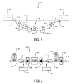
- FIG. 1 there is illustrated an exemplary optical communication system 100 consistent with the present invention.
- system 100 has been depicted as a highly simplified point-to-point system for ease of explanation. It is to be understood the present invention may be incorporated into a wide variety of optical networks and systems.
- the illustrated exemplary optical communication system 100 includes a transmitter 102 and a receiver 106 connected via an optical transmission path 104.
- a plurality of separate optical signals may be generated by modulating data on each of a plurality of different wavelengths/channels within a signal bandwidth.
- the transmitter 102 may combine the separate channels into an aggregate optical signal and transmit the aggregate optical signal over the optical information path 104 to the receiver 106.
- the system 100 is illustrated as including a distinct transmitter 102 and receiver 106, those of ordinary skill in the art will recognize the transmitter 102 and receiver 106 may each be configured as a transceiver to facilitate bidirectional communication over the optical information path.
- the optical transmission path 104 may include, optical transmission fiber 110, optical amplifiers/repeaters 108-1, 108-2, 108-3, 108-(N-1), 108-N consistent with the present invention, optical filters, and other active and passive components.
- optical amplifiers/repeaters 108-1, 108-2, 108-3, 108-(N-1), 108-N and optical transmission fiber 110 are illustrated in the optical information path 104.
- Optical amplifier configurations consistent with the present invention will be described in greater detail herein. Configurations for other components included in the transmission path are known to those of ordinary skill in the art.
- System 100 may be configured as a long-haul system, e.g. having a length from the transmitter to receiver of more than about 600km, and may span a body of water 112.
- amplifiers/repeaters 108-1, 108-2, 108-3, 108-(N-1), 108-N may be seated on the ocean floor 114 and the transmission path 104 may span between beach landings 116, 118 to extend from the water 112 for coupling to the transmitter 102 and receiver 106.
- a plurality of optical transmission components may be coupled to the transmission path 104 and may be disposed beneath water and/or over land.
- the distance between optical amplifiers defines a transmission span length.
- the illustrated exemplary embodiment includes a plurality of spans, 124-1, 124-2, 123-3...124-(I-1), 124-I.
- span lengths may vary significantly in a particular system. In a long-haul system, for example, some spans may be as short as 20 kilometers, while some spans may exceed 100km. In view of the span length variation, signal attenuation varies from span-to-span.
- the amplifiers 108-1, 108-2, 108-3, 108-(N-1), 108-N may be configured to compensate for the signal attenuation by amplifying the optical signal wavelengths in the signal bandwidth.
- One exemplary embodiment of an amplifier 108 consistent with the present invention is illustrated in FIG. 2 .
- the illustrated exemplary embodiment is configured as a hybrid Raman/EDFA amplifier (HRE) including a Raman amplifier portion 202 and an EDFA portion 204.
- the Raman portion 202 may include a transmission fiber segment 206 in which Raman gain is generated for amplifying an optical signal propagating through the path 104.
- Energy from one or more Raman pump sources 210 may be coupled to the segment 206 of transmission fiber 110 by a coupler 208.
- the EDFA portion 204 may be a single or multi-stage EDFA, and may include one or more EDFA pump sources 212, a coupler 214, an erbium-doped fiber segment 216, and an isolator 218.
- EDFA pump sources 212 may include one or more EDFA pump sources 212, a coupler 214, an erbium-doped fiber segment 216, and an isolator 218.
- Raman and EDFA pump sources that may be controlled locally or remotely are known to those of ordinary skill in the art.
- the pump sources may be coupled to the optical path 104 in a known configuration.
- the illustrated exemplary embodiment includes a gain flattening filter (GFF) 220 coupled between the Raman portion 202 and the EDFA portion 204 (referred to herein as pre-filtering).
- GFF gain flattening filter
- the output of the Raman portion 202 is optically coupled to the input of the GFF through an isolator 222 and the input of the EDFA portion 204 is optically coupled to the output of the GFF through an isolator 224.
- the GFF receives the amplified output of the Raman portion and provides an input to the EDFA portion having a reshaped spectrum compared to the input received by the GFF from the Raman portion.
- the GFF insertion loss profile may be designed to flatten the combined gain shapes of the Raman and EDFA sections.
- the transmittance characteristics of the GFF may be selected in consideration of the gain characteristics of the Raman 202 and EDFA 204 gain portions such that amplification of the output of the GFF by the EDFA portion 204 provides an amplifier output 226 that is flattened to a desired level.
- GFF configurations including one or more separate filter elements for reducing the gain vs. wavelength variation of a signal applied to an input thereof are known.
- the extent of gain flattening achieved by a GFF in particular application consistent with the present invention may be highly dependent on the total gain shape of the input to the filter, the specific filter configuration, etc.
- gain may be flattened to exhibit a variation of less than about 1dB peak-peak. For amplifiers with large amounts of gain compensating losses of very long spans, the flattened gain variation may be worse compared to cases with shorter spans.
- available pump power for pumping an EDFA portion of an HRE may be practically limited to less than about 400 mW.
- transmission spans in excess of 120 km may be achieved using a pump power for the EDFA portion of less than about 400 mW.
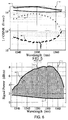
- FIG. 3 includes plots 300 on a log scale of simulated reciprocal of optical signal to noise ratios (1/OSNR) vs. span length showing the levels of ASE and MPI generated by the Raman and EDFA portions of pre-filtered HREs designed for 96 channels, consistent with the present invention.
- each marker represents a channel.
- the circular markers 302, 308, and 314 illustrate the ASE generated in the Raman portion of the HRE
- the square markers 304, 312, and 318 illustrate the ASE generated in the EDFA portion of the HRE
- the diamond markers 306, 310 and 316 illustrate the MPI generated in the Raman portion of the HRE.
- the ASE noise from the Raman portion of the HRE is dominant over the ASE noise from the EDFA portion of the HRE.
- the EDFA portion exhibits a more extreme gain shape and a wider range of OSNR, but the ASE generated in the Raman portion remains more than twice the level of the ASE in the EDFA.
- noise from the Raman portion dominates the noise from the EDFA portion, providing a GFF between a Raman portion and an EDFA portion has minimal adverse impact on the total amplifier noise performance compared to providing a GFF at the output of the EDFA portion.
- higher signal power may be launched into the transmission path using reasonable pump powers and without significantly degrading the total noise performance of the system.
- FIG. 4 includes plots 400 on a log scale of the reciprocal of optical signal to noise ratio (1/OSNR) vs. wavelength for a 150 km HRE employing pre-filtering consistent with the present invention.
- Plots 402 and 404 show the levels of ASE and MPI, respectively, generated by the Raman portion and plot 406 shows the level of ASE generated by the EDFA portion.
- Plot 408 shows the total amplifier noise performance resulting from the Raman ASE 402 and MPI 404 and the EDFA ASE 406.
- FIG. 5 includes plots 500 on a log scale of the reciprocal of optical signal to noise ratio (1/OSNR) vs. wavelength for a HRE employing post-filtering.
- Plots 502 and 504 show the levels of ASE and MPI, respectively, generated by the Raman portion and plot 506 shows the ASE generated by the EDFA portion.
- Plot 508 shows the total amplifier noise performance resulting from the Raman ASE 502 and MPI 504 and the EDFA ASE 506.
- the plots set forth in FIGS. 4 and 5 were generated using data derived from simulated system including 96 channels using HREs with a total launch power of 21 dBm, calculated for a single amplifier.
- the Raman portion of the simulated HRE was pumped at 1450 nm and the EDFA portion was pumped at 980 nm.
- the GFFs in the simulated systems contributed an average loss of 5.3dB in the illustrated signal bandwidth and a peak loss of 7.9 dB.
- the EDFA pump power was set at 295 mW.
- the EDFA pump power was set at 1072 mW.
- the noise contributions from the Raman portion 402, 404 and 502,504 were dominant relative to the ASE noise generated by the EDFA 406, 506, and do not change with location of the GFF.
- a system consistent with the present invention thus allows use of significantly less pump power than a system including a GFF at the output of an EDFA portion without significantly effecting system noise performance.
- pump power is limited, e.g. in a long-haul undersea system, the efficiencies associated with a system consistent with the present invention may provide a significant advantage in system reach compared to a system including a GFF at the output of an EDFA portion.
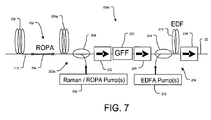
- FIG. 7 illustrates an amplifier/repeater configuration 108a wherein Raman gain generated in a segment of transmission fiber 206a of a Raman portion 202a is supplemented by gain from a ROPA 702.
- ROPA configurations are known to those of ordinary skill in the art, and generally include a doped fiber segment 704, e.g. an erbium doped fiber segment, embedded in the transmission fiber 110.
- the doped fiber segment 704 is disposed between transmission fiber segments 708 and 206a.
- One or more pump sources may pump the transmission fiber segment 206a and the doped fiber segment 704 for amplifying an optical signal propagating through the segments.
- a single Raman/ROPA pump source 706 is provided in the amplifier/repeater 108a. Energy for pumping both the segment 206a and the doped segment 704 may be coupled from the pump source 706 by a coupler 208.
- gain is imparted to the signal through pumping of the doped fiber segment 704 and Raman gain is imparted through pumping of the transmission fiber segment 206a.
- the doped segment 704 of the ROPA may be physically located in the transmission path at a distance of 20-120km from the pump source 706.
- Raman/ROPA pump source 706 Although a single Raman/ROPA pump source 706 is illustrated, separate pump sources may be provided for the Raman portion 202a and the ROPA 702. Also, the Raman and/or ROPA pump sources may be physically located in a repeater, e.g.108a, or in a system terminal 102 or 106.
- a gain flattening filter (GFF) 220 is provided between the Raman portion 202a and an EDFA portion 204 to provide pre-filtering. Since the total amplifier noise may be dominated by the ROPA and Raman ASE noise components, pre-filtering while avoiding a GFF at the output of the EDFA portion 204 provides benefits associated with pump power efficiency, as described above.
- GFF gain flattening filter
- an optical communication system according to any one of the appended claims 1 to 8, and a method according to any one of the appended claims 9 and 10.
Landscapes
- Physics & Mathematics (AREA)
- Electromagnetism (AREA)
- Engineering & Computer Science (AREA)
- Plasma & Fusion (AREA)
- Optics & Photonics (AREA)
- Computer Networks & Wireless Communication (AREA)
- Signal Processing (AREA)
- Optical Communication System (AREA)
- Lasers (AREA)
- Optical Modulation, Optical Deflection, Nonlinear Optics, Optical Demodulation, Optical Logic Elements (AREA)
Claims (10)
- Optisches Kommunikationssystem (100), das umfasst:einen Sender (102), der so konfiguriert ist, dass er ein optisches Summensignal sendet, das eine Mehrzahl von optischen Signalen in unterschiedlichen zugehörigen Wellenlängen in einer Signalbandbereite umfasst;einen Empfänger (106), der so konfiguriert ist, dass er das optische Summensignal empfängt und Daten erfasst, die auf der Mehrzahl von optischen Signalen moduliert sind; undeinen Übertragungspfad (104), der sich zwischen dem Sender und dem Empfänger erstreckt, wobei der Übertragungspfad umfasst:zumindest einen ersten und einen zweiten Verstärker (108_1, 108_2), die durch eine Übertragungsspanne (124_2) getrennt sind, wobei zumindest der erste Verstärker (108_1) ein Hybrid-Raman-/EDFA-Verstärker ist, der umfasst:einen Raman-Abschnitt (202), der ein Übertragungspfadsegment (206) umfasst, das so konfiguriert ist, dass es von zumindest einer Raman-Pumpe (210) gepumpt wird, um zumindest einen Abschnitt der Signalbandbreite mittels Raman-Verstärkung zu verstärken,einen EDFA-Abschnitt (204), um zumindest einen Abschnitt der Signalbandbreite zu verstärken,undein Filter (220) zum Abflachen der Verstärkung, das zwischen dem Raman-Abschnitt und dem EDFA-Abschnitt des Hybrid-Raman/EDFA verbunden ist, wobei kein Filter zum Abflachen der Verstärkung mit einem Ausgang (226) des EDFA-Abschnitts verbunden ist, wodurchder EDFA-Abschnitt (204) zumindest eine erbiumdotierte Faser (216) umfasst, die so konfiguriert ist, dass sie durch zumindest eine EDFA-Pumpe (212) gepumpt wird, und die durch den Abschnitt (204) erzielte Verstärkung eine EDFA-Verstärkung ist;die Übertragungsspanne (124_2) zumindest 120 km lang ist; unddie zumindest eine Raman-Pumpe (210) und die zumindest eine EDFA-Pumpe (212) so konfiguriert sind, dass sie das Übertragungspfadsegment (206) bzw. das erbiumdotierte Fasersegment (216) pumpen, um einen Verstärkungsfaktor zu erreichen, wobei das vom Raman-Abschnitt erzeugte Rauschen der verstärkten spontanen Emission (ASE) das vom EDFA-Abschnitt erzeugte ASE-Rauschen übersteigt.
- System nach Anspruch 1, wobei die zumindest eine EDFA-Pumpe (212) so konfiguriert ist, dass sie die erbiumdotierte Faser mit einer Pumpleistung von weniger als ungefähr 400 mW pumpt.
- System nach Anspruch 1, wobei der Übertragungspfad (104) eine Länge von zumindest 600 km aufweist, um ein Gewässer zu überspannen.
- System nach Anspruch 1, wobei der erste Verstärker eine einzelne der Raman-Pumpen (210) und eine einzelne der EDFA-Pumpen (212) umfasst.
- System nach Anspruch 1, wobei die zumindest eine Raman-Pumpe (210) so konfiguriert ist, dass sie das Übertragungsfasersegment (206) bei einer Wellenlänge von ungefähr 1450 nm pumpt, und wobei die zumindest eine EDFA-Pumpe (212) so konfiguriert ist, dass sie die erbiumdotierte Faser (216) bei einer Wellenlänge von ungefähr 980 nm pumpt.
- System nach Anspruch 1, wobei das Filter (220) zum Abflachen der Verstärkung durch einen ersten Isolator (222) mit einem Ausgang des Raman-Abschnitts (108) verbunden ist und durch einen zweiten Isolator (224) mit einem Eingang des EDFA-Abschnitts (204) verbunden ist.
- System nach Anspruch 1, wobei das System ferner einen optischen gepumpten Remote-Verstärker (702) umfasst, der ein dotiertes Segment (704) des Übertragungspfads umfasst, wobei das dotierte Segment so konfiguriert ist, dass es durch zumindest eine Pumpe (706) gepumpt wird, um zumindest einen Abschnitt der Signalbandbreite zu verstärken.
- System nach Anspruch 10, wobei die zumindest eine Pumpe (706) die zumindest eine Raman-Pumpe umfasst.
- Verfahren zum Verstärken eines optischen Signals, um das Signal auf einer Übertragungsspanne (124_2) von zumindest 120 km unter Verwendung eines Hybrid-Raman-/EDFA-Verstärkers (108_1) zu starten, der einen Raman-Verstärkungsabschnitt (202) mit einem Ausgang enthält, der mit einem Eingang eines EDFA-Verstärkungsabschnitts (204) verbunden ist, wobei das Verfahren umfasst:Abflachen des Verstärkungsfaktors nur zwischen dem Raman-Verstärkungsabschnitt und dem EDFA-Verstärkungsabschnitt des Hybrid-Raman-/EDFA-Verstärkers;Pumpen des EDFA-Abschnitts (204) mit einer Pumpleistung von weniger als ungefähr 400 mW; undPumpen des Raman-Abschnitts (202), um einen Verstärkungsfaktor zu erreichen, wobei das vom Raman-Abschnitt (202) erzeugte Rauschen der verstärkten spontanen Emission (ASE) das vom EDFA-Abschnitt (204) erzeugte ASE-Rauschen übersteigt.
- Verfahren nach Anspruch 9, wobei der Verstärker einen optischen gepumpten Remote-Verstärker (706) enthält, und wobei das Verfahren ferner das Pumpen des Raman-Abschnitts (202a) und des optischen gepumpten Remote-Verstärkers (706) umfasst, um einen Verstärkungsfaktor zu erreichen, wobei das vom Raman-Abschnitt und vom Abschnitt des optischen Remote-Verstärkers erzeugte Rauschen der verstärkten spontanen Emission (ASE) das vom EDFA-Abschnitt erzeugte ASE-Rauschen übersteigt.
Applications Claiming Priority (2)
| Application Number | Priority Date | Filing Date | Title |
|---|---|---|---|
| US11/534,026 US7924497B2 (en) | 2006-09-21 | 2006-09-21 | System and method for gain equalization and optical communication system incorporating the same |
| PCT/US2007/079006 WO2008036804A2 (en) | 2006-09-21 | 2007-09-20 | System and method for gain equalization and optical communication system incorporating the same |
Publications (3)
| Publication Number | Publication Date |
|---|---|
| EP2064781A2 EP2064781A2 (de) | 2009-06-03 |
| EP2064781A4 EP2064781A4 (de) | 2012-09-19 |
| EP2064781B1 true EP2064781B1 (de) | 2015-12-09 |
Family
ID=39205204
Family Applications (1)
| Application Number | Title | Priority Date | Filing Date |
|---|---|---|---|
| EP07842869.5A Not-in-force EP2064781B1 (de) | 2006-09-21 | 2007-09-20 | System und verfahren zum verstärkungsausgleich und zugehöriges optisches kommunikationssystem |
Country Status (6)
| Country | Link |
|---|---|
| US (1) | US7924497B2 (de) |
| EP (1) | EP2064781B1 (de) |
| JP (1) | JP5036009B2 (de) |
| CN (1) | CN101517847B (de) |
| ES (1) | ES2560867T3 (de) |
| WO (1) | WO2008036804A2 (de) |
Families Citing this family (15)
| Publication number | Priority date | Publication date | Assignee | Title |
|---|---|---|---|---|
| US7869673B2 (en) * | 2008-08-29 | 2011-01-11 | Xtera Communications, Inc. | Remote larger effective area optical fiber |
| KR101337560B1 (ko) * | 2009-08-18 | 2013-12-06 | 한국전자통신연구원 | 원격 광 증폭된 수동형 광 네트워크 시스템, 광회선단말, 원격노드 및 이를 이용한 광 증폭 방법 및 이득 고정방법 |
| US8643941B2 (en) * | 2009-12-14 | 2014-02-04 | Finisar Israel Ltd. | Automatic measurement and gain control of distributed Raman amplifiers |
| US8576481B2 (en) * | 2010-08-03 | 2013-11-05 | Finisar Israel Ltd. | Method and apparatus of detecting an opening in an optical transmission fiber of a ROPA system |
| CN106464381B (zh) * | 2014-03-19 | 2019-08-13 | 海王星海底Ip有限公司 | 具有远程光学泵浦式放大器的多区段光通信链路 |
| US9231365B1 (en) * | 2014-06-12 | 2016-01-05 | Ofs Fitel, Llc | Discrete raman amplifier |
| US10297970B2 (en) * | 2016-04-10 | 2019-05-21 | Lijie Qiao | Optical amplifier |
| CN105762625B (zh) * | 2016-05-13 | 2018-08-21 | 无锡市德科立光电子技术有限公司 | 一种可现场配置及升级的放大器装置 |
| CN106067654B (zh) * | 2016-07-22 | 2021-10-29 | 中国电子科技集团公司第三十四研究所 | 一种基于1950nm激光器的远端泵浦掺铒光纤放大器 |
| US11349275B2 (en) * | 2018-06-12 | 2022-05-31 | Ofs Fitel, Llc | Complementary optical fiber-based amplifiers with built-in gain flattening |
| CN108808431B (zh) * | 2018-07-11 | 2020-09-22 | 电子科技大学 | 一种基于弱掺铒光纤的混合随机激光分布式放大方法 |
| CN112134622B (zh) * | 2020-09-23 | 2022-04-01 | 北京邮电大学 | 一种用于光纤时频同步的高增益低噪声Raman+EDFA混合双向中继系统 |
| CN112968349A (zh) * | 2021-03-16 | 2021-06-15 | 东莞先进光纤应用技术研究院有限公司 | 一种单芯双向通信系统的双向光放大器 |
| CN115314112A (zh) * | 2021-05-07 | 2022-11-08 | 华为技术有限公司 | 一种光放大器、光信号放大及光放大器增益调节的方法及系统 |
| US11824588B1 (en) * | 2023-04-20 | 2023-11-21 | Attochron, Llc | Reducing scintillation noise in free-space optical communications |
Citations (1)
| Publication number | Priority date | Publication date | Assignee | Title |
|---|---|---|---|---|
| JP2005070522A (ja) * | 2003-08-26 | 2005-03-17 | Kddi Submarine Cable Systems Inc | 複合光増幅器 |
Family Cites Families (36)
| Publication number | Priority date | Publication date | Assignee | Title |
|---|---|---|---|---|
| WO1998036479A1 (en) * | 1997-02-18 | 1998-08-20 | Nippon Telegraph And Telephone Corporation | Optical amplifier and transmission system using the same |
| US5920424A (en) * | 1997-02-18 | 1999-07-06 | Lucent Technologies Inc. | Article comprising a broadband optical fiber amplifier |
| US6038356A (en) * | 1997-09-25 | 2000-03-14 | Tyco Submarine Systems Ltd. | Lightwave transmission system employing raman and rare-earth doped fiber amplification |
| KR100328291B1 (ko) * | 1998-07-14 | 2002-08-08 | 노베라 옵틱스 인코포레이티드 | 능동제어된파장별이득을갖는광증폭기및변화가능한출력스펙트럼을갖는광섬유광원 |
| US6728026B2 (en) * | 1998-07-14 | 2004-04-27 | Novera Optics, Inc. | Dynamically tunable optical amplifier and fiber optic light source |
| US6525872B1 (en) * | 1999-02-11 | 2003-02-25 | Jds Uniphase Corporation | Fiber grating-stabilized, semiconductor pump source |
| JP3844902B2 (ja) * | 1999-03-02 | 2006-11-15 | 富士通株式会社 | 波長多重用光増幅器及び光通信システム |
| JP3527671B2 (ja) * | 1999-04-23 | 2004-05-17 | 富士通株式会社 | ラマン増幅による光伝送パワーの波長特性制御方法、並びに、それを用いた波長多重光通信システムおよび光増幅器 |
| GB9911665D0 (en) * | 1999-05-19 | 1999-07-21 | Cit Alcatel | An optical amplifier |
| US6396624B1 (en) * | 2000-01-11 | 2002-05-28 | Tycom (Us) Inc. | Extended band erbium doped fiber amplifier |
| US6657774B1 (en) * | 2000-08-18 | 2003-12-02 | Corning Incorporated | Amplifier system with distributed and discrete Raman fiber amplifiers |
| US6724524B1 (en) * | 2000-08-18 | 2004-04-20 | Corning Incorporated | Gain control in Raman amplifiers |
| US6396623B1 (en) * | 2000-12-19 | 2002-05-28 | Onetta, Inc. | Wide-band optical amplifiers with interleaved gain stages |
| GB0031508D0 (en) * | 2000-12-22 | 2001-02-07 | Cit Alcatel | Broadband raman amplifier |
| CA2340848A1 (en) * | 2001-03-15 | 2002-09-15 | John D. Mcnicol | Dispersion management for long-haul high-speed optical networks |
| US20020149838A1 (en) * | 2001-04-11 | 2002-10-17 | Quan-Zhen Wang | Optical amplification system or group employing multiple pump laser groupings |
| US6529315B2 (en) * | 2001-04-27 | 2003-03-04 | Sycamore Networks, Inc | Optical amplifier providing dispersion compensation |
| JP2002341390A (ja) * | 2001-05-17 | 2002-11-27 | Mitsubishi Electric Corp | 光中継装置および光伝送システム |
| US6556345B1 (en) * | 2001-06-21 | 2003-04-29 | Onetta, Inc. | Optical network equipment with control and data paths |
| ATE389981T1 (de) * | 2001-07-20 | 2008-04-15 | Alcatel Lucent | Verstärkungsentzerrung in einem optischen übertragungssystem |
| US20030021009A1 (en) * | 2001-07-25 | 2003-01-30 | Maccormack Stuart | Wide dynamic range EDFA |
| US6621619B2 (en) * | 2001-07-30 | 2003-09-16 | The United States Of America As Represented By The Secretary Of The Navy | Hybrid brillouin/erbium doped fiber amplifier apparatus and method |
| CN2496195Y (zh) * | 2001-08-16 | 2002-06-19 | 华为技术有限公司 | 一种光中继设备 |
| KR100407825B1 (ko) * | 2002-02-23 | 2003-12-01 | 한국전자통신연구원 | 저잡음 분산보상 하이브리드 형 광섬유 증폭기 |
| US6665114B2 (en) * | 2002-02-26 | 2003-12-16 | Corning Incorporated | Hybrid Raman-erbium optical amplifier |
| US6865018B2 (en) * | 2002-03-04 | 2005-03-08 | Inplane Photonics, Inc. | Multistage optical amplifier having a fiber-based amplifier stage and a planar waveguide-based amplifier stage |
| CA2422206C (en) * | 2002-03-15 | 2011-06-14 | Tyco Telecommunications (Us) Inc. | Hybrid raman/erbium-doped fiber amplifier and transmission system with dispersion map |
| JP4194815B2 (ja) * | 2002-09-04 | 2008-12-10 | 株式会社フジクラ | 光増幅器 |
| US20040196532A1 (en) * | 2002-12-06 | 2004-10-07 | Evangelides Stephen G. | Undersea optical transmission system employing Raman gain to mitigate shallow water repair penalties |
| KR100462029B1 (ko) * | 2003-03-14 | 2004-12-18 | 한국전자통신연구원 | 광섬유 증폭기 및 이의 제어 방법 |
| US7158287B2 (en) * | 2003-03-26 | 2007-01-02 | Sprint Communications Company L.P. | Distributed and discrete amplification of optical signals |
| EP1478109B1 (de) * | 2003-05-13 | 2005-10-05 | Alcatel | Optischer Verstärker, Übertragungssystem und Verfahren zur Schräglagenregelung in einem Übertragungssystem |
| CN2631132Y (zh) | 2003-07-03 | 2004-08-04 | 复旦大学 | 一种混合型宽带光纤放大器 |
| US7038843B2 (en) * | 2003-08-21 | 2006-05-02 | Lucent Technologies Inc. | Method and system for reducing Raman gain tilt error |
| KR100581058B1 (ko) * | 2003-09-19 | 2006-05-22 | 한국전자통신연구원 | 광섬유 증폭기 |
| JP2006108499A (ja) * | 2004-10-07 | 2006-04-20 | Furukawa Electric Co Ltd:The | 光信号増幅装置及びロススペクトルの決定方法。 |
-
2006
- 2006-09-21 US US11/534,026 patent/US7924497B2/en not_active Expired - Fee Related
-
2007
- 2007-09-20 WO PCT/US2007/079006 patent/WO2008036804A2/en not_active Ceased
- 2007-09-20 JP JP2009529391A patent/JP5036009B2/ja not_active Expired - Fee Related
- 2007-09-20 CN CN2007800352704A patent/CN101517847B/zh not_active Expired - Fee Related
- 2007-09-20 ES ES07842869.5T patent/ES2560867T3/es active Active
- 2007-09-20 EP EP07842869.5A patent/EP2064781B1/de not_active Not-in-force
Patent Citations (1)
| Publication number | Priority date | Publication date | Assignee | Title |
|---|---|---|---|---|
| JP2005070522A (ja) * | 2003-08-26 | 2005-03-17 | Kddi Submarine Cable Systems Inc | 複合光増幅器 |
Also Published As
| Publication number | Publication date |
|---|---|
| US7924497B2 (en) | 2011-04-12 |
| EP2064781A2 (de) | 2009-06-03 |
| JP2010504707A (ja) | 2010-02-12 |
| CN101517847B (zh) | 2012-02-01 |
| CN101517847A (zh) | 2009-08-26 |
| WO2008036804A3 (en) | 2008-11-27 |
| JP5036009B2 (ja) | 2012-09-26 |
| EP2064781A4 (de) | 2012-09-19 |
| US20080074734A1 (en) | 2008-03-27 |
| WO2008036804A2 (en) | 2008-03-27 |
| ES2560867T3 (es) | 2016-02-23 |
Similar Documents
| Publication | Publication Date | Title |
|---|---|---|
| EP2064781B1 (de) | System und verfahren zum verstärkungsausgleich und zugehöriges optisches kommunikationssystem | |
| JP3640289B2 (ja) | 分散ラマン増幅器および遠隔ポンプ式エルビウム・ドープド・ファイバ増幅器を備えた光ファイバ通信システム | |
| CA2414951C (en) | Cascaded pumping system and method for producing distributed raman amplification in optical fiber telecommunication systems | |
| US6038356A (en) | Lightwave transmission system employing raman and rare-earth doped fiber amplification | |
| US7085039B2 (en) | Hybrid Raman/erbium-doped fiber amplifier and transmission system with dispersion map | |
| US20020051285A1 (en) | Broadband amplifier and communication system | |
| JPH11103113A (ja) | 光増幅器 | |
| JP3884744B2 (ja) | 利得平坦化された広帯域エルビウム添加光ファイバ増幅器 | |
| US8081880B2 (en) | Inline pump sharing architecture for remotely-pumped pre- and post-amplifiers | |
| EP1372276A2 (de) | Optischer Raman-Faserverstärker mittels einem Erbium-dotierten Faser | |
| US12149039B2 (en) | Wide gain bandwidth C-band optical fiber amplifier | |
| KR100446541B1 (ko) | 분산 보상된 라만 광섬유 증폭기 | |
| EP1410536B1 (de) | Vorrichtung und verfahren zur edfa-verstärkung mit ramanunterstützung | |
| US20060216035A1 (en) | System and method of dispersion compensation in optical communication systems | |
| US20020131131A1 (en) | Optical communication system using L-band wavelengths | |
| US7158287B2 (en) | Distributed and discrete amplification of optical signals | |
| EP1410537B1 (de) | System und verfahren zur dispersionskompensation in optischen kommunikationssystemen | |
| EP3582412A1 (de) | Komplementäre verstärker auf glasfaserbasis mit eingebauter verstärkungsabflachung | |
| KR100219711B1 (ko) | 평탄한 이득특성을 갖는 광섬유증폭기 | |
| US6567208B1 (en) | Amplification of a C-band and L-band of a optical signal using a common laser signal | |
| JP2008153558A (ja) | 光伝送システム及びその信号スペクトラム補正方法 | |
| Lucero et al. | Advanced repeater architectures with ultra-long spans for submarine systems | |
| Liaw et al. | Investigation of bidirectional-pump power-equalized Raman fiber amplifier with 24-dB gain | |
| HK1121305A (en) | Optical transmission system and signal spectrum correction method | |
| CA2615306A1 (en) | Inline pump sharing architecture for remotely-pumped pre-and post-amplifiers |
Legal Events
| Date | Code | Title | Description |
|---|---|---|---|
| PUAI | Public reference made under article 153(3) epc to a published international application that has entered the european phase |
Free format text: ORIGINAL CODE: 0009012 |
|
| 17P | Request for examination filed |
Effective date: 20090326 |
|
| AK | Designated contracting states |
Kind code of ref document: A2 Designated state(s): AT BE BG CH CY CZ DE DK EE ES FI FR GB GR HU IE IS IT LI LT LU LV MC MT NL PL PT RO SE SI SK TR |
|
| AX | Request for extension of the european patent |
Extension state: AL BA HR MK RS |
|
| DAX | Request for extension of the european patent (deleted) | ||
| RAP1 | Party data changed (applicant data changed or rights of an application transferred) |
Owner name: TYCO ELECTRONICS SUBSEA COMMUNICATIONS LLC |
|
| RAP1 | Party data changed (applicant data changed or rights of an application transferred) |
Owner name: TYCO ELECTRONICS SUBSEA COMMUNICATIONS LLC |
|
| RBV | Designated contracting states (corrected) |
Designated state(s): DE ES FR GB IT |
|
| RIC1 | Information provided on ipc code assigned before grant |
Ipc: H01S 3/23 20060101ALI20120809BHEP Ipc: H01S 3/30 20060101ALI20120809BHEP Ipc: H04B 10/17 20060101ALN20120809BHEP Ipc: H01S 3/067 20060101AFI20120809BHEP |
|
| A4 | Supplementary search report drawn up and despatched |
Effective date: 20120820 |
|
| REG | Reference to a national code |
Ref country code: DE Ref legal event code: R079 Ref document number: 602007044203 Country of ref document: DE Free format text: PREVIOUS MAIN CLASS: H01S0003000000 Ipc: H01S0003067000 |
|
| RIC1 | Information provided on ipc code assigned before grant |
Ipc: H01S 3/23 20060101ALI20150401BHEP Ipc: H01S 3/30 20060101ALI20150401BHEP Ipc: H04B 10/294 20130101ALN20150401BHEP Ipc: H01S 3/067 20060101AFI20150401BHEP |
|
| GRAP | Despatch of communication of intention to grant a patent |
Free format text: ORIGINAL CODE: EPIDOSNIGR1 |
|
| INTG | Intention to grant announced |
Effective date: 20150515 |
|
| RIN1 | Information on inventor provided before grant (corrected) |
Inventor name: NISSOV, MORTEN Inventor name: PILIPETSKII, ALEXEI N. Inventor name: LUCERO,, ALAN J. |
|
| GRAS | Grant fee paid |
Free format text: ORIGINAL CODE: EPIDOSNIGR3 |
|
| RAP1 | Party data changed (applicant data changed or rights of an application transferred) |
Owner name: TYCO ELECTRONICS SUBSEA COMMUNICATIONS LLC |
|
| GRAA | (expected) grant |
Free format text: ORIGINAL CODE: 0009210 |
|
| AK | Designated contracting states |
Kind code of ref document: B1 Designated state(s): DE ES FR GB IT |
|
| REG | Reference to a national code |
Ref country code: GB Ref legal event code: FG4D |
|
| REG | Reference to a national code |
Ref country code: DE Ref legal event code: R096 Ref document number: 602007044203 Country of ref document: DE |
|
| REG | Reference to a national code |
Ref country code: ES Ref legal event code: FG2A Ref document number: 2560867 Country of ref document: ES Kind code of ref document: T3 Effective date: 20160223 |
|
| REG | Reference to a national code |
Ref country code: DE Ref legal event code: R097 Ref document number: 602007044203 Country of ref document: DE |
|
| REG | Reference to a national code |
Ref country code: FR Ref legal event code: PLFP Year of fee payment: 10 |
|
| PLBE | No opposition filed within time limit |
Free format text: ORIGINAL CODE: 0009261 |
|
| STAA | Information on the status of an ep patent application or granted ep patent |
Free format text: STATUS: NO OPPOSITION FILED WITHIN TIME LIMIT |
|
| PGFP | Annual fee paid to national office [announced via postgrant information from national office to epo] |
Ref country code: GB Payment date: 20160927 Year of fee payment: 10 |
|
| 26N | No opposition filed |
Effective date: 20160912 |
|
| PGFP | Annual fee paid to national office [announced via postgrant information from national office to epo] |
Ref country code: FR Payment date: 20160926 Year of fee payment: 10 |
|
| PGFP | Annual fee paid to national office [announced via postgrant information from national office to epo] |
Ref country code: ES Payment date: 20160926 Year of fee payment: 10 |
|
| PGFP | Annual fee paid to national office [announced via postgrant information from national office to epo] |
Ref country code: DE Payment date: 20160928 Year of fee payment: 10 |
|
| PGFP | Annual fee paid to national office [announced via postgrant information from national office to epo] |
Ref country code: IT Payment date: 20160923 Year of fee payment: 10 |
|
| REG | Reference to a national code |
Ref country code: DE Ref legal event code: R119 Ref document number: 602007044203 Country of ref document: DE |
|
| GBPC | Gb: european patent ceased through non-payment of renewal fee |
Effective date: 20170920 |
|
| REG | Reference to a national code |
Ref country code: FR Ref legal event code: ST Effective date: 20180531 |
|
| PG25 | Lapsed in a contracting state [announced via postgrant information from national office to epo] |
Ref country code: GB Free format text: LAPSE BECAUSE OF NON-PAYMENT OF DUE FEES Effective date: 20170920 Ref country code: DE Free format text: LAPSE BECAUSE OF NON-PAYMENT OF DUE FEES Effective date: 20180404 |
|
| PG25 | Lapsed in a contracting state [announced via postgrant information from national office to epo] |
Ref country code: FR Free format text: LAPSE BECAUSE OF NON-PAYMENT OF DUE FEES Effective date: 20171002 Ref country code: IT Free format text: LAPSE BECAUSE OF NON-PAYMENT OF DUE FEES Effective date: 20170920 |
|
| REG | Reference to a national code |
Ref country code: ES Ref legal event code: FD2A Effective date: 20181019 |
|
| PG25 | Lapsed in a contracting state [announced via postgrant information from national office to epo] |
Ref country code: ES Free format text: LAPSE BECAUSE OF NON-PAYMENT OF DUE FEES Effective date: 20170921 |