EP2064802B1 - Magnetisches lager - Google Patents
Magnetisches lager Download PDFInfo
- Publication number
- EP2064802B1 EP2064802B1 EP07809594A EP07809594A EP2064802B1 EP 2064802 B1 EP2064802 B1 EP 2064802B1 EP 07809594 A EP07809594 A EP 07809594A EP 07809594 A EP07809594 A EP 07809594A EP 2064802 B1 EP2064802 B1 EP 2064802B1
- Authority
- EP
- European Patent Office
- Prior art keywords
- magnetic bearing
- electromagnets
- static portion
- radial magnetic
- radial
- Prior art date
- Legal status (The legal status is an assumption and is not a legal conclusion. Google has not performed a legal analysis and makes no representation as to the accuracy of the status listed.)
- Active
Links
Images


Classifications
-
- H—ELECTRICITY
- H02—GENERATION; CONVERSION OR DISTRIBUTION OF ELECTRIC POWER
- H02K—DYNAMO-ELECTRIC MACHINES
- H02K7/00—Arrangements for handling mechanical energy structurally associated with dynamo-electric machines, e.g. structural association with mechanical driving motors or auxiliary dynamo-electric machines
- H02K7/08—Structural association with bearings
- H02K7/09—Structural association with bearings with magnetic bearings
-
- F—MECHANICAL ENGINEERING; LIGHTING; HEATING; WEAPONS; BLASTING
- F16—ENGINEERING ELEMENTS AND UNITS; GENERAL MEASURES FOR PRODUCING AND MAINTAINING EFFECTIVE FUNCTIONING OF MACHINES OR INSTALLATIONS; THERMAL INSULATION IN GENERAL
- F16C—SHAFTS; FLEXIBLE SHAFTS; ELEMENTS OR CRANKSHAFT MECHANISMS; ROTARY BODIES OTHER THAN GEARING ELEMENTS; BEARINGS
- F16C32/00—Bearings not otherwise provided for
- F16C32/04—Bearings not otherwise provided for using magnetic or electric supporting means
- F16C32/0406—Magnetic bearings
- F16C32/044—Active magnetic bearings
- F16C32/0459—Details of the magnetic circuit
-
- F—MECHANICAL ENGINEERING; LIGHTING; HEATING; WEAPONS; BLASTING
- F16—ENGINEERING ELEMENTS AND UNITS; GENERAL MEASURES FOR PRODUCING AND MAINTAINING EFFECTIVE FUNCTIONING OF MACHINES OR INSTALLATIONS; THERMAL INSULATION IN GENERAL
- F16C—SHAFTS; FLEXIBLE SHAFTS; ELEMENTS OR CRANKSHAFT MECHANISMS; ROTARY BODIES OTHER THAN GEARING ELEMENTS; BEARINGS
- F16C32/00—Bearings not otherwise provided for
- F16C32/04—Bearings not otherwise provided for using magnetic or electric supporting means
- F16C32/0406—Magnetic bearings
- F16C32/044—Active magnetic bearings
- F16C32/047—Details of housings; Mounting of active magnetic bearings
-
- F—MECHANICAL ENGINEERING; LIGHTING; HEATING; WEAPONS; BLASTING
- F16—ENGINEERING ELEMENTS AND UNITS; GENERAL MEASURES FOR PRODUCING AND MAINTAINING EFFECTIVE FUNCTIONING OF MACHINES OR INSTALLATIONS; THERMAL INSULATION IN GENERAL
- F16C—SHAFTS; FLEXIBLE SHAFTS; ELEMENTS OR CRANKSHAFT MECHANISMS; ROTARY BODIES OTHER THAN GEARING ELEMENTS; BEARINGS
- F16C32/00—Bearings not otherwise provided for
- F16C32/04—Bearings not otherwise provided for using magnetic or electric supporting means
- F16C32/0406—Magnetic bearings
- F16C32/044—Active magnetic bearings
- F16C32/0474—Active magnetic bearings for rotary movement
- F16C32/0489—Active magnetic bearings for rotary movement with active support of five degrees of freedom, e.g. two radial magnetic bearings combined with an axial bearing
-
- F—MECHANICAL ENGINEERING; LIGHTING; HEATING; WEAPONS; BLASTING
- F16—ENGINEERING ELEMENTS AND UNITS; GENERAL MEASURES FOR PRODUCING AND MAINTAINING EFFECTIVE FUNCTIONING OF MACHINES OR INSTALLATIONS; THERMAL INSULATION IN GENERAL
- F16C—SHAFTS; FLEXIBLE SHAFTS; ELEMENTS OR CRANKSHAFT MECHANISMS; ROTARY BODIES OTHER THAN GEARING ELEMENTS; BEARINGS
- F16C35/00—Rigid support of bearing units; Housings, e.g. caps, covers
-
- H—ELECTRICITY
- H02—GENERATION; CONVERSION OR DISTRIBUTION OF ELECTRIC POWER
- H02K—DYNAMO-ELECTRIC MACHINES
- H02K9/00—Arrangements for cooling or ventilating
- H02K9/22—Arrangements for cooling or ventilating by solid heat conducting material embedded in, or arranged in contact with, the stator or rotor, e.g. heat bridges
Definitions
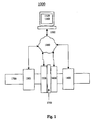
- FIG. 1 is a block diagram of an exemplary embodiment of a system 1000
- FIG. 2 is a block diagram of an exemplary embodiment of a system 2000
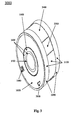
- FIG. 3 is a perspective view of an exemplary embodiment of a magnetic bearing system 3000 ;
- FIG. 4 is an end view of an exemplary embodiment of a magnetic bearing system 4000
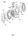
- FIG. 5 is an exploded view of an exemplary embodiment of a magnetic bearing static portion 5000
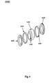
- FIG. 6 is an exploded view of an exemplary embodiment of a magnetic bearing rotating portion 6000
- FIG. 7 is an exemplary embodiment of a system 7000 illustrating section A-A of FIG. 4 ;
- FIG: 8 is an exemplary embodiment of a system 8000 illustrating section B-B of FIG. 4 ;
- FIG. 9 is an exemplary embodiment of a system 9000 illustrating section C-C of FIG. 7 ;
- FIG. 10 is an exemplary embodiment of a system 10000 illustrating section D-D of FIG. 7 ;
- FIG. 11 is an exemplary embodiment of a system 11000 illustrating section E-E of FIG. 8 ;
- FIG. 12 is a flowchart of an exemplary embodiment of a method 12000.
- adapter - a device used to effect operative compatibility between different parts of one or more pieces of an apparatus or system.
- amplifier - a device that increases strength of signals passing through it.
- annular - shaped like a ring
- apparatus an appliance or device for a particular purpose.
- an automatic light switch can turn on upon "seeing" a person in its view, without the person manually operating the light switch.
- circuit board - a thin substantially planar board to which electronic components and/or sockets therefor are mounted, coupled, and/or interconnected, typically by solder.
- Component leads and integrated circuit pins may pass through holes ("vias") in the board or they may be surface mounted, in which case no holes are required (although they may still be used to interconnect different layers of the board).
- communications port - a connector for a communications interface.
- component - a constituent element and/or part.
- connection - a physical and/or logical link and/or channel between two or more points in a system.
- a wire an optical fiber, a wireless link, and/or a virtual circuit, etc.
- control - (n) a mechanical or electronic device used to operate a machine within predetermined limits; (v) to exercise authoritative and/or dominating influence over, cause to act in a predetermined manner, direct, adjust to a requirement, and/or regulate.
- data structure an organization of a collection of data that allows the data to be manipulated effectively and/or a logical relationship among data elements that is designed to support specific data manipulation functions.
- a data structure can comprise metadata to describe the properties of the data structure. Examples of data structures can include: array, dictionary, graph, hash, heap, linked list, matrix, object, queue, ring, stack, tree, and/or vector.
- degree - a unit of angular measure equal in magnitude to 1/360 of a complete revolution in a predetermined plane.
- electromagnet - a core of magnetic material adapted to be surrounded by a coil of wire through which an electric current is passed to magnetize the core.
- gap - a space between objects.
- haptic - involving the human sense of kinesthetic movement and/or the human sense of touch.
- many potential haptic experiences are numerous sensations, body-positional differences in sensations, and time-based changes in sensations that are perceived at least partially in non-visual, non-audible, and non-olfactory manners, including the experiences of tactile touch (being touched), active touch, grasping, pressure, friction, traction, slip, stretch, force, torque, impact, puncture, vibration, motion, acceleration, jerk, pulse, orientation, limb position, gravity, texture, gap, recess, viscosity, pain, itch, moisture, temperature, thermal conductivity, and thermal capacity.
- heat - energy associated with the motion of atoms and/or molecules capable of being transmitted through solid media and fluid media by conduction, through fluid media by convection, and through fluid media and/or empty space by radiation.
- hub - a central part of a magnetic bearing adapted to be coupled to a machine rotor.
- inch - a unit of length equal to one twelfth of a foot.
- An information device any device on which resides a finite state machine capable of implementing at least a portion of a method, structure, and/or or graphical user interface described herein.
- An information device can comprise well-known communicatively coupled components, such as one or more network interfaces, one or more processors, one or more memories containing instructions, one or more input/output (I/O) devices, and/or one or more user interfaces (e.g., coupled to an I/O device) via which information can be rendered to implement one or more functions described herein.
- I/O input/output
- an information device can be any general purpose and/or special purpose computer, such as a personal computer, video game system (e.g., PlayStation, Nintendo Gameboy, X-Box, etc.), workstation, server, minicomputer, mainframe, supercomputer, computer terminal, laptop, wearable computer, and/or Personal Digital Assistant (PDA), iPod, mobile terminal, Bluetooth device, communicator, "smart" phone (such as a Treo-like device), messaging service (e.g., Blackberry) receiver, pager, facsimile, cellular telephone, a traditional telephone, telephonic device, a programmed microprocessor or microcontroller and/or peripheral integrated circuit elements, a digital signal processor, an ASIC or other integrated circuit, a hardware electronic logic circuit such as a discrete element circuit, and/or a programmable logic device such as a PLD, PLA, FPGA, or PAL, or the like, etc.
- PDA Personal Digital Assistant
- I/O device any sensory-oriented input and/or output device, such as an audio, visual, haptic, olfactory, and/or taste-oriented device, including, for example, a monitor, display, projector, overhead display, keyboard, keypad, mouse, trackball, joystick, gamepad, wheel, touchpad, touch panel, pointing device, microphone, speaker, video camera, camera, scanner, printer, haptic device, vibrator, tactile simulator, and/or tactile pad, potentially including a port to which an I/O device can be attached or connected.
- I/O device any sensory-oriented input and/or output device, such as an audio, visual, haptic, olfactory, and/or taste-oriented device, including, for example, a monitor, display, projector, overhead display, keyboard, keypad, mouse, trackball, joystick, gamepad, wheel, touchpad, touch panel, pointing device, microphone, speaker, video camera, camera, scanner, printer, haptic device, vibrator, tactile simulator, and/or tactile pad, potentially including a
- journal - portion of a shaft adapted to receive a mountable bearing.
- junction box an enclosure that houses electric wires or cables.
- machine instructions - directions adapted to cause a machine, such as an information device, to perform one or more particular activities, operations, and/or functions.
- the directions which can sometimes form an entity called a "processor”, “kernel”, “operating system”, “program”, “application”, “utility”, “subroutine”, “script”, “macro”, “file”, “project”, “module”, “library”, “class”, and/or “object”, etc., can be embodied as machine code, source code, object code, compiled code, assembled code, interpretable code, and/or executable code, etc., in hardware, firmware, and/or software.
- machine readable medium - a physical structure from which a machine, such as an information device, computer, microprocessor, and/or controller, etc., can obtain and/or store data, information, and/or instructions. Examples include memories, punch cards, and/or optically- readable forms, etc.
- magnetic - having the property of attracting iron and certain other materials by virtue of a surrounding field of force.
- magnetic bearing - a bearing that supports a load using magnetic levitation.
- memory device an apparatus capable of storing analog or digital information, such as instructions and/or data. Examples include a nonvolatile memory, volatile memory, Random Access Memory, RAM, Read Only Memory, ROM, flash memory, magnetic media, a hard disk, a floppy disk, a magnetic tape, an optical media, an optical disk, a compact disk, a CD, a digital versatile disk, a DVD, and/or a raid array, etc.
- the memory device can be coupled to a processor and/or can store instructions adapted to be executed by processor, such as according to an embodiment disclosed herein.
- method - a process, procedure, and/or collection of related activities for accomplishing something.
- modular - comprising sections that are substantially nondestructively separable.
- network - a communicatively coupled plurality of nodes, communication devices, and/or information devices.
- such devices can be linked, such as via various wireline and/or wireless media, such as cables, telephone lines, power lines, optical fibers, radio waves, and/or light beams, etc., to share resources (such as printers and/or memory devices), exchange files, and/or allow electronic communications therebetween.
- resources such as printers and/or memory devices
- a network can be and/or can utilize any of a wide variety of sub-networks and/or protocols, such as a circuit switched, public-switched, packet switched, connection-less, wireless, virtual, radio, data, telephone, twisted pair, POTS, non-POTS, DSL, cellular, telecommunications, video distribution, cable, terrestrial, microwave, broadcast, satellite, broadband, corporate, global, national, regional, wide area, backbone, packet-switched TCP/IP, IEEE 802.03, Ethernet, Fast Ethernet, Token Ring, local area, wide area, IP, public Internet, intranet, private, ATM, Ultra Wide Band (UWB), Wi-Fi, BlueTooth, Airport, IEEE 802.11, IEEE 802.11a, IEEE 802.11b, IEEE 802.11g, X-10, electrical power, multi-domain, CAN, Modbus, serial protocol, and/or multi-zone sub-network and/or protocol, one or more Internet service providers, and/or one or more information devices, such as a switch, router, and/or gateway not directly connected
- network interface any physical and/or logical device, system, and/or process capable of coupling an information device to a network.
- Exemplary network interfaces comprise a telephone, cellular phone, cellular modem, telephone data modem, fax modem, wireless transceiver, Ethernet card, cable modem, digital subscriber line interface, bridge, hub, router, or other similar device, software to manage such a device, and/or software to provide a function of such a device.
- packet - a generic term for a bundle of data organized in a specific way for transmission, such as within and/or across a network, such as a digital packet-switching network, and comprising the data to be transmitted and certain control information, such as a destination address.
- pair - a quantity of two of something.
- portion - a part, component, section, percentage, ratio, and/or quantity that is less than a larger whole. Can be visually, physically, and/or virtually distinguishable and/or non-distinguishable.
- power - energy a measure of energy and/or work, and/or a rate at which work is done, expressed as the amount of work per unit time and commonly measured in units such as watt and horsepower.
- processor - a hardware, firmware, and/or software machine and/or virtual machine comprising a set of machine-readable instructions adaptable to perform a specific task.
- a processor can utilize mechanical, pneumatic, hydraulic, electrical, magnetic, optical, informational, chemical, and/or biological principles, mechanisms, signals, and/or inputs to perform the task(s).
- a processor can act upon information by manipulating, analyzing, modifying, and/or converting it, transmitting the information for use by an executable procedure and/or an information device, and/or routing the information to an output device.
- a processor can function as a central processing unit, local controller, remote controller, parallel controller, and/or distributed controller, etc.
- the processor can be a general-purpose device, such as a microcontroller and/or a microprocessor, such the Pentium IV series of microprocessor manufactured by the Intel Corporation of Santa Clara, California.
- the processor can be dedicated purpose device, such as an Application Specific Integrated Circuit (ASIC) or a Field Programmable Gate Array (FPGA) that has been designed to implement in its hardware and/or firmware at least a part of an embodiment disclosed herein.
- a processor can reside on and use the capabilities of a controller.
- pulse width modulated - encoded via pulse width modulation pulse width modulation
- radial - relating to a bearing adapted to restrain displacement substantially radial to a center of rotation and/or perpendicular to an axis of rotation.
- ring - a substantially toroidal object that can be imagined as having been generated by rotating a closed loop (e.g., ellipse, circle, irregular curve, polygon, etc.) about a fixed line external to the loop:
- a closed loop e.g., ellipse, circle, irregular curve, polygon, etc.
- sensor - a device adapted to automatically sense, perceive, detect, and/or measure a physical property (e.g., pressure, temperature, flow, mass, heat, light, sound, humidity, proximity, position, velocity, vibration, loudness, voltage, current, capacitance, resistance, inductance, and/or electromagnetic radiation, etc.) and convert that physical quantity into a signal.
- a physical property e.g., pressure, temperature, flow, mass, heat, light, sound, humidity, proximity, position, velocity, vibration, loudness, voltage, current, capacitance, resistance, inductance, and/or electromagnetic radiation, etc.
- Examples include proximity switches, stain gages, photo sensors, thermocouples, level indicating devices, speed sensors, accelerometers, electrical voltage indicators, electrical current indicators, on/off indicators, and/or flowmeters, etc.
- signal - information such as machine instructions for activities and/or one or more letters, words, characters, symbols, signal flags, visual displays, and/or special sounds, etc. having prearranged meaning, encoded as automatically detectable variations in a physical variable, such as a pneumatic, hydraulic, acoustic, fluidic, mechanical, electrical, magnetic, optical, chemical, and/or biological variable, such as power, energy, pressure, flowrate, viscosity, density, torque, impact, force, voltage, current, resistance, magnetomotive force, magnetic field intensity, magnetic field flux, magnetic flux density, reluctance, permeability, index of refraction, optical wavelength, polarization, reflectance, transmittance, phase shift, concentration, and/or temperature, etc.
- a physical variable such as a pneumatic, hydraulic, acoustic, fluidic, mechanical, electrical, magnetic, optical, chemical, and/or biological variable, such as power, energy, pressure, flowrate, viscosity, density, torque, impact, force, voltage, current, resistance, magnetomotiv
- a signal and/or the information encoded therein can be synchronous, asychronous, hard real-time, soft real-time, non-real time, continuously generated, continuously varying, analog, discretely generated, discretely varying, quantized, digital, broadcast, multicast, unicast, transmitted, conveyed, received, continuously measured, discretely measured, processed, encoded, encrypted, multiplexed, modulated, spread, de-spread, demodulated, detected, de-multiplexed, decrypted, and/or decoded, etc.
- source - an original and/or intermediate transmitter of traffic and/or a related group of such transmitters and/or a point at which something originates, springs into being, and/or from which it derives and/or is obtained.
- stator - a stationary part in or about which another part (the rotor) revolves.
- system - a collection of mechanisms, devices, data, and/or instructions, the collection designed to perform one or more specific functions.
- the surface adapted to separate a static portion of the magnetic bearing assembly from a portion of the magnetic bearing assembly that is adapted to rotate when magnetic fields of the magnetic bearing assembly are insufficient for rotor levitation.
- convey e.g., force, energy, and/or information
- a user interface can include at least one of textual, graphical, audio, video, animation, and/or haptic elements.
- a textual element can be provided, for example, by a printer, monitor, display, projector, etc.
- a graphical element can be provided, for example, via a monitor, display, projector, and/or visual indication device, such as a light, flag, beacon, etc.
- An audio, element can be provided, for example, via a speaker, microphone, and/or other sound generating and/or receiving device.
- a video element or animation element can be provided, for example, via a monitor, display, projector, and/or other visual device.
- a haptic element can be provided, for example, via a very low frequency speaker, vibrator, tactile stimulator, tactile pad, simulator, keyboard, keypad, mouse, trackball, joystick, gamepad, wheel, touchpad, touch panel, pointing device, and/or other haptic device, etc.
- a user interface can include one or more textual elements such as, for example, one or more letters, number, symbols, etc.
- a user interface can include one or more graphical elements such as, for example, an image, photograph, drawing, icon, window, title bar, panel, sheet, tab, drawer, matrix, table, form, calendar, outline view, frame, dialog box, static text, text box, list, pick list, pop-up list, pull-down list, menu, tool bar, dock, check box, radio button, hyperlink, browser, button, control, palette, preview panel, color wheel, dial, slider, scroll bar, cursor, status bar, stepper, and/or progress indicator, etc.
- a textual and/or graphical element can be used for selecting, programming, adjusting, changing, specifying, etc.
- a user interface can include one or more audio elements such as, for example, a volume control, pitch control, speed control, voice selector, and/or one or more elements for controlling audio play, speed, pause, fast forward, reverse, etc.
- a user interface can include one or more video elements such as, for example, elements controlling video play, speed, pause, fast forward, reverse, zoom-in, zoom-out, rotate, and/or tilt, etc.
- a user interface can include one or more animation elements such as, for example, elements controlling animation play, pause, fast forward, reverse, zoom-in, zoom-out, rotate, tilt, color, intensity, speed, frequency, appearance, etc.
- a user interface can include one or more haptic elements such as, for example, elements utilizing tactile stimulus, force, pressure, vibration, motion, displacement, temperature, etc.
- volume - a disk drive and/or virtual disk drive.
- wedge - an object comprising two substantially planar, substantially radial faces that are separated by an acute angle and are bounded by a substantially arcuate and/or planar face, and comprising an opposing pair of substantially parallel, substantially sector-shaped faces that are substantially perpendicular to the two substantially planar, substantially radial faces. when - at a time.
- US Patent 6590366 allegedly describes "a control system for electromechanical arrangements having open-top instability". This document discloses systems comprising all the features of the preambles of claims 1 or 19. The invention corresponds to a system comprising all the features of claim 1 or claim 19.
- the invention can provide various advantages.
- the invention can comprise a relatively compact magnetic bearing adapted for use in machinery with rotating shafts.
- Magnetic bearings can be used to support and position rotating machinery for applications in which one or more of the following specifications is present:
- relatively high rotational speeds e.g., between approximately 3,600 and approximately 100,000 rpm
- Certain exemplary magnetic bearing systems can comprise electromagnets, sensors, and/or electronic controls. Electrical connections between the electronic controls and the electromagnets can carry electrical currents related to operation of the magnetic bearing.
- a radial bearing can be adapted to support a rotating shaft along lateral directions.
- the radial bearing can comprise three or more electromagnets and/or sensors.
- a thrust bearing can be adapted to restrain motion of the rotating shaft along a longitudinal (axial) direction.
- the thrust bearing can comprise two or more electromagnets and two or more sensors.
- a five-axis system can comprise two radial bearings and one or more thrust bearings, which collectively can comprise approximately ten electromagnets and/or approximately ten sensors.
- Electrical energy for the magnetic bearing can be transferred from a source of electrical energy to amplifiers and/or electromagnets of the magnetic bearing.
- the amplifiers can be continuous-type amplifiers and/or switch-type amplifiers such as pulse-width modulated (PWM) amplifiers.
- PWM pulse-width modulated
- each electromagnet in the magnetic bearing can behave as a large inductor in series with a small resistance, reactive power flowing to each electromagnet might be high, but actual net energy that flows to the magnetic bearings might be relatively small, even for relatively large current levels within in the magnetic bearing.
- a relatively small amount power might be dissipated in amplifiers and electromagnets, a current flowing between the source of electrical energy and the amplifier for each electromagnet can be a small fraction of a current flow in an exemplary electromagnet.
- an electrical current flow in an electromagnet can be approximately ten times higher than a current flow to an exemplary amplifier.
- certain exemplary embodiments can keep amplifiers and electromagnets in relatively close proximity.
- the magnetic bearing can comprise electronic controls.
- Amplifiers can be located in relatively close proximity to electromagnets.
- leads between the amplifiers and the electromagnets can be relatively short and within the magnetic bearing so an amount of EMI produced is relatively low.
- FIG. 1 is a block diagram of an exemplary embodiment of a system 1000, which can comprise a shaft 1700.
- a displacement of shaft 1700 can be radially restrained via a first magnetic bearing 1300 and/or a second magnetic bearing 1400.
- Each of first magnetic bearing 1300 and/or second magnetic bearing 1400 can comprise a rotating portion and a static portion.
- Shaft 1700 can comprise a disk portion 1750.
- An axial displacement of shaft 1700 can be restrained via first thrust magnetic bearing 1500 and/or second thrust magnetic bearing 1600 acting upon disk portion 1750.
- Each of first magnetic bearing 1300, second magnetic bearing 1400, first thrust magnetic bearing 1500, and/or second thrust magnetic bearing 1600 can be externally monitored and/or controlled via a control program 1160 executing on an information device 1100. Signals to each of first magnetic bearing 1300, second magnetic bearing 1400, first thrust magnetic bearing 1500, and/or second thrust magnetic bearing 1600 can be transmitted via a network 1200.
- Information device 1100 can comprise a user interface 1120, which can be adapted to render information related to shaft 1700, first magnetic bearing 1300, second magnetic bearing 1400, first thrust magnetic bearing 1500, and/or second thrust magnetic bearing 1600.
- FIG. 2 is a block diagram of an exemplary embodiment of a system 2000, which can comprise a junction box 2800, which can be adapted to electrically couple a first radial magnetic bearing static portion 2200 to an energy source 2900.
- Energy source 2900 can be a direct current (DC) energy source adapted to provide electrical energy via a positive lead and negative lead.
- System 2000 can comprise a shaft 2100. Shaft 2100 can be supported and/or restrained in motion relative to a static structure 2400 via first radial magnetic bearing static portion 2200, second radial magnetic bearing static portion 2300, first thrust magnetic bearing static portion 2160 and/or second thrust magnetic bearing static portion 2180.
- First magnetic bearing static portion 2200 can be associated with a corresponding first magnetic bearing rotating portion 2250.
- second magnetic bearing static portion 2300 can be associated with a corresponding second magnetic bearing rotating portion 2350. Electrical energy can be provided to first radial magnetic bearing static portion 2200 via a first pair of electrical conductors 2500. Electrical energy can be provided to first thrust magnetic bearing static portion 2160 and/or second thrust magnetic bearing static portion 2180 via a second pair of electrical conductors 2600. Similarly, electrical energy can be provided to second radial magnetic bearing static portion 2300 via a third pair of electrical conductors 2700.
- First thrust magnetic bearing static portion 2160 and/or second thrust magnetic bearing static portion 2180 can be adapted to restrain shaft 2100 via a disk portion 2150.
- First thrust magnetic bearing static portion 2160 and/or second thrust magnetic bearing static portion 2180 can comprise two or more electromagnets.
- an air gap 2120 between first magnetic bearing rotating portion 2250 and first magnetic bearing static portion 2200 can be less, in inches, than approximately 0.001, 0.003, 0.006, 0.010, 0.011, 0.014, 0.019, 0.020, 0.03, 0.034, 0.037, and/or 0.040, and/or any value or subrange therebetween.
- an electronic control which can be adapted for sensing, processing, and/or amplification.
- the electronic control can be packaged within a stator structure of a magnetic bearing static portion, such as first magnetic bearing static portion 2200;
- first magnetic bearing static portion 2200 such as first magnetic bearing static portion 2200, second radial magnetic bearing static portion 2300, first thrust magnetic bearing static portion 2160 and/or second thrust magnetic bearing static portion 2180 without the need for an external electronic controller;
- first radial magnetic bearing static portion 2200, second radial magnetic bearing static portion 2300, first thrust magnetic bearing static portion 2160 and/or second thrust magnetic bearing static portion 2180 can be associated with one or more circuit boards of an annular shape (such as first annular circuit board 5300 and second annular circuit board 5900 of FIG. 5 ) that can be packaged on either side of electromagnets;
- first radial magnetic bearing static portion 2200, second radial magnetic bearing static portion 2300, first thrust magnetic bearing static portion 2160 and/or second thrust magnetic bearing static portion 2180 can comprise independent electromagnets shaped in an E shape (such as illustrated by electromagnet 5700 of FIG. 5 ) with one coil per electromagnet and no back iron;
- first radial magnetic bearing static portion 2200, second radial magnetic bearing static portion 2300, first thrust magnetic bearing static portion 2160 and/or second thrust magnetic bearing static portion 2180 can comprise electronic circuit boards and wiring in wedge-shaped volumes (such as wedge volumes 5600 of FIG. 5 ) between electromagnets (such as electromagnet 5700 of FIG. 5 );
- first radial magnetic bearing static portion 2200, second radial magnetic bearing static portion 2300, first thrust magnetic bearing static portion 2160 and/or second thrust magnetic bearing static portion 2180 can comprise relatively small sensors (such as sensors 5500 of FIG. 5 ) positioned on both sides of electromagnets (such as electromagnet 5700 of FIG. 5 );
- first radial magnetic bearing static portion 2200, second radial magnetic bearing static portion 2300, first thrust magnetic bearing static portion 2160 and/or second thrust magnetic bearing static portion 2180 can comprise sensors between electromagnets (such as electromagnet 5700 of FIG. 5 ) at angular positions offset from centers of electromagnets so that the sensors (such as sensors 5500 of FIG. 5 ) can be packaged between end winding (such as coil 5780 of FIG. 5 ) of the electromagnets; and/or
- touchdown surfaces (such as touchdown first touchdown ring 5100 and/or second touchdown ring 5950 of FIG. 5 ) on either side of first radial magnetic bearing static portion 2200 and/or second radial magnetic bearing static portion 2300.
- FIG. 3 is a perspective view of an exemplary embodiment of a magnetic bearing system 3000, which illustrates an exemplary radial magnetic bearing static portion 3100 and a radial magnetic rotating portion 3600 when both are assembled.
- Radial magnetic rotating portion 3600 can be mounted on the outside diameter of a rotating shaft of a machine and rotates with the shaft.
- Radial magnetic bearing static portion 3100 which can comprise electromagnets and electronics, can substantially surround radial magnetic rotating portion 3600.
- An inner diameter of radial magnetic bearing static portion 3100 can be slightly larger than an outside diameter of radial magnetic rotating portion 3600 so that a radial air gap exists between radial magnetic rotating portion 3600 and radial magnetic bearing static portion 3100.
- radial magnetic bearing static portion 3100 can actively position radial magnetic rotating portion 3600 such that radial magnetic rotating portion 3600 remains substantially concentric to radial magnetic bearing static portion 3100, thereby substantially eliminating mechanical contact.
- Radial magnetic bearing static portion 3100 can comprise:
- stator lamination stacks 3400 a plurality of stator lamination stacks 3400;
- Radial magnetic bearing rotating portion 3600 can comprise:
- System 3000 can be packaged in radial magnetic bearing static portion 3100.
- System 3000 can comprise an electrical connection 3950, which can be adapted to receive electrical energy from an electrical energy source.
- System 3000 can comprise a communications port 3900, which can be communicatively coupled to a network.
- FIG. 4 is an end view of an exemplary embodiment of a magnetic bearing system 4000, which can comprise:
- an electrical connection 4600 which can be adapted to receive electrical energy from an electrical energy source;
- a communications port 4500 which can be communicatively coupled to a network.
- FIG. 5 is an exploded view of an exemplary embodiment of a magnetic bearing static portion 5000, which can comprise a plurality of electromagnets 5700, such as three or more electromagnets 5700.
- Each electromagnet 5700 can be comprised by an electromagnet sector 5750.
- Each electromagnet 5700 can comprise a coil 5780.
- Magnetic bearing static portion 5000 can comprise a first support plate 5400 and/or a second support plate 5800, each of which can be adapted to support and/or restrain motion of electromagnet sectors 5750, a plurality of wedge volumes 5600, and/or a plurality of position sensors 5500.
- Magnetic bearing static portion 5000 can comprise a plurality of pulse width modulated amplifiers, such as three or more pulse width modulated amplifiers, housed within a respective corresponding wedge volume of plurality of wedge volumes 5600.
- Each pulse width modulated amplifiers can be adapted to provide electrical energy to a corresponding electromagnet of plurality of electromagnets 5700.
- Each of the plurality of wedge volumes 5600 can be radially disposed between a corresponding pair of plurality of electromagnets 5700.
- One or more of the plurality of wedge volumes 5600 can be adapted to pass electrical signals from plurality of position sensors 5500 to at least one of a first annular circuit board 5300 and a second annular circuit board 5900.
- electromagnets there are four electromagnets, each consisting of a stack of bonded E-laminations with a coil wound around the center leg of an "E" shaped electromagnet.
- each of plurality of electromagnets 5700 is individually secured between first support plate 5400 and second support plate 5800 without a continuous back iron between plurality of electromagnets 5700.
- Each electromagnet 5700 can be comprised by a modular electromagnet sector 5750. Each electromagnet 5700 can be associated with a corresponding pulse width modulated amplifier. Each pulse width modulated amplifier can be adapted to provide electrical energy to a corresponding electromagnet 5700. A corresponding wedge volume 5600 can comprise each of the pulse width modulated amplifiers. Each wedge volume 5600 can be radially disposed between a corresponding pair of the electromagnets 5700.
- Support plate 5400 can be adapted to transfer greater than fifty percent of heat provided from an axial face of magnetic bearing static portion 5000.
- the axial face of magnetic bearing static portion 5000 can be at least partially defined by touchdown ring 5100.
- the heat can be generated by components such as:
- the pulse width modulated amplifiers comprised by and/or contained in wedge volumes 5600, etc.
- First annular circuit board 5300 can be adapted to accept a communicative connection from a network at communication connector 5200.
- Second annular circuit board 5900 can be adapted to provide electrical energy, communicative signaling, and/or control signaling to the plurality pulse width modulated amplifiers.
- First annular circuit board 5300 can be electrically coupled and/or communicatively coupled to second annular circuit board 5900.
- Plurality of position sensors 5500 can be adapted to detect a radial position of a magnetic bearing rotating portion corresponding to magnetic bearing static portion 5000.
- Each of plurality of position sensors 5500 can be located between a corresponding pair of plurality of electromagnets 5700. As such, each of plurality of position sensors 5500 fits between a corresponding pair of coils of plurality of electromagnets 5700.
- plurality of sensors 5500 can comprise eight sensors, which can each be offset by approximately 45 degrees.
- Magnetic bearing static portion 5000 can comprise a first touchdown ring 5100 and/or a second touchdown ring 5950, each of which can be adapted to separate static portion 5000 from the corresponding magnetic bearing rotating portion when no electrical energy is applied to the radial magnetic bearing.
- a radial gap between the inner diameter of first touchdown ring 5100 and/or second touchdown ring 5950 and corresponding touchdown journals comprised by a rotating portion of the magnetic bearing can be approximately one-half of a radial gap between.plurality of electromagnets 5700 and the rotating portion of the magnetic bearing.
- the rotating portion of the magnetic bearing can be supported at an inner diameter of first touchdown ring 5100 and/or second touchdown ring 5950 without contact between the magnetic iron in magnetic bearing static portion 5000 and the rotating portion of the magnetic bearing. This reduces potential damage to the magnetic bearing and/or an associated machine when the magnetic bearing is not operating. Because touchdown surfaces are included on both ends of magnetic bearing static portion 5000, the magnetic iron is protected from contact along an entire length of an associated lamination stack.
- FIG. 6 is an exploded view of an exemplary embodiment of a magnetic bearing rotating portion 6000, which can comprise a series of components mounted on an outer diameter of a hollow hub 6100.
- Hub 6100 can be mounted on a shaft of a machine (not illustrated).
- a stack of rotor laminations 6200 can be mounted in a central region of hub 6100.
- Rotor laminations 6200 can be adapted to complete a magnetic flux path of electromagnets comprised by a magnetic bearing static portion, thereby producing a radial force associated with the magnetic bearing.
- first sensor target ring 6300 and second sensor target ring 6500 which can be surfaces detected by a plurality of sensors comprised by the magnetic bearing static portion.
- Magnetic bearing rotating portion 6000 can comprise a first touchdown journal 6400 and/or a second touchdown journal 6600, which can be adapted to contact a inner diameter of a corresponding pair of touchdown rings when the magnetic bearing is not energized.
- FIG. 7 is an exemplary embodiment of a system 7000 illustrating section A-A of FIG. 4 , which is a sectional view of a cut made through a central region of electromagnets.
- System 7000 can comprise:
- annular circuit board 7800 etc.
- FIG. 8 is an exemplary embodiment of a system 8000 illustrating section B-B of FIG. 4 , which can be a sectional view of a cut made through a region comprising sensors of an exemplary embodiment
- System 8000 can comprise:
- FIG. 9 is an exemplary embodiment of a system 9000 illustrating section C-C of FIG. 7 , which can be a cross section at the axial plane of the electromagnets.
- System 9000 can comprise:
- FIG. 10 is an exemplary embodiment of a system 10000 illustrating section D-D of FIG. 7 , which is a cross section at an axial plane of position sensors.
- System 10000 can comprise:
- FIG. 11 is an exemplary embodiment of a system 11000 illustrating section E-E of FIG. 8 , which is a cross section at an axial plane of touchdown surfaces.
- FIG. 11 illustrates an exemplary embodiment of a sensor fitting between end windings of electromagnets.
- System 11000 can comprise:
- FIG. 12 is a flowchart of an exemplary embodiment of a method 12000.
- electromagnets can be obtained.
- an E-shaped electromagnet such as electromagnet 5700 of FIG. 5 can be obtained.
- coils can be obtained, which can be adapted for placement on the electromagnets.
- a coil such as coil 5780 of FIG. 5 can be obtained.
- electronics can be obtained.
- a plurality of electronic circuits adapted to provide pulse width modulated signals to the electromagnets can be obtained.
- the electronic circuits can be adapted for installation and/or placement in one or more wedge volumes of a static portion of a magnetic bearing.
- a plurality of sensors can be obtained.
- the plurality of sensors can be adapted to be installed between a corresponding pair of electromagnets.
- the plurality of sensors can be adapted to detect a radial position of a rotating portion of the magnetic bearing relative to the static portion of the magnetic bearing.
- support plates can be obtained.
- the support plates can be adapted to, in certain operative embodiments, hold the plurality of electromagnets in a substantially fixed position relative to the plurality of wedge volumes.
- a plurality of annular circuit boards can be obtained. At least one of the plurality of annular circuit boards can be communicatively coupled to the plurality of electronic circuits. At least one of the plurality of annular circuit boards can be adapted to provide electrical energy to the electronic circuits.
- touchdown rings can be obtained.
- the touchdown rings can be adapted to rest on corresponding touchdown journals of a magnetic bearing when the magnetic bearing is not energized.
- the static portion of the magnetic portion of the magnetic bearing can be assembled.
- the static portion of the magnetic bearing can comprise:
- a rotating portion of the magnetic bearing can be assembled.
- the rotating portion of the magnetic bearing can comprise:
- any elements can be integrated, segregated, and/or duplicated;
- any activity can be repeated, performed by multiple entities, and/or performed in multiple jurisdictions;
- any activity or element can be specifically excluded, the sequence of activities can vary, and/or the interrelationship of elements can vary.
Landscapes
- Engineering & Computer Science (AREA)
- General Engineering & Computer Science (AREA)
- Mechanical Engineering (AREA)
- Power Engineering (AREA)
- Magnetic Bearings And Hydrostatic Bearings (AREA)
- Connection Of Motors, Electrical Generators, Mechanical Devices, And The Like (AREA)
Claims (20)
- System, aufweisend:einen Stator, aufweisend:einen ersten statischen Abschnitt (2200) eines radialen magnetischen Lagers (1300), aufweisend:drei oder mehr Elektromagneten (5700), wobei jeder Elektromagnet in einem modularen Elektromagnetsektor enthalten ist; unddrei oder mehr pulsweitenmodulierte Verstärker, die jeweils dazu geeignet sind,einem zugeordneten Elektromagneten (5700) der drei oder mehr Elektromagneten (5700) elektrische Energie zuzuführen,dadurch gekennzeichnet, dassjeder der drei oder mehr pulsweitenmodulierten Verstärker in einem entsprechenden Keilvolumen (5600) enthalten ist, wobei jedes Keilvolumen radial zwischen einem Paar der drei oder mehr Elektromagneten (5700) angeordnet ist.
- System nach Anspruch 1, ferner aufweisend:einen Rotor, aufweisend:einen Drehabschnitt (2250) des radialen magnetischen Lagers, aufweisend:eine Nabe (3700);eine Vielzahl von Schichtungen;einen Sensorreferenzring;einen ersten Aufsetzlagerzapfen (3500); undeinen zweiten Aufsetzlagerzapfen; undwobei der statische Abschnitt des radialen magnetischen Lagers ferner aufweist:eine erste Trägerplatte (5400), die dazu geeignet ist, die Elektromagnetsektoren (5750) zu tragen;eine zweite Trägerplatte (5800), die dazu geeignet ist, die Elektromagnetsektoren zu tragen;eine erste ringförmige Leiterplatte (5300), die dazu geeignet ist, eine kommunizierende Verbindung aus einem Netzwerk anzunehmen;eine zweite ringförmige Leiterplatte (5900), die dazu geeignet ist, den drei odermehr pulsweitenmodulierten Verstärkern Steuermeldungen zuzuführen;eine Vielzahl von Lagesensoren (5500), die dazu geeignet sind, eine radiale Lage des Rotors zu erkennen, wobei sich jeder der Vielzahl von Lagesensoren zwischen einem Paar von drei oder mehr Elektromagneten (5700) befindet;einen Aufsetzring (5100), der dazu geeignet ist, den Rotor von dem Stator zu trennen, wenn keine elektrische Energie an das radiale magnetische Lager angelegt ist; undwobei der Stator ferner einen statischen Abschnitt (2160) eines magnetischen Drucklagers (1500) aufweist, aufweisend:zwei oder mehr Elektromagneten (5700);zwei oder mehr pulsweitenmodulierte Verstärker, die jeweils dazu geeignet sind, einem zugeordneten Elektromagneten der zwei oder mehr Elektromagneten elektrische Energie zuzuführen, wobei jeder der zwei odermehr pulsweitenmodulierten Verstärker in einem entsprechenden Keilvolumen (5600) enthalten ist, wobei jedes Keilvolumen radial zwischen einem entsprechenden Paar der zwei oder mehr Elektromagneten angeordnet ist;eine erste ringförmige Leiterplatte (5300), die dazu geeignet ist, eine kommunizierende Verbindung aus einem Netzwerk anzunehmen; undeine zweite ringförmige Leiterplatte (5900), die dazu geeignet ist, den zwei odermehr pulsweitenmodulierten Verstärkern Steuermeldungen zuzuführen.
- System nach Anspruch 1, ferner aufweisend:ein Verzweigungsstück (2800), das dazu geeignet ist, den ersten statischen Abschnitt (2200) des radialen magnetischen Lagers elektrisch an eine Energiequelle (2900) zu koppeln.
- System nach Anspruch 1, ferner aufweisend:einen zweiten statischen Abschnitt (2300) des radialen magnetischen Lagers.
- System nach Anspruch 1, ferner aufweisend:einen ersten Drehabschnitt (2250) des radialen magnetischen Lagers, der dazu geeignet ist, an den ersten statischen Abschnitt (2200) des radialen magnetischen Lagers magnetisch gekoppelt zu werden.
- System nach Anspruch 1, ferner aufweisend:einen ersten Drehabschnitt (2250) des radialen magnetischen Lagers, der dazu geeignet ist, mit dem ersten statischen Abschnitt des radialen magnetischen Lagers magnetisch gekoppelt zu werden, wobei der erste Drehabschnitt des radialen magnetischen Lagers aufweist:eine Nabe (3700);eine Vielzahl von Schichtungen;einen Sensorreferenzring;einen ersten Aufsetzlagerzapfen (3500), undeinen zweiten Aufsetzlagerzapfen.
- System nach Anspruch 1, ferner aufweisend:eine Trägerplatte, die dazu geeignet ist, die drei oder mehr Elektromagneten zu tragen.
- System nach Anspruch 1, ferner aufweisend:eine erste Trägerplatte (3200), die dazu geeignet ist, die drei oder mehr Elektromagneten zu tragen; undeine zweite Trägerplatte (3200), die dazu geeignet ist, die drei oder mehr Elektromagneten zu tragen.
- System nach Anspruch 1, ferner aufweisend:eine ringförmige Leiterplatte (5300), die dazu geeignet ist, eine kommunizierende Verbindung aus einem Netzwerk anzunehmen.
- System nach Anspruch 1, ferner aufweisend:eine ringförmige Leiterplatte (5300), die dazu geeignet ist, den drei oder mehr pulsweitenmodulierten Verstärkern Steuermeldungen zuzuführen.
- System nach Anspruch 1, ferner aufweisend:eine erste ringförmige Leiterplatte (5300), die dazu geeignet ist, eine kommunizierende Verbindung aus einem Netzwerk anzunehmen; undeine zweite ringförmige Leiterplatte (5900), die dazu geeignet ist, den drei oder mehr pulsweitenmodulierten Verstärkern Steuermeldungen zuzuführen.
- System nach Anspruch 1, ferner aufweisend:eine ringförmige Leiterplatte (5300), die dazu geeignet ist, eine kommunizierende Verbindung aus einem Netzwerk anzunehmen, wobei die ringförmige Leiterplatte einen Kommunikationsanschluss (3900) aufweist.
- System nach Anspruch 1, ferner aufweisend:eine Vielzahl von Lagesensoren (5500), die dazu geeignet sind, eine radiale Lage eines dem Stator zugeordneten Rotors zu erkennen, wobei sich jeder der Vielzahl von Lagesensoren zwischen einem entsprechenden Paar der drei oder mehr Elektromagneten (5700) befindet.
- System nach Anspruch 1, ferner aufweisend:eine Vielzahl von Lagesensoren (5500), die dazu geeignet sind, eine radiale Lage eines dem Stator zugeordneten Rotors zu erkennen, wobei sich jeder der Vielzahl von Lagesensoren zwischen einem entsprechenden Paar der drei oder mehr Elektromagneten (5700) befindet, wobei die Vielzahl von Sensoren acht Sensoren aufweist, die jeweils um etwa 45 Grad versetzt sind.
- System nach Anspruch 1, ferner aufweisend:einen Aufsetzring (5100), der dazu geeignet ist, einen Rotor von dem Stator zu trennen, wenn an das erste radiale magnetische Lager (1300) kein Strom angelegt ist.
- System nach Anspruch 1, ferner aufweisend:einen statischen Abschnitt (2160) eines magnetischen Drucklagers, aufweisend zwei oder mehr Elektromagneten (5700).
- System nach Anspruch 1, wobei ein Luftspalt zwischen einem Drehabschnitt eines magnetischen Lagers, das den ersten statischen Abschnitt des radialen magnetischen Lagers aufweist, und dem statischen Abschnitt (2200) des magnetischen Lagers weniger als 0,020 Inch beträgt.
- System nach Anspruch 1, wobei ein zwischen einem ersten Aufsetzring (5100) eines magnetischen Lagers, das den ersten statischen Abschnitt (2200) des radialen magnetischen Lagers aufweist, und einem Drehabschnitt des magnetischen Lagers definierter Spalt weniger als 0,010 Inch beträgt.
- System, aufweisend:einen Stator, aufweisend:einen statischen Abschnitt (2160) eines magnetischen Drucklagers (1500), aufweisend:zwei oder mehr Elektromagneten (5700), wobei jeder Elektromagnet (5700) in einem modularen Elektromagnetsektor (5750) enthalten ist; undzwei oder mehr pulsweitenmodulierte Verstärker, die jeweils dazu geeignet sind, einem zugeordneten Elektromagneten (5700) der zwei oder mehr Elektromagneten (5700) elektrische Energie zuzuführen, dadurch gekennzeichnet, dass jeder der zwei oder mehr pulsweitenmodulierten Verstärker in einem entsprechenden Keilvolumen (5600) enthalten ist, wobei jedes Keilvolumen (5600) radial zwischen einem entsprechenden Paar der zwei oder mehr Elektromagneten (5700) angeordnet ist.
- System nach Anspruch 19, wobei der Stator aufweist:eine Trägerplatte (5400), die dazu geeignet ist, mehr als fünfzig Prozent der von einer axialen Fläche des Stators zugeführten Wärme zu übertragen, wobei die Wärme von Komponenten des Stators erzeugt wird.
Applications Claiming Priority (2)
| Application Number | Priority Date | Filing Date | Title |
|---|---|---|---|
| US11/525,398 US7471022B2 (en) | 2006-09-22 | 2006-09-22 | Magnetic bearing |
| PCT/US2007/014090 WO2008039256A2 (en) | 2006-09-22 | 2007-06-14 | Magnetic bearing |
Publications (3)
| Publication Number | Publication Date |
|---|---|
| EP2064802A2 EP2064802A2 (de) | 2009-06-03 |
| EP2064802A4 EP2064802A4 (de) | 2011-03-09 |
| EP2064802B1 true EP2064802B1 (de) | 2012-08-15 |
Family
ID=39224180
Family Applications (1)
| Application Number | Title | Priority Date | Filing Date |
|---|---|---|---|
| EP07809594A Active EP2064802B1 (de) | 2006-09-22 | 2007-06-14 | Magnetisches lager |
Country Status (16)
| Country | Link |
|---|---|
| US (2) | US7471022B2 (de) |
| EP (1) | EP2064802B1 (de) |
| JP (2) | JP5174821B2 (de) |
| KR (1) | KR101039162B1 (de) |
| CN (1) | CN101536289B (de) |
| AU (1) | AU2007300736B2 (de) |
| BR (1) | BRPI0715240A2 (de) |
| CA (1) | CA2664086C (de) |
| CO (1) | CO6170396A2 (de) |
| IL (1) | IL197741A (de) |
| MX (1) | MX2009003111A (de) |
| MY (1) | MY143857A (de) |
| NO (1) | NO20091558L (de) |
| RU (1) | RU2401497C1 (de) |
| WO (1) | WO2008039256A2 (de) |
| ZA (1) | ZA200902471B (de) |
Families Citing this family (61)
| Publication number | Priority date | Publication date | Assignee | Title |
|---|---|---|---|---|
| US8460243B2 (en) | 2003-06-10 | 2013-06-11 | Abbott Diabetes Care Inc. | Glucose measuring module and insulin pump combination |
| US7722536B2 (en) | 2003-07-15 | 2010-05-25 | Abbott Diabetes Care Inc. | Glucose measuring device integrated into a holster for a personal area network device |
| WO2005119524A2 (en) | 2004-06-04 | 2005-12-15 | Therasense, Inc. | Diabetes care host-client architecture and data management system |
| US9351669B2 (en) | 2009-09-30 | 2016-05-31 | Abbott Diabetes Care Inc. | Interconnect for on-body analyte monitoring device |
| US7898523B1 (en) * | 2006-06-09 | 2011-03-01 | Ronald Van Meter | Device for controlling on-screen pointer |
| US7471022B2 (en) * | 2006-09-22 | 2008-12-30 | Sortore Christopher K | Magnetic bearing |
| JP4408443B2 (ja) * | 2007-08-01 | 2010-02-03 | 株式会社日立製作所 | 回転電機 |
| JP5172302B2 (ja) * | 2007-12-06 | 2013-03-27 | 京セラ株式会社 | 基地局装置の変調方式選択方法およびそれを利用した基地局装置 |
| KR20110014590A (ko) | 2008-04-17 | 2011-02-11 | 신크로니, 아이엔씨. | 저-손실 금속 회전자를 구비한 고속 영구자석 모터 및 발전기 |
| CA2721818A1 (en) * | 2008-04-18 | 2009-11-19 | Synchrony, Inc. | Magnetic thrust bearing with integrated electronics |
| EP2274819B1 (de) * | 2008-04-30 | 2017-04-05 | Levitronix GmbH | Rotationsmaschine, verfahren zur bestimmung einer verkippung eines rotors einer rotationsmaschine, sowie bearbeitungsanlage |
| US8317651B2 (en) | 2008-05-07 | 2012-11-27 | Fallbrook Intellectual Property Company Llc | Assemblies and methods for clamping force generation |
| AT509298B1 (de) * | 2008-06-19 | 2012-01-15 | Univ Wien Tech | Aktorsystem |
| JP5273526B2 (ja) * | 2008-06-27 | 2013-08-28 | 株式会社Ihi | 磁気軸受装置 |
| EP2275697A1 (de) * | 2009-04-23 | 2011-01-19 | Koninklijke Philips Electronics N.V. | Magnetlager, Drehtisch und reflektierende Elektronenstrahlen-Lithographievorrichtung |
| US9583991B2 (en) | 2009-06-24 | 2017-02-28 | Synchrony, Inc. | Systems, devices, and/or methods for managing magnetic bearings |
| US8987959B2 (en) | 2010-06-23 | 2015-03-24 | Dresser-Rand Company | Split magnetic thrust bearing |
| US10136845B2 (en) | 2011-02-28 | 2018-11-27 | Abbott Diabetes Care Inc. | Devices, systems, and methods associated with analyte monitoring devices and devices incorporating the same |
| US8963396B2 (en) * | 2011-09-26 | 2015-02-24 | Pangolin Laser Systems, Inc. | Electromechanical device and assembly method |
| US9270144B2 (en) | 2011-09-26 | 2016-02-23 | William R. Benner, Jr. | High torque low inductance rotary actuator |
| US10284038B1 (en) | 2011-09-26 | 2019-05-07 | Pangolin Laser Systems, Inc. | Electromechanical limited rotation rotary actuator and method employing segmented coils |
| US10734857B2 (en) | 2011-09-26 | 2020-08-04 | Pangolin Laser Systems, Inc. | Electromechanical limited rotation rotary actuator and method employing segmented coils |
| HU229608B1 (en) * | 2011-10-04 | 2014-03-28 | Zoltan Bay | Loudspeaker |
| CN102611360B (zh) * | 2012-03-08 | 2014-07-23 | 南京航空航天大学 | 具有刹车功能的五自由度磁悬浮电机及其控制方法 |
| US9157473B2 (en) * | 2013-01-16 | 2015-10-13 | Korea Institute Of Machinery & Materials | Thrust bearing and combo bearing |
| US8717325B1 (en) * | 2013-02-18 | 2014-05-06 | Atmel Corporation | Detecting presence of an object in the vicinity of a touch interface of a device |
| KR101443036B1 (ko) | 2013-04-30 | 2014-09-22 | 한국기계연구원 | 에어포일 쓰러스트 베어링 및 메탈메쉬포일 래디얼 베어링을 포함하는 분할형 콤보 베어링 |
| US9181977B2 (en) | 2013-09-23 | 2015-11-10 | Korea Institute Of Machinery & Materials | Air-foil bearing |
| US9354734B2 (en) | 2014-03-04 | 2016-05-31 | Atmel Corporation | Common-mode hover detection |
| CN103939466B (zh) * | 2014-04-18 | 2016-06-15 | 江苏大学 | 一种三自由度磁轴承 |
| US9597119B2 (en) | 2014-06-04 | 2017-03-21 | Roger P. Jackson | Polyaxial bone anchor with polymer sleeve |
| US10275028B2 (en) | 2014-09-22 | 2019-04-30 | Samsung Electronics Company, Ltd. | Magnetic haptic system |
| EP3026278B1 (de) | 2014-11-27 | 2020-03-18 | Skf Magnetic Mechatronics | Magnetlager, rotierende Vorrichtung mit solch einem Magnetlager und Verfahren zur Herstellung solch eines Magnetlagers |
| EP3026277B1 (de) | 2014-11-27 | 2023-04-26 | Skf Magnetic Mechatronics | Magnetlager, vorrichtung mit solch einem magnetlager und verfahren zur herstellung solch eines magnetlagers |
| CN105744439B (zh) * | 2014-12-12 | 2019-07-26 | 比亚迪股份有限公司 | 麦克风装置和具有其的移动终端 |
| DE102014118597A1 (de) * | 2014-12-15 | 2016-06-16 | Dr. Hahn Gmbh & Co. Kg | Verfahren und Vorrichtung zur Übertragung von elektrischer Leistung und/oder von Signalen zwischen einer Wand und einem gegenüber dieser Wand schwenkbaren Flügel |
| CN104696362B (zh) * | 2015-01-21 | 2017-01-11 | 北京石油化工学院 | 一种内转子径向球面纯电磁磁轴承 |
| US9627941B1 (en) * | 2015-03-05 | 2017-04-18 | Henry Wojdylo | Driver for a turbine generator aided by magnetic levitation |
| KR101809104B1 (ko) * | 2015-09-03 | 2018-01-18 | 한국기계연구원 | 자기베어링 및 영구자석부가 구비된 롤러모듈 |
| CN105422623B (zh) * | 2015-12-28 | 2018-03-09 | 宁波达奋精工轴承有限公司 | 自发电式磁轴承 |
| CN105508425B (zh) * | 2015-12-28 | 2018-03-09 | 宁波达奋精工轴承有限公司 | 一种自发电式磁轴承 |
| CN105465175B (zh) * | 2015-12-28 | 2018-03-09 | 宁波达奋精工轴承有限公司 | 一种主动式磁轴承 |
| DE102016112318B3 (de) * | 2016-07-05 | 2017-11-09 | Fm Marketing Gmbh | Fernsteuerung |
| US20180164996A1 (en) * | 2016-12-12 | 2018-06-14 | Logitech Europe S.A. | Contextually-based functional assignment for a user-manipulable element on an input device |
| US11421734B2 (en) * | 2017-02-15 | 2022-08-23 | Johnson Controls Tyco IP Holdings LLP | Active radial magnetic bearing assembly with internal sensors |
| RU176196U1 (ru) * | 2017-08-03 | 2018-01-12 | Акционерное общество "Научно-производственная фирма "Меридиан" | Электромагнит |
| CN107332389B (zh) * | 2017-08-24 | 2021-09-14 | 莱克电气股份有限公司 | 一种吹风机电机及吹风机 |
| US20190089221A1 (en) * | 2017-09-20 | 2019-03-21 | Upwing Energy, LLC | Magnetic thrust load support for downhole-type system |
| US20210046311A1 (en) * | 2018-02-15 | 2021-02-18 | Advanced Bionics Ag | Headpieces and implantable cochlear stimulation systems including the same |
| CN108639302A (zh) * | 2018-05-15 | 2018-10-12 | 中国船舶科学研究中心(中国船舶重工集团公司第七0二研究所) | 一种船舶推进轴系用磁悬浮轴承综合控制装置 |
| CN112564398A (zh) * | 2019-05-13 | 2021-03-26 | 珠海格力电器股份有限公司 | 磁悬浮轴承、电机、压缩机和空调器 |
| CN112908663A (zh) * | 2019-11-19 | 2021-06-04 | 中核(天津)科技发展有限公司 | 改善环形磁体磁偏心的方法、固定有调心环的环形磁体及其应用 |
| EP4073767A4 (de) * | 2019-12-10 | 2024-01-31 | Barnes Group Inc. | Drahtloser sensor mit bakentechnik |
| FR3107968B1 (fr) * | 2020-03-04 | 2023-04-21 | Skf Magnetic Mechatronics | Procédé d’obtention d’un modèle temporel d’un palier magnétique, dispositif de modélisation du palier magnétique et systèmes associés |
| KR102371862B1 (ko) * | 2020-06-25 | 2022-03-08 | 숭실대학교 산학협력단 | 동축 와전류 변위 센서를 갖는 자기베어링 |
| CN112564446B (zh) * | 2020-12-10 | 2021-08-31 | 中国电子科技集团公司第二十八研究所 | 一种单片dlp色轮用悬浮和旋转一体化装置 |
| KR102883700B1 (ko) * | 2021-03-05 | 2025-11-12 | 삼성전자주식회사 | 오염원 검출 장치 및 이를 포함하는 모니터링 시스템 |
| EP4063678B1 (de) | 2021-03-24 | 2023-06-28 | Leonardo S.p.a. | Planetengetriebe für ein getriebe eines schwebefähigen flugzeugs |
| CN113623319B (zh) * | 2021-07-08 | 2023-06-30 | 安徽华驰动能科技有限公司 | 一种具有安全制动保护功能的磁悬浮轴承 |
| CN113719539B (zh) * | 2021-08-25 | 2023-02-03 | 中国人民解放军海军工程大学 | 磁悬浮轴承位移传感器容错控制系统及控制方法 |
| KR102731997B1 (ko) * | 2022-05-12 | 2024-11-20 | 한국기계연구원 | 능동형 자기베어링 및 이를 포함하는 소형 제어모멘트 자이로 |
Family Cites Families (26)
| Publication number | Priority date | Publication date | Assignee | Title |
|---|---|---|---|---|
| DE2420825C3 (de) | 1974-04-30 | 1980-04-17 | Padana Ag, Zug (Schweiz) | Magnetische Lagerung eines Rotors |
| US4245869A (en) | 1978-08-07 | 1981-01-20 | Padana Ag | Magnetic bearings |
| US5355042A (en) | 1988-09-09 | 1994-10-11 | University Of Virginia Patent Foundation | Magnetic bearings for pumps, compressors and other rotating machinery |
| US5013987A (en) | 1989-07-18 | 1991-05-07 | Seiko Instruments Inc. | Control system for magnetic bearing |
| SU1751490A1 (ru) * | 1991-01-08 | 1992-07-30 | Новочеркасский Политехнический Институт Им.Серго Орджоникидзе | Разъемный саморегулирующийс подшипниковый узел скольжени |
| DE4216481A1 (de) | 1992-05-19 | 1993-12-02 | Forschungszentrum Juelich Gmbh | Magnetlagerregler |
| US5300842A (en) * | 1992-11-02 | 1994-04-05 | General Electric Company | Flux/current air gap estimation method for active magnetic bearings |
| JP3220281B2 (ja) * | 1993-04-30 | 2001-10-22 | 株式会社荏原製作所 | 磁気軸受装置 |
| JP3425475B2 (ja) | 1994-07-12 | 2003-07-14 | セイコーインスツルメンツ株式会社 | 磁気軸受装置 |
| US5578880A (en) | 1994-07-18 | 1996-11-26 | General Electric Company | Fault tolerant active magnetic bearing electric system |
| US5736800A (en) * | 1994-10-18 | 1998-04-07 | Iannello; Victor | Light weight, high performance radial actuator for magnetic bearing systems |
| JPH09177781A (ja) * | 1995-10-23 | 1997-07-11 | Koyo Seiko Co Ltd | 磁気軸受装置 |
| KR970075417A (ko) * | 1996-05-13 | 1997-12-10 | 이노우에 히로시 | 자기 베어링 장치 |
| US5864303A (en) * | 1996-06-14 | 1999-01-26 | Rosen Motors L.P. | Capacitive sensor system for magnetic bearings |
| AU3473397A (en) * | 1996-06-14 | 1998-01-07 | Rosen Motors L.P. | Magnetic bearing system including a control system for a flywheel and method for operating same |
| US5939807A (en) * | 1997-12-16 | 1999-08-17 | Reliance Electric Industrial Company | Cap mounted drive for a brushless DC motor |
| US6194800B1 (en) * | 1998-04-28 | 2001-02-27 | Matsushita Electric Industrial Co., Ltd. | Magnetic bearing |
| EP1063753B1 (de) * | 1999-06-22 | 2009-07-22 | Levitronix LLC | Elektrischer Drehantrieb mit einem magnetisch gelagerten Rotor |
| JP2001041240A (ja) | 1999-07-29 | 2001-02-13 | Koyo Seiko Co Ltd | 磁気軸受の制御装置 |
| JP3790883B2 (ja) * | 2000-01-14 | 2006-06-28 | 株式会社ジェイテクト | 磁気軸受装置 |
| JP2002013532A (ja) | 2000-06-28 | 2002-01-18 | Koyo Seiko Co Ltd | 磁気軸受制御装置 |
| US6590366B1 (en) * | 2000-11-02 | 2003-07-08 | General Dyanmics Advanced Technology Systems, Inc. | Control system for electromechanical arrangements having open-loop instability |
| JP2002242931A (ja) * | 2001-02-14 | 2002-08-28 | Nsk Ltd | 磁気軸受装置 |
| DE10200506A1 (de) * | 2002-01-09 | 2003-07-24 | Minebea Co Ltd | Verfahren zum Herstellen eines Spindelmotors und Spindelmotor für ein Festplattenlaufwerk |
| US7023118B1 (en) | 2002-03-14 | 2006-04-04 | The United States Of America As Represented By The Administrator Of National Aeronautics And Space Administration | System for controlling a magnetically levitated rotor |
| US7471022B2 (en) * | 2006-09-22 | 2008-12-30 | Sortore Christopher K | Magnetic bearing |
-
2006
- 2006-09-22 US US11/525,398 patent/US7471022B2/en active Active
-
2007
- 2007-06-14 MY MYPI20091144A patent/MY143857A/en unknown
- 2007-06-14 CN CN2007800427999A patent/CN101536289B/zh not_active Expired - Fee Related
- 2007-06-14 JP JP2009529169A patent/JP5174821B2/ja not_active Expired - Fee Related
- 2007-06-14 RU RU2009111104/09A patent/RU2401497C1/ru not_active IP Right Cessation
- 2007-06-14 BR BRPI0715240-0A patent/BRPI0715240A2/pt not_active IP Right Cessation
- 2007-06-14 EP EP07809594A patent/EP2064802B1/de active Active
- 2007-06-14 WO PCT/US2007/014090 patent/WO2008039256A2/en not_active Ceased
- 2007-06-14 CA CA002664086A patent/CA2664086C/en not_active Expired - Fee Related
- 2007-06-14 MX MX2009003111A patent/MX2009003111A/es active IP Right Grant
- 2007-06-14 AU AU2007300736A patent/AU2007300736B2/en not_active Ceased
- 2007-06-14 KR KR1020097007838A patent/KR101039162B1/ko not_active Expired - Fee Related
-
2008
- 2008-10-21 US US12/254,887 patent/US7687948B2/en active Active
-
2009
- 2009-03-22 IL IL197741A patent/IL197741A/en not_active IP Right Cessation
- 2009-04-09 ZA ZA200902471A patent/ZA200902471B/xx unknown
- 2009-04-21 CO CO09040171A patent/CO6170396A2/es active IP Right Grant
- 2009-04-21 NO NO20091558A patent/NO20091558L/no not_active Application Discontinuation
-
2012
- 2012-12-28 JP JP2012287229A patent/JP2013117311A/ja active Pending
Also Published As
| Publication number | Publication date |
|---|---|
| ZA200902471B (en) | 2010-03-31 |
| US20080073993A1 (en) | 2008-03-27 |
| HK1126899A1 (en) | 2009-09-11 |
| CA2664086C (en) | 2010-03-02 |
| CO6170396A2 (es) | 2010-06-18 |
| JP5174821B2 (ja) | 2013-04-03 |
| JP2010504487A (ja) | 2010-02-12 |
| IL197741A0 (en) | 2009-12-24 |
| BRPI0715240A2 (pt) | 2013-01-22 |
| IL197741A (en) | 2014-02-27 |
| CN101536289B (zh) | 2011-09-28 |
| KR20090055034A (ko) | 2009-06-01 |
| US7687948B2 (en) | 2010-03-30 |
| JP2013117311A (ja) | 2013-06-13 |
| WO2008039256A2 (en) | 2008-04-03 |
| RU2401497C1 (ru) | 2010-10-10 |
| MY143857A (en) | 2011-07-15 |
| AU2007300736B2 (en) | 2011-08-11 |
| NO20091558L (no) | 2009-04-21 |
| US7471022B2 (en) | 2008-12-30 |
| MX2009003111A (es) | 2009-08-17 |
| WO2008039256A3 (en) | 2008-10-30 |
| US20090039740A1 (en) | 2009-02-12 |
| EP2064802A2 (de) | 2009-06-03 |
| KR101039162B1 (ko) | 2011-06-03 |
| EP2064802A4 (de) | 2011-03-09 |
| CA2664086A1 (en) | 2008-04-03 |
| CN101536289A (zh) | 2009-09-16 |
| AU2007300736A1 (en) | 2008-04-03 |
Similar Documents
| Publication | Publication Date | Title |
|---|---|---|
| EP2064802B1 (de) | Magnetisches lager | |
| US8330311B2 (en) | Magnetic thrust bearing with integrated electronics | |
| US8987959B2 (en) | Split magnetic thrust bearing | |
| EP2446160B1 (de) | Vorrichtung mit magnetlagern | |
| HK1126899B (en) | Magnetic bearing | |
| Tsai et al. | Innovative active magnetic bearing design to reduce cost and energy consumption | |
| JPH0921420A (ja) | 高速回転機械の磁気軸受装置 | |
| Royo-Silvestre et al. | Thrust actuator with passive restoration force for wide gap magnetic bearings | |
| JPH07139545A (ja) | 磁気軸受装置 |
Legal Events
| Date | Code | Title | Description |
|---|---|---|---|
| PUAI | Public reference made under article 153(3) epc to a published international application that has entered the european phase |
Free format text: ORIGINAL CODE: 0009012 |
|
| 17P | Request for examination filed |
Effective date: 20090326 |
|
| AK | Designated contracting states |
Kind code of ref document: A2 Designated state(s): AT BE BG CH CY CZ DE DK EE ES FI FR GB GR HU IE IS IT LI LT LU LV MC MT NL PL PT RO SE SI SK TR |
|
| AX | Request for extension of the european patent |
Extension state: AL BA HR MK RS |
|
| REG | Reference to a national code |
Ref country code: HK Ref legal event code: DE Ref document number: 1126899 Country of ref document: HK |
|
| DAX | Request for extension of the european patent (deleted) | ||
| A4 | Supplementary search report drawn up and despatched |
Effective date: 20110204 |
|
| GRAP | Despatch of communication of intention to grant a patent |
Free format text: ORIGINAL CODE: EPIDOSNIGR1 |
|
| RIC1 | Information provided on ipc code assigned before grant |
Ipc: H02K 9/22 20060101ALI20111021BHEP Ipc: H02K 7/09 20060101AFI20111021BHEP Ipc: F16C 32/04 20060101ALI20111021BHEP Ipc: F16C 35/00 20060101ALI20111021BHEP |
|
| RAP1 | Party data changed (applicant data changed or rights of an application transferred) |
Owner name: SYNCHRONY, INC. |
|
| RIN1 | Information on inventor provided before grant (corrected) |
Inventor name: SYNCHRONY, INC. |
|
| GRAS | Grant fee paid |
Free format text: ORIGINAL CODE: EPIDOSNIGR3 |
|
| GRAA | (expected) grant |
Free format text: ORIGINAL CODE: 0009210 |
|
| AK | Designated contracting states |
Kind code of ref document: B1 Designated state(s): AT BE BG CH CY CZ DE DK EE ES FI FR GB GR HU IE IS IT LI LT LU LV MC MT NL PL PT RO SE SI SK TR |
|
| REG | Reference to a national code |
Ref country code: GB Ref legal event code: FG4D Ref country code: CH Ref legal event code: EP Ref country code: AT Ref legal event code: REF Ref document number: 571252 Country of ref document: AT Kind code of ref document: T Effective date: 20120815 |
|
| RIN1 | Information on inventor provided before grant (corrected) |
Inventor name: SORTORE, CHRISTOPHER Inventor name: FIELD, ROBERT Inventor name: TREUBERT, KIRK Inventor name: IANNELLO, VICTOR |
|
| REG | Reference to a national code |
Ref country code: IE Ref legal event code: FG4D |
|
| REG | Reference to a national code |
Ref country code: DE Ref legal event code: R096 Ref document number: 602007024821 Country of ref document: DE Effective date: 20121011 |
|
| REG | Reference to a national code |
Ref country code: NL Ref legal event code: VDEP Effective date: 20120815 |
|
| REG | Reference to a national code |
Ref country code: AT Ref legal event code: MK05 Ref document number: 571252 Country of ref document: AT Kind code of ref document: T Effective date: 20120815 Ref country code: CH Ref legal event code: NV Representative=s name: DR. LUSUARDI AG, CH |
|
| PG25 | Lapsed in a contracting state [announced via postgrant information from national office to epo] |
Ref country code: FI Free format text: LAPSE BECAUSE OF FAILURE TO SUBMIT A TRANSLATION OF THE DESCRIPTION OR TO PAY THE FEE WITHIN THE PRESCRIBED TIME-LIMIT Effective date: 20120815 Ref country code: CY Free format text: LAPSE BECAUSE OF FAILURE TO SUBMIT A TRANSLATION OF THE DESCRIPTION OR TO PAY THE FEE WITHIN THE PRESCRIBED TIME-LIMIT Effective date: 20120815 Ref country code: IS Free format text: LAPSE BECAUSE OF FAILURE TO SUBMIT A TRANSLATION OF THE DESCRIPTION OR TO PAY THE FEE WITHIN THE PRESCRIBED TIME-LIMIT Effective date: 20121215 Ref country code: AT Free format text: LAPSE BECAUSE OF FAILURE TO SUBMIT A TRANSLATION OF THE DESCRIPTION OR TO PAY THE FEE WITHIN THE PRESCRIBED TIME-LIMIT Effective date: 20120815 Ref country code: LT Free format text: LAPSE BECAUSE OF FAILURE TO SUBMIT A TRANSLATION OF THE DESCRIPTION OR TO PAY THE FEE WITHIN THE PRESCRIBED TIME-LIMIT Effective date: 20120815 |
|
| REG | Reference to a national code |
Ref country code: HK Ref legal event code: GR Ref document number: 1126899 Country of ref document: HK |
|
| PG25 | Lapsed in a contracting state [announced via postgrant information from national office to epo] |
Ref country code: GR Free format text: LAPSE BECAUSE OF FAILURE TO SUBMIT A TRANSLATION OF THE DESCRIPTION OR TO PAY THE FEE WITHIN THE PRESCRIBED TIME-LIMIT Effective date: 20121116 Ref country code: PL Free format text: LAPSE BECAUSE OF FAILURE TO SUBMIT A TRANSLATION OF THE DESCRIPTION OR TO PAY THE FEE WITHIN THE PRESCRIBED TIME-LIMIT Effective date: 20120815 Ref country code: PT Free format text: LAPSE BECAUSE OF FAILURE TO SUBMIT A TRANSLATION OF THE DESCRIPTION OR TO PAY THE FEE WITHIN THE PRESCRIBED TIME-LIMIT Effective date: 20121217 Ref country code: SI Free format text: LAPSE BECAUSE OF FAILURE TO SUBMIT A TRANSLATION OF THE DESCRIPTION OR TO PAY THE FEE WITHIN THE PRESCRIBED TIME-LIMIT Effective date: 20120815 Ref country code: LV Free format text: LAPSE BECAUSE OF FAILURE TO SUBMIT A TRANSLATION OF THE DESCRIPTION OR TO PAY THE FEE WITHIN THE PRESCRIBED TIME-LIMIT Effective date: 20120815 Ref country code: BE Free format text: LAPSE BECAUSE OF FAILURE TO SUBMIT A TRANSLATION OF THE DESCRIPTION OR TO PAY THE FEE WITHIN THE PRESCRIBED TIME-LIMIT Effective date: 20120815 Ref country code: SE Free format text: LAPSE BECAUSE OF FAILURE TO SUBMIT A TRANSLATION OF THE DESCRIPTION OR TO PAY THE FEE WITHIN THE PRESCRIBED TIME-LIMIT Effective date: 20120815 |
|
| PG25 | Lapsed in a contracting state [announced via postgrant information from national office to epo] |
Ref country code: NL Free format text: LAPSE BECAUSE OF FAILURE TO SUBMIT A TRANSLATION OF THE DESCRIPTION OR TO PAY THE FEE WITHIN THE PRESCRIBED TIME-LIMIT Effective date: 20120815 |
|
| PG25 | Lapsed in a contracting state [announced via postgrant information from national office to epo] |
Ref country code: EE Free format text: LAPSE BECAUSE OF FAILURE TO SUBMIT A TRANSLATION OF THE DESCRIPTION OR TO PAY THE FEE WITHIN THE PRESCRIBED TIME-LIMIT Effective date: 20120815 Ref country code: RO Free format text: LAPSE BECAUSE OF FAILURE TO SUBMIT A TRANSLATION OF THE DESCRIPTION OR TO PAY THE FEE WITHIN THE PRESCRIBED TIME-LIMIT Effective date: 20120815 Ref country code: DK Free format text: LAPSE BECAUSE OF FAILURE TO SUBMIT A TRANSLATION OF THE DESCRIPTION OR TO PAY THE FEE WITHIN THE PRESCRIBED TIME-LIMIT Effective date: 20120815 Ref country code: CZ Free format text: LAPSE BECAUSE OF FAILURE TO SUBMIT A TRANSLATION OF THE DESCRIPTION OR TO PAY THE FEE WITHIN THE PRESCRIBED TIME-LIMIT Effective date: 20120815 |
|
| PG25 | Lapsed in a contracting state [announced via postgrant information from national office to epo] |
Ref country code: SK Free format text: LAPSE BECAUSE OF FAILURE TO SUBMIT A TRANSLATION OF THE DESCRIPTION OR TO PAY THE FEE WITHIN THE PRESCRIBED TIME-LIMIT Effective date: 20120815 Ref country code: IT Free format text: LAPSE BECAUSE OF FAILURE TO SUBMIT A TRANSLATION OF THE DESCRIPTION OR TO PAY THE FEE WITHIN THE PRESCRIBED TIME-LIMIT Effective date: 20120815 |
|
| PLBE | No opposition filed within time limit |
Free format text: ORIGINAL CODE: 0009261 |
|
| STAA | Information on the status of an ep patent application or granted ep patent |
Free format text: STATUS: NO OPPOSITION FILED WITHIN TIME LIMIT |
|
| 26N | No opposition filed |
Effective date: 20130516 |
|
| PG25 | Lapsed in a contracting state [announced via postgrant information from national office to epo] |
Ref country code: BG Free format text: LAPSE BECAUSE OF FAILURE TO SUBMIT A TRANSLATION OF THE DESCRIPTION OR TO PAY THE FEE WITHIN THE PRESCRIBED TIME-LIMIT Effective date: 20121115 |
|
| REG | Reference to a national code |
Ref country code: DE Ref legal event code: R097 Ref document number: 602007024821 Country of ref document: DE Effective date: 20130516 |
|
| PG25 | Lapsed in a contracting state [announced via postgrant information from national office to epo] |
Ref country code: ES Free format text: LAPSE BECAUSE OF FAILURE TO SUBMIT A TRANSLATION OF THE DESCRIPTION OR TO PAY THE FEE WITHIN THE PRESCRIBED TIME-LIMIT Effective date: 20121126 |
|
| PG25 | Lapsed in a contracting state [announced via postgrant information from national office to epo] |
Ref country code: MC Free format text: LAPSE BECAUSE OF FAILURE TO SUBMIT A TRANSLATION OF THE DESCRIPTION OR TO PAY THE FEE WITHIN THE PRESCRIBED TIME-LIMIT Effective date: 20120815 |
|
| REG | Reference to a national code |
Ref country code: IE Ref legal event code: MM4A |
|
| PG25 | Lapsed in a contracting state [announced via postgrant information from national office to epo] |
Ref country code: IE Free format text: LAPSE BECAUSE OF NON-PAYMENT OF DUE FEES Effective date: 20130614 |
|
| PG25 | Lapsed in a contracting state [announced via postgrant information from national office to epo] |
Ref country code: MT Free format text: LAPSE BECAUSE OF FAILURE TO SUBMIT A TRANSLATION OF THE DESCRIPTION OR TO PAY THE FEE WITHIN THE PRESCRIBED TIME-LIMIT Effective date: 20120815 |
|
| REG | Reference to a national code |
Ref country code: FR Ref legal event code: PLFP Year of fee payment: 9 |
|
| PG25 | Lapsed in a contracting state [announced via postgrant information from national office to epo] |
Ref country code: TR Free format text: LAPSE BECAUSE OF FAILURE TO SUBMIT A TRANSLATION OF THE DESCRIPTION OR TO PAY THE FEE WITHIN THE PRESCRIBED TIME-LIMIT Effective date: 20120815 |
|
| PG25 | Lapsed in a contracting state [announced via postgrant information from national office to epo] |
Ref country code: LU Free format text: LAPSE BECAUSE OF NON-PAYMENT OF DUE FEES Effective date: 20130614 Ref country code: HU Free format text: LAPSE BECAUSE OF FAILURE TO SUBMIT A TRANSLATION OF THE DESCRIPTION OR TO PAY THE FEE WITHIN THE PRESCRIBED TIME-LIMIT; INVALID AB INITIO Effective date: 20070614 |
|
| REG | Reference to a national code |
Ref country code: DE Ref legal event code: R082 Ref document number: 602007024821 Representative=s name: MAIER, DANIEL OLIVER, DIPL.-ING. UNIV., DE Country of ref document: DE |
|
| REG | Reference to a national code |
Ref country code: FR Ref legal event code: PLFP Year of fee payment: 10 |
|
| REG | Reference to a national code |
Ref country code: FR Ref legal event code: PLFP Year of fee payment: 11 |
|
| REG | Reference to a national code |
Ref country code: FR Ref legal event code: PLFP Year of fee payment: 12 |
|
| REG | Reference to a national code |
Ref country code: DE Ref legal event code: R082 Ref document number: 602007024821 Country of ref document: DE |
|
| PGFP | Annual fee paid to national office [announced via postgrant information from national office to epo] |
Ref country code: DE Payment date: 20250626 Year of fee payment: 19 |
|
| PGFP | Annual fee paid to national office [announced via postgrant information from national office to epo] |
Ref country code: GB Payment date: 20250617 Year of fee payment: 19 |
|
| PGFP | Annual fee paid to national office [announced via postgrant information from national office to epo] |
Ref country code: FR Payment date: 20250624 Year of fee payment: 19 |
|
| PGFP | Annual fee paid to national office [announced via postgrant information from national office to epo] |
Ref country code: CH Payment date: 20250701 Year of fee payment: 19 |