EP2064980A1 - Aspirateur - Google Patents
Aspirateur Download PDFInfo
- Publication number
- EP2064980A1 EP2064980A1 EP07740645A EP07740645A EP2064980A1 EP 2064980 A1 EP2064980 A1 EP 2064980A1 EP 07740645 A EP07740645 A EP 07740645A EP 07740645 A EP07740645 A EP 07740645A EP 2064980 A1 EP2064980 A1 EP 2064980A1
- Authority
- EP
- European Patent Office
- Prior art keywords
- air
- opening
- dust
- separation section
- passage
- Prior art date
- Legal status (The legal status is an assumption and is not a legal conclusion. Google has not performed a legal analysis and makes no representation as to the accuracy of the status listed.)
- Granted
Links
Images












Classifications
-
- A—HUMAN NECESSITIES
- A47—FURNITURE; DOMESTIC ARTICLES OR APPLIANCES; COFFEE MILLS; SPICE MILLS; SUCTION CLEANERS IN GENERAL
- A47L—DOMESTIC WASHING OR CLEANING; SUCTION CLEANERS IN GENERAL
- A47L9/00—Details or accessories of suction cleaners, e.g. mechanical means for controlling the suction or for effecting pulsating action; Storing devices specially adapted to suction cleaners or parts thereof; Carrying-vehicles specially adapted for suction cleaners
- A47L9/20—Means for cleaning filters
-
- A—HUMAN NECESSITIES
- A47—FURNITURE; DOMESTIC ARTICLES OR APPLIANCES; COFFEE MILLS; SPICE MILLS; SUCTION CLEANERS IN GENERAL
- A47L—DOMESTIC WASHING OR CLEANING; SUCTION CLEANERS IN GENERAL
- A47L9/00—Details or accessories of suction cleaners, e.g. mechanical means for controlling the suction or for effecting pulsating action; Storing devices specially adapted to suction cleaners or parts thereof; Carrying-vehicles specially adapted for suction cleaners
- A47L9/10—Filters; Dust separators; Dust removal; Automatic exchange of filters
- A47L9/12—Dry filters
-
- A—HUMAN NECESSITIES
- A47—FURNITURE; DOMESTIC ARTICLES OR APPLIANCES; COFFEE MILLS; SPICE MILLS; SUCTION CLEANERS IN GENERAL
- A47L—DOMESTIC WASHING OR CLEANING; SUCTION CLEANERS IN GENERAL
- A47L9/00—Details or accessories of suction cleaners, e.g. mechanical means for controlling the suction or for effecting pulsating action; Storing devices specially adapted to suction cleaners or parts thereof; Carrying-vehicles specially adapted for suction cleaners
-
- A—HUMAN NECESSITIES
- A47—FURNITURE; DOMESTIC ARTICLES OR APPLIANCES; COFFEE MILLS; SPICE MILLS; SUCTION CLEANERS IN GENERAL
- A47L—DOMESTIC WASHING OR CLEANING; SUCTION CLEANERS IN GENERAL
- A47L9/00—Details or accessories of suction cleaners, e.g. mechanical means for controlling the suction or for effecting pulsating action; Storing devices specially adapted to suction cleaners or parts thereof; Carrying-vehicles specially adapted for suction cleaners
- A47L9/10—Filters; Dust separators; Dust removal; Automatic exchange of filters
-
- A—HUMAN NECESSITIES
- A47—FURNITURE; DOMESTIC ARTICLES OR APPLIANCES; COFFEE MILLS; SPICE MILLS; SUCTION CLEANERS IN GENERAL
- A47L—DOMESTIC WASHING OR CLEANING; SUCTION CLEANERS IN GENERAL
- A47L9/00—Details or accessories of suction cleaners, e.g. mechanical means for controlling the suction or for effecting pulsating action; Storing devices specially adapted to suction cleaners or parts thereof; Carrying-vehicles specially adapted for suction cleaners
- A47L9/10—Filters; Dust separators; Dust removal; Automatic exchange of filters
- A47L9/102—Dust separators
-
- A—HUMAN NECESSITIES
- A47—FURNITURE; DOMESTIC ARTICLES OR APPLIANCES; COFFEE MILLS; SPICE MILLS; SUCTION CLEANERS IN GENERAL
- A47L—DOMESTIC WASHING OR CLEANING; SUCTION CLEANERS IN GENERAL
- A47L9/00—Details or accessories of suction cleaners, e.g. mechanical means for controlling the suction or for effecting pulsating action; Storing devices specially adapted to suction cleaners or parts thereof; Carrying-vehicles specially adapted for suction cleaners
- A47L9/10—Filters; Dust separators; Dust removal; Automatic exchange of filters
- A47L9/106—Dust removal
-
- A—HUMAN NECESSITIES
- A47—FURNITURE; DOMESTIC ARTICLES OR APPLIANCES; COFFEE MILLS; SPICE MILLS; SUCTION CLEANERS IN GENERAL
- A47L—DOMESTIC WASHING OR CLEANING; SUCTION CLEANERS IN GENERAL
- A47L9/00—Details or accessories of suction cleaners, e.g. mechanical means for controlling the suction or for effecting pulsating action; Storing devices specially adapted to suction cleaners or parts thereof; Carrying-vehicles specially adapted for suction cleaners
- A47L9/10—Filters; Dust separators; Dust removal; Automatic exchange of filters
- A47L9/12—Dry filters
- A47L9/122—Dry filters flat
-
- A—HUMAN NECESSITIES
- A47—FURNITURE; DOMESTIC ARTICLES OR APPLIANCES; COFFEE MILLS; SPICE MILLS; SUCTION CLEANERS IN GENERAL
- A47L—DOMESTIC WASHING OR CLEANING; SUCTION CLEANERS IN GENERAL
- A47L9/00—Details or accessories of suction cleaners, e.g. mechanical means for controlling the suction or for effecting pulsating action; Storing devices specially adapted to suction cleaners or parts thereof; Carrying-vehicles specially adapted for suction cleaners
- A47L9/10—Filters; Dust separators; Dust removal; Automatic exchange of filters
- A47L9/14—Bags or the like; Rigid filtering receptacles; Attachment of, or closures for, bags or receptacles
- A47L9/1427—Means for mounting or attaching bags or filtering receptacles in suction cleaners; Adapters
- A47L9/1463—Means for mounting or attaching bags or filtering receptacles in suction cleaners; Adapters specially adapted for rigid filtering receptacles
-
- A—HUMAN NECESSITIES
- A47—FURNITURE; DOMESTIC ARTICLES OR APPLIANCES; COFFEE MILLS; SPICE MILLS; SUCTION CLEANERS IN GENERAL
- A47L—DOMESTIC WASHING OR CLEANING; SUCTION CLEANERS IN GENERAL
- A47L9/00—Details or accessories of suction cleaners, e.g. mechanical means for controlling the suction or for effecting pulsating action; Storing devices specially adapted to suction cleaners or parts thereof; Carrying-vehicles specially adapted for suction cleaners
- A47L9/10—Filters; Dust separators; Dust removal; Automatic exchange of filters
- A47L9/16—Arrangement or disposition of cyclones or other devices with centrifugal action
- A47L9/1658—Construction of outlets
- A47L9/1666—Construction of outlets with filtering means
Definitions
- the present invention relates to a vacuum cleaner provided with a dust separation section for separating dust from air and a filtering separation section for separating dust having passed through the dust separation section from the air.
- Such a vacuum cleaner is provided with the dust collecting container, the cleaner main body having a mounting portion on which the dust collecting container is mounted, an electric blower provided on a downstream side of the dust collecting container chamber, a pleated filter body, which is a secondary filter detachably attached to a rear surface opening of the dust collecting container, dust removing unit for shaking off the dust adhering to the pleated filter body and the like.
- the dust removing unit has a ring-shaped large-diameter gear rotatably arranged at a position opposite to the pleated filter, a projection brought into contact with the pleated filter is provided at the gear, the ring is rotated as an electric power cord is wound up by a cord reel, and the projection rides over a mountain section of a pleat of the pleated filter while moving as the ring is rotated, by means of which vibration is given to the pleated filter and the dust adhering to the pleated filter is shaken off.
- An object of the present invention is to provide a vacuum cleaner in which dust dropped off the filtering separation section does not adhere again to the filtering separation section.
- a vacuum cleaner according to the present invention comprises:
- dust dropped off from the filtering separation section by the dust removing unit is prevented from adhering again to the filtering separation section. Furthermore, since a connection opening/closing valve is closed by rotation of the filtering separation section, while an outside-air opening/closing valve is opened, a motor for opening or closing the connection opening/ closing valve or the outside-air opening/closing valve is no longer needed.
- An electric vacuum cleaner 10 shown in Fig. 1 is provided with a cleaner main body 11, a dust collecting hose 12 having one end detachably connected to a connection port 11A of the cleaner main body 11 and a hand operation pipe 13 provided at the other end, an extension pipe 14 detachably connected to the hand operation pipe 13, and a suction port body 15 detachably connected to a distal end portion of the extension pipe 14.
- an operation section 13A is provided, and in the operation section 13A, a stop switch 13a for stopping driving of an electric blower 24 and a control switch 13b for setting power of the electric blower 24 and the like are provided.
- a suction chamber In the suction port body 15, a suction chamber, not shown, is formed in which a suction opening (dust suction port), not shown, for sucking dust is formed in its bottom surface, and this suction chamber communicates with a suction connection port 57a of a dust collecting unit (See Fig. 10 ) provided in the cleaner main body 11 through the extension pipe 14, the dust collecting hose 12, and the connection port 11A.
- a suction opening dust suction port
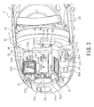
- the cleaner main body 11 is provided with a main body case 20, a dust collecting unit 50 (See Fig. 2 ) attached to the inside of the main body case 20, and the electric blower 24.
- a dust collecting unit chamber 22 having an upper opening 22A is formed, and a lid case 500 (See Fig. 1 ) is mounted on an upper portion of the main body case 20 capable of being opened or closed.
- a lid case 500 See Fig. 1
- the main body case 20 is configured so as not to be sealed by the lid case 500.
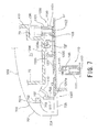
- a pop-up mechanism 1000 (See Fig. 7 ) for popping up a dust collecting container 410 ( Fig. 11 ) as a dust collecting section, which will be described later, is provided.
- a rotating body 900 (See Fig. 2 ) is rotatably attached to the cylindrical axle 17, the other end 18A of the torsion coil spring 18 is locked by a projection 902 (See Fig. 14 ) of an arm portion 901 of the rotating body 900, while the arm portion 901 is locked in the leg portion 501 of the lid case 500 so that the lid case 500 is urged clockwise.
- the lid case 500 is opened as shown by a chain line in Fig. 16 .
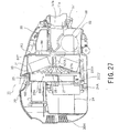
- connection air-passage portion 25 (connection air-passage) 25 (See Fig. 27 ) having a front surface opening 25B (See Fig. 14 ) is formed, and the connection air-passage portion 25 communicates with a suction opening 24A of the electric blower 24.
- a rotatable lattice member 600 is provided as shown in Fig. 14 , and this lattice member 600 is rotated by a motor M1 (See Fig. 37 ).
- the dust separation unit 400 is provided with a dust separation section 52 and a filter section 80 integrated with the dust separation section 52.
- connection opening 75 is formed in a left side wall section 74A of the dust collecting case portion 74, and a net filter NF3 is mounted over this connection opening 75.
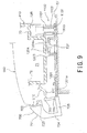
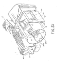
- the first opening/closing valve K1 closes the connection opening 54Aa of the guide air-passage body 57 as shown in Fig. 23 .
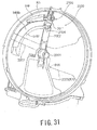
- the sixth opening/closing valve K6 is opened, and the third opening/closing valve K3 closes the connection opening 84A of the container case 81 as shown in Fig. 31 .
- the first opening/closing valve K1 is moved to the position indicated by the chain line shown in Fig. 23 , the connection opening 54Aa is opened, the sixth opening/closing valve K6 is closed as shown in Fig. 30 , and the third opening/closing valve K3 is moved to the position indicated by a chain line in Fig. 31 so as to open the connection opening 84A of the container case 81.
- the dust collecting unit 50 is mounted to the dust collecting unit chamber 22 of the cleaner main body 11, and as shown in Fig. 1 , the dust collecting hose 12 is connected to the connection port 11A of the cleaner main body 11, and on the other hand, the suction port body 15 is connected to the hand operation pipe 13 through the extension pipe 14.
- the electric blower 24 is driven.
- the air is then sucked from the suction opening 24A of the electric blower 24
- a negative pressure is caused into the container case 81 of the dust collecting unit 50 through a connection air-passage portion, not shown, and it is further caused into the dust collecting case portion 74 and the separation chamber portion 54 of the dust separation section 52 through the suction air-passage portion 56.
- This negative pressure acts on the dust collecting hose 12, the extension pipe 14, and the suction port body 15 through the guide air-passage body 57, and the dust is sucked with air from the suction port body 15.
- the sucked dust and air are sucked into the suction connection port 57a of the dust collecting unit 50 through the extension pipe 14 and the dust collecting hose 12.
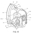
- the dust and air sucked into the suction connection port 57a are introduced into the separation chamber portion 54 of the dust separation section 52 through the guide air-passage body 57 and rotated in the separation chamber portion 54 counterclockwise in Fig. 10 . According to this air flow, the second opening/closing valve K2 is forced to be closed even if it is opened.
- the second opening/closing valve K2 is formed with the same curvature as that of the inner circumferential surface of the separation chamber portion 54 and provided so as to be flush with the inner circumferential surface, and hence, the valve is prevented to become a flow-passage resistance against air flowing through the separation chamber portion 54.
- the air sucked into the dust collecting chamber 73 is sucked into the suction air-passage portion 56 through the net filter NF3 and further, sucked into the container case 81 of the filter portion 80.
- the air sucked into the container case 81 passes through the pleated filter 104 of the pleated filter body 100, is sucked into the suction pipe 27 (See Fig. 21 ) in the connection air-passage portion 25 of the cleaner main body 11, and is then, sucked into the suction opening 24A of the electric air blower 24.
- the air sucked into the suction opening 24A of the electric blower 24 is discharged through the electric blower 24 from a discharge port 20H (See Fig. 21 ) of the cleaner main body 11 shown in Fig. 2 .
- the lock claw 707 of the clamp 700 is removed from the distal end portion 511 of the engagement member 510 in the lid case 500 and the lid case 500 is unlocked.
- the lid case 500 is opened by the torsion coil spring 18 (See Fig. 5 ) as shown by the chain line in Fig. 16 .
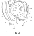
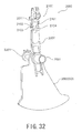
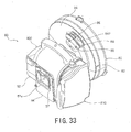
- the third opening/closing valve K3 closes the connection opening 84A of the container case 81, and the shaft portion 2011 of the arm 2002 presses the contact piece 87 of the sixth opening/closing valve K6 and opens the sixth opening/closing valve K6. That is, the outside-air introduction port 84F of the container case 81 is opened as shown in Fig. 33 .
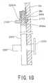
- the projection 2104 of the arm 2002 rides over the mountain portion 2104 of the pleated filter 104 in accordance with the rotation of the pleated filter 104, and at every time of riding over the mountain portion, the projection 2104 of the arm 2002 hits the mountain portion of the pleated filter 104 and shakes off the fine dust adhering to the pleated filter 104.
- the fine dust shaken off from the pleated filter 104 is returned by the outside air introduced through the outside-air introduction port 84F to the separation chamber 54 of the dust separation section 52 through the return air passage 2511. That is, the fine dust removed from the pleated filter 104 is discharged from the inside of the container case 81 into the separation chamber 54.
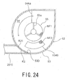
- the second opening/ closing valve K2 is opened by the outside air flowing through the return air passage 2511 as shown in Fig. 25 , the fine dust shaken off from the pleated filter 104 can be surely returned to the separation chamber 54 of the dust separation section 52.
- the outside air and the fine dust introduced into the separation chamber 54 are rotated counterclockwise in Fig. 10 , and by this rotation, the fine dust and the air are separated by the inertia force, and the separated fine dust are collected by the inertia force from the introduction opening 53A of the separation chamber 54 through the communication case portion 72 of the dust collecting container 410 to the dust collecting chamber 73.
- the air separated from the fine dust passes through the net filter NF1 (See Fig. 12 ) of the dust separating unit 55 and the net filter NF2 (See Fig. 25 ) of the opening 154B and is further sucked into the suction air-passage portion 56.
- the outside air sucked into the suction air-passage portion 56 is sucked into the suction pipe 27 through the bypass air-passage 2500, and then, sucked into the suction opening 24A of the electric blower 24 and discharged from the discharge port 20H of the cleaner main body 11.
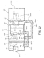
- the driving of the electric blower 24 is stopped, the lattice member 60 is backwardly rotated only for a predetermined angle, and as shown in Fig. 21 , the first opening/closing valve K1, the third opening/closing valve K3, and the fourth opening/closing valve 28 are opened, while the second opening/closing valve K2, the fifth opening/closing valve 2502, and the sixth opening/closing valve K6 are closed.
- an embodiment of air cleaning may include, other than that mentioned hereinabove, such structure that air is not directly blown against the pleated filter 104, and the fine dust floating in a space on the front side of the pleated filter 104 in the container case 81 and the fine dust collected on the bottom portion of the container case 81 are discharged by air flowing into the outside-air introduction port 84F to the outside of the container case 81 from the bottom-portion opening 82A.
- this embodiment is configured such that when the dust remover 2104 is brought into contact with the mountain portion of the pleated filter 104, the rotation operation of the pleated filter body 100 is transmitted to the arm 2002 on which the dust remover 2104 is provided.
- the present invention is not, however, limited to this embodiment, and for example, it may possible that the rotation of the pleated filter body 100 is transmitted to the arm 2002 by bringing the dust remover 2104 into contact with the holding frame of the pleated filter body 100.
Landscapes
- Engineering & Computer Science (AREA)
- Mechanical Engineering (AREA)
- Filters For Electric Vacuum Cleaners (AREA)
Applications Claiming Priority (2)
| Application Number | Priority Date | Filing Date | Title |
|---|---|---|---|
| JP2006229886A JP3990428B1 (ja) | 2006-08-25 | 2006-08-25 | 電気掃除機 |
| PCT/JP2007/057209 WO2008023474A1 (fr) | 2006-08-25 | 2007-03-30 | Aspirateur |
Publications (3)
| Publication Number | Publication Date |
|---|---|
| EP2064980A1 true EP2064980A1 (fr) | 2009-06-03 |
| EP2064980A4 EP2064980A4 (fr) | 2011-06-15 |
| EP2064980B1 EP2064980B1 (fr) | 2013-03-06 |
Family
ID=38640075
Family Applications (1)
| Application Number | Title | Priority Date | Filing Date |
|---|---|---|---|
| EP07740645A Ceased EP2064980B1 (fr) | 2006-08-25 | 2007-03-30 | Aspirateur |
Country Status (6)
| Country | Link |
|---|---|
| EP (1) | EP2064980B1 (fr) |
| JP (1) | JP3990428B1 (fr) |
| KR (1) | KR101012197B1 (fr) |
| CN (1) | CN101505646B (fr) |
| RU (1) | RU2386383C1 (fr) |
| WO (1) | WO2008023474A1 (fr) |
Families Citing this family (12)
| Publication number | Priority date | Publication date | Assignee | Title |
|---|---|---|---|---|
| JP5258438B2 (ja) * | 2008-07-31 | 2013-08-07 | 株式会社東芝 | 電気掃除機 |
| KR101250218B1 (ko) | 2012-05-15 | 2013-04-03 | 이춘우 | 전기 진공청소기 |
| KR101304213B1 (ko) | 2012-07-12 | 2013-09-10 | 이춘우 | 전기 진공청소기 |
| KR101245673B1 (ko) | 2012-07-12 | 2013-03-20 | 이춘우 | 진공청소기 |
| KR101372513B1 (ko) | 2013-01-17 | 2014-03-25 | 주식회사 칼라카나 | 진공 청소기 |
| US10278557B2 (en) | 2014-04-04 | 2019-05-07 | Techtronic Industries Co. Ltd. | Vacuum cleaner |
| KR101583029B1 (ko) * | 2014-09-18 | 2016-01-06 | 주식회사 중정 | 진공청소기 |
| WO2019026308A1 (fr) * | 2017-07-31 | 2019-02-07 | シャープ株式会社 | Aspirateur |
| KR20220010298A (ko) * | 2020-07-17 | 2022-01-25 | 삼성전자주식회사 | 청소기 |
| CN114680727B (zh) * | 2020-12-25 | 2023-09-19 | 莱克电气股份有限公司 | 一种吸尘器清洁装置及具有该清洁装置的吸尘器 |
| KR20220135545A (ko) * | 2021-03-30 | 2022-10-07 | 삼성전자주식회사 | 청소기 |
| GB2620166B (en) * | 2022-06-29 | 2024-12-04 | Dyson Technology Ltd | Dirt separator |
Family Cites Families (19)
| Publication number | Priority date | Publication date | Assignee | Title |
|---|---|---|---|---|
| US2364877A (en) * | 1944-12-12 | Suction cleaner | ||
| US2405129A (en) * | 1941-02-10 | 1946-08-06 | Hoover Co | Vacuum cleaning system |
| US2406915A (en) * | 1943-04-26 | 1946-09-03 | Hoover Co | Suction cleaner |
| JPS4851172U (fr) * | 1971-10-12 | 1973-07-04 | ||
| FI71660C (fi) * | 1983-12-16 | 1990-11-11 | Martti Ilmari Ollila | Sugare. |
| JP3268515B2 (ja) * | 1995-04-25 | 2002-03-25 | 三菱電機株式会社 | 電気掃除機 |
| CN1286423C (zh) * | 2001-12-18 | 2006-11-29 | 乐金电子(天津)电器有限公司 | 真空吸尘器用的旋转分离装置 |
| JP3699679B2 (ja) | 2001-12-28 | 2005-09-28 | 松下電器産業株式会社 | 電気掃除機 |
| KR100437106B1 (ko) * | 2002-05-31 | 2004-06-23 | 삼성광주전자 주식회사 | 진공청소기용 사이클론 집진장치 |
| CN1241518C (zh) * | 2002-05-31 | 2006-02-15 | 乐金电子(天津)电器有限公司 | 具备自动除尘装置的真空吸尘器 |
| JP4114406B2 (ja) * | 2002-06-05 | 2008-07-09 | 松下電器産業株式会社 | 電気掃除機 |
| JP2004358031A (ja) * | 2003-06-06 | 2004-12-24 | Matsushita Electric Ind Co Ltd | 電気掃除機 |
| JP3949615B2 (ja) * | 2003-06-09 | 2007-07-25 | 東芝テック株式会社 | 電気掃除機 |
| JP2005198935A (ja) | 2004-01-19 | 2005-07-28 | Matsushita Electric Ind Co Ltd | 電気掃除機 |
| JP2005237860A (ja) | 2004-02-27 | 2005-09-08 | Sanyo Electric Co Ltd | 電気掃除機 |
| JP3989461B2 (ja) * | 2004-05-06 | 2007-10-10 | 三洋電機株式会社 | 電気掃除機 |
| JP4444043B2 (ja) * | 2004-08-30 | 2010-03-31 | パナソニック株式会社 | 電気掃除機 |
| JP2006129976A (ja) | 2004-11-04 | 2006-05-25 | Sharp Corp | 電気掃除機 |
| JP4758111B2 (ja) | 2005-02-21 | 2011-08-24 | マスプロ電工株式会社 | テレビ受信用増幅装置,及び,テレビ受信システム |
-
2006
- 2006-08-25 JP JP2006229886A patent/JP3990428B1/ja not_active Expired - Fee Related
-
2007
- 2007-03-30 EP EP07740645A patent/EP2064980B1/fr not_active Ceased
- 2007-03-30 CN CN2007800315758A patent/CN101505646B/zh not_active Expired - Fee Related
- 2007-03-30 WO PCT/JP2007/057209 patent/WO2008023474A1/fr not_active Ceased
- 2007-03-30 KR KR1020097003717A patent/KR101012197B1/ko not_active Expired - Fee Related
- 2007-03-30 RU RU2009110762/12A patent/RU2386383C1/ru not_active IP Right Cessation
Also Published As
| Publication number | Publication date |
|---|---|
| EP2064980A4 (fr) | 2011-06-15 |
| JP3990428B1 (ja) | 2007-10-10 |
| KR101012197B1 (ko) | 2011-02-08 |
| WO2008023474A1 (fr) | 2008-02-28 |
| EP2064980B1 (fr) | 2013-03-06 |
| CN101505646A (zh) | 2009-08-12 |
| KR20090033492A (ko) | 2009-04-03 |
| JP2008048994A (ja) | 2008-03-06 |
| RU2386383C1 (ru) | 2010-04-20 |
| CN101505646B (zh) | 2012-01-04 |
Similar Documents
| Publication | Publication Date | Title |
|---|---|---|
| EP2064980B1 (fr) | Aspirateur | |
| KR101074541B1 (ko) | 진공 청소기 | |
| US20050241284A1 (en) | Dust collecting unit for use in cleaner | |
| EP1743562B1 (fr) | Aspirateur électrique | |
| JP4212608B2 (ja) | 電気掃除機 | |
| CN100544659C (zh) | 具有利用惯性力分离灰尘的分离器的真空吸尘器 | |
| JP4550922B2 (ja) | 電気掃除機及び電気掃除機のフィルター清掃方法 | |
| JP4267653B2 (ja) | 電気掃除機 | |
| JP4309905B2 (ja) | 電気掃除機 | |
| JP4342540B2 (ja) | 電気掃除機 | |
| JP4286851B2 (ja) | 電気掃除機 | |
| CN100462039C (zh) | 吸尘器 | |
| JP2008289661A (ja) | 電気掃除機 | |
| JP4256368B2 (ja) | 電気掃除機 | |
| JP4444256B2 (ja) | 電気掃除機 | |
| JP4286879B2 (ja) | 電気掃除機 | |
| JP4283290B2 (ja) | 電気掃除機 | |
| JP4550028B2 (ja) | 電気掃除機 | |
| JP2008067954A (ja) | 電気掃除機 | |
| JP2008200121A (ja) | 電気掃除機 | |
| JP2008289598A (ja) | 電気掃除機 |
Legal Events
| Date | Code | Title | Description |
|---|---|---|---|
| PUAI | Public reference made under article 153(3) epc to a published international application that has entered the european phase |
Free format text: ORIGINAL CODE: 0009012 |
|
| 17P | Request for examination filed |
Effective date: 20090318 |
|
| AK | Designated contracting states |
Kind code of ref document: A1 Designated state(s): AT BE BG CH CY CZ DE DK EE ES FI FR GB GR HU IE IS IT LI LT LU LV MC MT NL PL PT RO SE SI SK TR |
|
| AX | Request for extension of the european patent |
Extension state: AL BA HR MK RS |
|
| DAX | Request for extension of the european patent (deleted) | ||
| RBV | Designated contracting states (corrected) |
Designated state(s): DE GB |
|
| A4 | Supplementary search report drawn up and despatched |
Effective date: 20110512 |
|
| RIC1 | Information provided on ipc code assigned before grant |
Ipc: A47L 9/16 20060101ALI20110506BHEP Ipc: A47L 9/12 20060101ALI20110506BHEP Ipc: A47L 9/20 20060101ALI20110506BHEP Ipc: A47L 9/10 20060101AFI20080407BHEP |
|
| GRAP | Despatch of communication of intention to grant a patent |
Free format text: ORIGINAL CODE: EPIDOSNIGR1 |
|
| RIC1 | Information provided on ipc code assigned before grant |
Ipc: A47L 9/12 20060101ALI20120614BHEP Ipc: A47L 9/20 20060101ALI20120614BHEP Ipc: A47L 9/16 20060101ALI20120614BHEP Ipc: A47L 9/10 20060101AFI20120614BHEP |
|
| GRAS | Grant fee paid |
Free format text: ORIGINAL CODE: EPIDOSNIGR3 |
|
| GRAA | (expected) grant |
Free format text: ORIGINAL CODE: 0009210 |
|
| AK | Designated contracting states |
Kind code of ref document: B1 Designated state(s): DE GB |
|
| REG | Reference to a national code |
Ref country code: GB Ref legal event code: FG4D |
|
| REG | Reference to a national code |
Ref country code: DE Ref legal event code: R096 Ref document number: 602007028882 Country of ref document: DE Effective date: 20130502 |
|
| PLBE | No opposition filed within time limit |
Free format text: ORIGINAL CODE: 0009261 |
|
| STAA | Information on the status of an ep patent application or granted ep patent |
Free format text: STATUS: NO OPPOSITION FILED WITHIN TIME LIMIT |
|
| 26N | No opposition filed |
Effective date: 20131209 |
|
| REG | Reference to a national code |
Ref country code: DE Ref legal event code: R097 Ref document number: 602007028882 Country of ref document: DE Effective date: 20131209 |
|
| REG | Reference to a national code |
Ref country code: DE Ref legal event code: R082 Ref document number: 602007028882 Country of ref document: DE Representative=s name: HASELTINE LAKE KEMPNER LLP, DE Ref country code: DE Ref legal event code: R082 Ref document number: 602007028882 Country of ref document: DE Representative=s name: HASELTINE LAKE LLP, DE Ref country code: DE Ref legal event code: R081 Ref document number: 602007028882 Country of ref document: DE Owner name: TOSHIBA LIFESTYLE PRODUCTS & SERVICES CORPORAT, JP Free format text: FORMER OWNERS: KABUSHIKI KAISHA TOSHIBA, TOKIO/TOKYO, JP; TOSHIBA CONSUMER ELECTRONICS HOLDINGS CORP., TOKYO, JP; TOSHIBA HOME APPLIANCES CORP., TOKYO, JP |
|
| REG | Reference to a national code |
Ref country code: GB Ref legal event code: 732E Free format text: REGISTERED BETWEEN 20170105 AND 20170111 |
|
| REG | Reference to a national code |
Ref country code: GB Ref legal event code: 732E Free format text: REGISTERED BETWEEN 20170518 AND 20170524 |
|
| PGFP | Annual fee paid to national office [announced via postgrant information from national office to epo] |
Ref country code: DE Payment date: 20190319 Year of fee payment: 13 Ref country code: GB Payment date: 20190327 Year of fee payment: 13 |
|
| REG | Reference to a national code |
Ref country code: DE Ref legal event code: R119 Ref document number: 602007028882 Country of ref document: DE |
|
| PG25 | Lapsed in a contracting state [announced via postgrant information from national office to epo] |
Ref country code: DE Free format text: LAPSE BECAUSE OF NON-PAYMENT OF DUE FEES Effective date: 20201001 |
|
| GBPC | Gb: european patent ceased through non-payment of renewal fee |
Effective date: 20200330 |
|
| PG25 | Lapsed in a contracting state [announced via postgrant information from national office to epo] |
Ref country code: GB Free format text: LAPSE BECAUSE OF NON-PAYMENT OF DUE FEES Effective date: 20200330 |