EP2065018B1 - Verfahren zur Befestigung einer mit Klammern fixierbaren Lauffuß-Prothese - Google Patents
Verfahren zur Befestigung einer mit Klammern fixierbaren Lauffuß-Prothese Download PDFInfo
- Publication number
- EP2065018B1 EP2065018B1 EP08019475A EP08019475A EP2065018B1 EP 2065018 B1 EP2065018 B1 EP 2065018B1 EP 08019475 A EP08019475 A EP 08019475A EP 08019475 A EP08019475 A EP 08019475A EP 2065018 B1 EP2065018 B1 EP 2065018B1
- Authority
- EP
- European Patent Office
- Prior art keywords
- foot
- main axis
- bracket
- point
- socket
- Prior art date
- Legal status (The legal status is an assumption and is not a legal conclusion. Google has not performed a legal analysis and makes no representation as to the accuracy of the status listed.)
- Not-in-force
Links
- 238000000034 method Methods 0.000 title claims description 12
- 210000003141 lower extremity Anatomy 0.000 title claims description 4
- 210000003127 knee Anatomy 0.000 claims abstract description 30
- 230000003068 static effect Effects 0.000 claims abstract description 8
- 239000002131 composite material Substances 0.000 claims abstract description 5
- 210000002683 foot Anatomy 0.000 claims description 132
- 238000002266 amputation Methods 0.000 claims description 18
- OKTJSMMVPCPJKN-UHFFFAOYSA-N Carbon Chemical compound [C] OKTJSMMVPCPJKN-UHFFFAOYSA-N 0.000 claims description 4
- 229920000271 Kevlar® Polymers 0.000 claims description 4
- 229910052799 carbon Inorganic materials 0.000 claims description 4
- 239000004744 fabric Substances 0.000 claims description 4
- 239000000835 fiber Substances 0.000 claims description 4
- 239000004761 kevlar Substances 0.000 claims description 4
- 210000003789 metatarsus Anatomy 0.000 claims description 4
- 230000002746 orthostatic effect Effects 0.000 claims description 4
- 239000003292 glue Substances 0.000 claims description 3
- 238000003475 lamination Methods 0.000 claims 1
- 230000037396 body weight Effects 0.000 abstract 1
- 210000000689 upper leg Anatomy 0.000 description 3
- 230000000694 effects Effects 0.000 description 2
- 210000003414 extremity Anatomy 0.000 description 2
- 241001455214 Acinonyx jubatus Species 0.000 description 1
- 241000761557 Lamina Species 0.000 description 1
- 230000002745 absorbent Effects 0.000 description 1
- 239000002250 absorbent Substances 0.000 description 1
- 210000001361 achilles tendon Anatomy 0.000 description 1
- 210000000544 articulatio talocruralis Anatomy 0.000 description 1
- 238000006243 chemical reaction Methods 0.000 description 1
- 210000004394 hip joint Anatomy 0.000 description 1
- 210000003205 muscle Anatomy 0.000 description 1
- 230000003387 muscular Effects 0.000 description 1
- 230000001141 propulsive effect Effects 0.000 description 1
- 230000009192 sprinting Effects 0.000 description 1
Images


Classifications
-
- A—HUMAN NECESSITIES
- A61—MEDICAL OR VETERINARY SCIENCE; HYGIENE
- A61F—FILTERS IMPLANTABLE INTO BLOOD VESSELS; PROSTHESES; DEVICES PROVIDING PATENCY TO, OR PREVENTING COLLAPSING OF, TUBULAR STRUCTURES OF THE BODY, e.g. STENTS; ORTHOPAEDIC, NURSING OR CONTRACEPTIVE DEVICES; FOMENTATION; TREATMENT OR PROTECTION OF EYES OR EARS; BANDAGES, DRESSINGS OR ABSORBENT PADS; FIRST-AID KITS
- A61F2/00—Filters implantable into blood vessels; Prostheses, i.e. artificial substitutes or replacements for parts of the body; Appliances for connecting them with the body; Devices providing patency to, or preventing collapsing of, tubular structures of the body, e.g. stents
- A61F2/50—Prostheses not implantable in the body
- A61F2/60—Artificial legs or feet or parts thereof
- A61F2/66—Feet; Ankle joints
-
- A—HUMAN NECESSITIES
- A61—MEDICAL OR VETERINARY SCIENCE; HYGIENE
- A61F—FILTERS IMPLANTABLE INTO BLOOD VESSELS; PROSTHESES; DEVICES PROVIDING PATENCY TO, OR PREVENTING COLLAPSING OF, TUBULAR STRUCTURES OF THE BODY, e.g. STENTS; ORTHOPAEDIC, NURSING OR CONTRACEPTIVE DEVICES; FOMENTATION; TREATMENT OR PROTECTION OF EYES OR EARS; BANDAGES, DRESSINGS OR ABSORBENT PADS; FIRST-AID KITS
- A61F2/00—Filters implantable into blood vessels; Prostheses, i.e. artificial substitutes or replacements for parts of the body; Appliances for connecting them with the body; Devices providing patency to, or preventing collapsing of, tubular structures of the body, e.g. stents
- A61F2/50—Prostheses not implantable in the body
- A61F2/76—Means for assembling, fitting or testing prostheses, e.g. for measuring or balancing, e.g. alignment means
-
- A—HUMAN NECESSITIES
- A61—MEDICAL OR VETERINARY SCIENCE; HYGIENE
- A61F—FILTERS IMPLANTABLE INTO BLOOD VESSELS; PROSTHESES; DEVICES PROVIDING PATENCY TO, OR PREVENTING COLLAPSING OF, TUBULAR STRUCTURES OF THE BODY, e.g. STENTS; ORTHOPAEDIC, NURSING OR CONTRACEPTIVE DEVICES; FOMENTATION; TREATMENT OR PROTECTION OF EYES OR EARS; BANDAGES, DRESSINGS OR ABSORBENT PADS; FIRST-AID KITS
- A61F2/00—Filters implantable into blood vessels; Prostheses, i.e. artificial substitutes or replacements for parts of the body; Appliances for connecting them with the body; Devices providing patency to, or preventing collapsing of, tubular structures of the body, e.g. stents
- A61F2/50—Prostheses not implantable in the body
- A61F2/5044—Designing or manufacturing processes
- A61F2/5046—Designing or manufacturing processes for designing or making customized prostheses, e.g. using templates, finite-element analysis or CAD-CAM techniques
-
- A—HUMAN NECESSITIES
- A61—MEDICAL OR VETERINARY SCIENCE; HYGIENE
- A61F—FILTERS IMPLANTABLE INTO BLOOD VESSELS; PROSTHESES; DEVICES PROVIDING PATENCY TO, OR PREVENTING COLLAPSING OF, TUBULAR STRUCTURES OF THE BODY, e.g. STENTS; ORTHOPAEDIC, NURSING OR CONTRACEPTIVE DEVICES; FOMENTATION; TREATMENT OR PROTECTION OF EYES OR EARS; BANDAGES, DRESSINGS OR ABSORBENT PADS; FIRST-AID KITS
- A61F2/00—Filters implantable into blood vessels; Prostheses, i.e. artificial substitutes or replacements for parts of the body; Appliances for connecting them with the body; Devices providing patency to, or preventing collapsing of, tubular structures of the body, e.g. stents
- A61F2/02—Prostheses implantable into the body
- A61F2/30—Joints
- A61F2002/30001—Additional features of subject-matter classified in A61F2/28, A61F2/30 and subgroups thereof
- A61F2002/30316—The prosthesis having different structural features at different locations within the same prosthesis; Connections between prosthetic parts; Special structural features of bone or joint prostheses not otherwise provided for
- A61F2002/30329—Connections or couplings between prosthetic parts, e.g. between modular parts; Connecting elements
- A61F2002/30433—Connections or couplings between prosthetic parts, e.g. between modular parts; Connecting elements using additional screws, bolts, dowels, rivets or washers e.g. connecting screws
-
- A—HUMAN NECESSITIES
- A61—MEDICAL OR VETERINARY SCIENCE; HYGIENE
- A61F—FILTERS IMPLANTABLE INTO BLOOD VESSELS; PROSTHESES; DEVICES PROVIDING PATENCY TO, OR PREVENTING COLLAPSING OF, TUBULAR STRUCTURES OF THE BODY, e.g. STENTS; ORTHOPAEDIC, NURSING OR CONTRACEPTIVE DEVICES; FOMENTATION; TREATMENT OR PROTECTION OF EYES OR EARS; BANDAGES, DRESSINGS OR ABSORBENT PADS; FIRST-AID KITS
- A61F2/00—Filters implantable into blood vessels; Prostheses, i.e. artificial substitutes or replacements for parts of the body; Appliances for connecting them with the body; Devices providing patency to, or preventing collapsing of, tubular structures of the body, e.g. stents
- A61F2/50—Prostheses not implantable in the body
- A61F2002/5016—Prostheses not implantable in the body adjustable
- A61F2002/5018—Prostheses not implantable in the body adjustable for adjusting angular orientation
-
- A—HUMAN NECESSITIES
- A61—MEDICAL OR VETERINARY SCIENCE; HYGIENE
- A61F—FILTERS IMPLANTABLE INTO BLOOD VESSELS; PROSTHESES; DEVICES PROVIDING PATENCY TO, OR PREVENTING COLLAPSING OF, TUBULAR STRUCTURES OF THE BODY, e.g. STENTS; ORTHOPAEDIC, NURSING OR CONTRACEPTIVE DEVICES; FOMENTATION; TREATMENT OR PROTECTION OF EYES OR EARS; BANDAGES, DRESSINGS OR ABSORBENT PADS; FIRST-AID KITS
- A61F2/00—Filters implantable into blood vessels; Prostheses, i.e. artificial substitutes or replacements for parts of the body; Appliances for connecting them with the body; Devices providing patency to, or preventing collapsing of, tubular structures of the body, e.g. stents
- A61F2/50—Prostheses not implantable in the body
- A61F2/60—Artificial legs or feet or parts thereof
- A61F2/66—Feet; Ankle joints
- A61F2002/6614—Feet
- A61F2002/6657—Feet having a plate-like or strip-like spring element, e.g. an energy-storing cantilever spring keel
- A61F2002/6678—L-shaped
-
- A—HUMAN NECESSITIES
- A61—MEDICAL OR VETERINARY SCIENCE; HYGIENE
- A61F—FILTERS IMPLANTABLE INTO BLOOD VESSELS; PROSTHESES; DEVICES PROVIDING PATENCY TO, OR PREVENTING COLLAPSING OF, TUBULAR STRUCTURES OF THE BODY, e.g. STENTS; ORTHOPAEDIC, NURSING OR CONTRACEPTIVE DEVICES; FOMENTATION; TREATMENT OR PROTECTION OF EYES OR EARS; BANDAGES, DRESSINGS OR ABSORBENT PADS; FIRST-AID KITS
- A61F2220/00—Fixations or connections for prostheses classified in groups A61F2/00 - A61F2/26 or A61F2/82 or A61F9/00 or A61F11/00 or subgroups thereof
- A61F2220/0025—Connections or couplings between prosthetic parts, e.g. between modular parts; Connecting elements
- A61F2220/0041—Connections or couplings between prosthetic parts, e.g. between modular parts; Connecting elements using additional screws, bolts, dowels or rivets, e.g. connecting screws
Definitions
- the present invention relates to a foot for a lower limb prosthesis which enables a novice user to run while minimizing fatigue, and enables an expert athlete to improve performance in sports competitions.
- a prosthetic foot used for running is different from those used for walking, as its functionality is different; running feet are also made of composite material, but always consist of several laminas connected together in such a manner as to perform the functionality of the foot and of the ankle joint.
- a running foot consists of only one lamina, and hence lacks a lamina which morphologically defines the heel, such as in the human foot: in this respect, this latter lamina is useless for sprinting, i.e. fast running, achieved by bearing on the foot front, and is also useless in a middle-distance race in which the lamina flexes during loading, as in the case of a spring, in such a manner as to increase the contact surface and to form a type of virtual heel.
- the object of the present invention is to enable a new user to commence sporting activities while minimizing the energy consumed and hence fatigue, and to enable a sporting athlete to improve performance, by optimizing the mechanical behaviour of the foot.
- An example of a running foot is the flex-foot CHEETAH, manufactured by Ossur.
- the object of the present invention is therefore to provide a method for positioning a running foot which during use accurately simulates the functionality of the human foot.
- FIGS. 1 and 2 show a prosthetic foot (1), defined by a J-shaped lamina of composite material which during use, particularly after the loading stage, provides an elastic response which enables the user to advance during running.
- This foot (1) can be fixed by a TT bracket (2) directly to a socket (3) in the case of transtibial amputations, as shown in Figure 1
- the foot (1) can be fixed to a TF bracket (2a) connectable to a mechanical knee (G) in the case of transfemoral amputations, as shown in Figure 2 .
- the mechanical knee (G) is connected to a socket (3a) for subjects with transfemoral amputations.
- the TT bracket (2), the socket (3) and the foot (1) form a transtibial prosthesis
- the foot (12), the TF bracket (2a), the mechanical knee (G) and the socket (3a) form a transfemoral prosthesis.
- this socket (3, 3a) has a main axis (5) passing through a point (4) identifying the femoral epicondyle, real or virtual according to the type of user amputation, and coinciding with the centre of instantaneous rotation of the user's knee during mid-stance.
- the foot (1) is fixed to a TF bracket (2a) which is connected to the socket (3a) via a mechanical knee (G) of known type.
- G mechanical knee
- the femoral epicondyle to which reference is made is virtual and corresponds to the centre of rotation of the mechanical knee during mid-stance, i.e. when the user's femur is perpendicular to the ground.
- a segment (9) joining a first point (7) of tangency between the foot (1) and the ground line (6) perpendicular to the main axis (5) and a second point (8) of tangency between the foot (1) and a straight line (10) parallel to the main axis is inclined by an angle ⁇ , between 30° and 50°, to the ground line (6) perpendicular to the main axis, said point (8) of tangency lying along a line (11) inclined by an angle ⁇ , between 20° and 40°, to said main axis (5), and intersecting said main axis at the point (4).
- the angle ⁇ is 40° and the angle ⁇ , is 25°.
- the first point (7) of tangency represents the 5 th metatarsus of a human foot
- the second point (8) of tangency defining the vertex of the curve and the virtual heel of the foot (1) according to the invention.
- the main axis (5) coincides with the loading straight line, the loading straight line meaning that line along which the athlete discharges weight when in the orthostatic position after connecting the prosthesis.
- the distance D1 of the first point (7) of tangency from said main axis (5), representative of the distance between the 5 th metatarsus and the loading straight line is less than the distance D2 of the second point (8) of tangency from said main axis (5), representative of the distance between the virtual heel and the loading straight line.
- the distance D1 is equal to one half of said distance D2.
- the prosthetic foot has a length Lp, this length being the distance between the point (8) representative of the virtual heel and the front terminal end or tip (17) of the foot along an axis parallel to the ground line (6), and is equal to 2xD2 ⁇ 20 mm for all classes.
- the foot (1) as shown in Figure 4 , comprises a rectilinear first portion (12) for fixing the TT or TF bracket (2 or 2a), and inclined to the main axis (5) by an angle ⁇ between 10° and 20°, preferably 15°.
- the foot (1) also comprises:
- users of height between 170 and 180 cm and shoe size between 38 and 41 pertain to class III, for whom the foot used will correspond to the numerical values of feet used by users of class IV divided by a factor of 1.1 as indicated in Figure 12a .
- class IV For users pertaining to class II, of height between 160 and 170 cm and shoe size between 34 and 37, the numerical values of class IV are divided by a factor of 1.22 as indicated in Figure 13 .
- class IV For users pertaining to class I, of height between 150 and 160 cm and shoe size between 30 and 33, the numerical values of class IV are divided by a factor of 1.366 as indicated in Figure 14 .
- the radius R1 which generally defines the initial curvature of the foot (1), representative of the human limb of the first portion of the Achilles heel, is equal to 100 ⁇ 2 mm, while C1 is distant from the main axis (5) by 150 ⁇ 50 mm and distant from the ground line (6) by 352 ⁇ 100 mm less the thickness of the foot at its point of contact with the ground.
- the radius R2 which defines the virtual heel, is equal to 150 ⁇ 50 mm with its centre of curvature falling on the main axis (5) and a distance from the ground line (6) equal to the distance of the heel vertex (8) from the same ground line (6) less the thickness of the foot at its point of contact with the ground, i.e. 100 ⁇ 65 mm.
- the centre C2 of the foot (1) is the centre of the virtual ankle during foot alignment.
- the radius R3, which defines the lower portion of the virtual heel, is of 130 ⁇ 40 mm with its centre of curvature C3 positioned at about 22 ⁇ 7 mm from the loading straight line (5) and 129 ⁇ 22 mm from the vertex (8) of the virtual heel, in contrast to known feet in which this centre of curvature is to the front of the loading straight line.
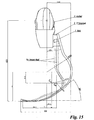
- the portion 15 joining the virtual heel to the virtual foot front is rectilinear, whereas known feet present curved portions, as shown in Figure 15 .
- the virtual foot front (14) is defined by:
- the width of the class IV foot front H or cross-section of the foot (1), examined in detail, according to the invention is 90 ⁇ 5 mm, i.e. much wider than known feet, such as to ensure equilibrium between the two limbs, i.e. the healthy and the prosthetic, during running.
- the cross-section H is 80 ⁇ 5 mm for class III, 70 ⁇ 5 mm for class II and 60 ⁇ 5 mm for class I.
- the points C1 , C2. C3, C4 and C5 and their positions are characteristic of all classes of the foot (1), and together with the radii R1 , R2, R3, R 4 , R5 less the scaling factor defining the numerical values of the individual class, they completely define the morphology of the foot (1) of all the different classes.
- the first rectilinear portion 12 is fixed to the rear of the socket (3) by a TT bracket (2) in the transtibial case, shown in Figures from 5 to 7, and is fixed to a TF bracket (2a) in the transfemoral case, shown in Figures from 8 to 10, itself fixed to the mechanical knee.
- the first portion of the foot (1) i.e. rectilinear (12) is fixed to the bracket by fixing elements, for example screws.
- the TT bracket (2) which is laminated together with the socket (3) to ensure suitable strength of the structure, comprises:
- the first rectilinear portion (12) of the foot (1) is connected to a TF bracket (2a) shown in Figures 8, 9 and 10 , and is connected to a mechanical knee (G), connected in its turn to the socket (3a).
- the TF bracket (2a) has an upper flat surface (2a.1) presenting for example four through holes (2a.2) for its fixing by fixing elements, for example screws, to the mechanical knee (G), and a rear flat upper surface (2a.3) inclined at 15° to an axis perpendicular to the upper flat surface (2a.1); the foot (1) is positioned on the 15°-inclined surface (2a.3) and fixed, for example by two screws inserted through two holes (2a.4), as shown in Figures from 8 to 11.
- an upper flat surface (2a.1) presenting for example four through holes (2a.2) for its fixing by fixing elements, for example screws, to the mechanical knee (G), and a rear flat upper surface (2a.3) inclined at 15° to an axis perpendicular to the upper flat surface (2a.1); the foot (1) is positioned on the 15°-inclined surface (2a.3) and fixed, for example by two screws inserted through two holes (2a.4), as shown in Figures from 8 to 11.
- the foot (1) is formed by superposing layers of unidirectional carbon/Kevlar fibre fabric and layers of mutually crossing carbon/Kevlar fibre fabric.
- Each of these layers has a longitudinal elastic traction modulus E of about 116,000 Mpa and 58,000 Mpa respectively, and an ultimate tensile strength of about 1300 Mpa and 650 Mpa respectively.
- the thickness of the foot (1) or rather of the composite material lamina increases starting from a minimum value at the tip (17) of the final rectilinear portion (14c) of the foot front (14) to a maximum value at the upper end (18) of the foot (1), as shown in Figure 4 .
- the foot (1) has eight different thicknesses as shown in Figure 12 : specifically for athletes pertaining to class IV, the lamina has a thickness of 4.5 ⁇ 0.65 mm in the initial region starting from the point (17), and extends along the foot development for 150 mm, the second region of length 20 mm has a thickness of 5.19 ⁇ 0.65 mm, the third region of length 70 mm has a thickness of 7.29 ⁇ 0.65 mm, the fourth region of length 20 mm has a thickness of 8.25 ⁇ 0.65 mm, the fifth region of length 70 mm has a thickness of 9.38 ⁇ 0.65 mm, the sixth region of length 33 mm has a thickness of 9.8 ⁇ 0.65 mm, the last two regions are measured from the upper end (18) of the foot (1), at 447 mm from the ground line (6), with the seventh region having a thickness of 12 mm ⁇ 0.65 mm and a length of 120 mm from an axis parallel to the main axis (5) and the eighth region having a thickness of
- the thickness in the individual regions is calculated by dividing by the scaling factor, which is 1.1 in the case of class III, 1.2 in the case of class II and 1.366 in the case of class I, as shown in Figures 12a , 13 , 14 with a tolerance of 0.65 mm.
- the foot thickness increases for all classes from one region to another, starting from the tip (17), where it has its minimum value, to the upper end (18), where it has its maximum value, by a factor for adjacent regions which is between 1.02 and 1.40; the ratio between the foot thickness at the tip (17) and at the upper end (18) is 2.7 ⁇ 0.2 for all classes.
- each foot class based on the weight of the user, these sub-classes varying in terms of different thickness: in this respect the strength and the elastic response of the foot (1) are in relation to the load applied to it, which is a function of the weight of the user.
- the foot (1) is positioned in proximity to the TT bracket (2) and to the socket (3) worn by the user in an orthostatic position, with provisional fixing and positioning.
- the TT bracket (2) is fixed onto the socket (3) with glue.
- the TT bracket (2) is positioned with its flat vertical surface (2.1) adhering to the socket (3) and fixed, as already stated, by glue such that the flat surface (2.2) of the TT bracket (2) on which the foot (1) is to be fixed will have an inclination of 15° to the main axis (5) passing through the point (4) identifying the real femoral epicondyle.
- the TT bracket (2) is then laminated with the socket such that they become a single structure.
- the foot (1), rigid with the TT bracket (2), once fixed by fixing elements, for example two screws, must be positioned together with the TT bracket (2) on the socket (3), such that the upper end (18) of the foot (1) is at a distance D3 from the ground line (6) of 440 ⁇ 10 mm, for example 447 mm and hence at about 100 ⁇ 40 mm from the point (4), and at a distance D4 from the main axis (5) and loading straight line of 65 ⁇ 5 mm.
- the fixing point for the foot (1) has been established such as to enable the functionality of the prosthetic foot (1) to approach that of the human foot, in which the Achilles tendon, for class IV users, lies at about 100 mm below the centre of the popliteal cavity formed by the union of the Gastrocnem and Soleum muscles, and is responsible for 90% of the foot elasticity.
- D3 becomes equal to 410 ⁇ 20 mm, for example 416 mm for class III, 360 ⁇ 30 mm, for example 365 mm for class II, and 320 ⁇ 10 mm, for example 322 mm for class I
- D4 becomes 59 ⁇ 5 mm for class III, 53 ⁇ 5 mm for class II, and 49 ⁇ 4 mm for class I.
- the foot (1) is fixed to the TF bracket (2a) which itself is fixed to the mechanical knee (G) by fixing elements, for example four screws.
- the foot (1) is fixed by the following steps:
- the alignment is done in the same manner, but the distance D3 of the upper end (18) of the foot (1) from the ground line (6) and the distance D4 of the upper end (18) from the main axis vary by the scaling factor: D3 becomes equal to 410 ⁇ 20 mm, for example 416 mm for class III, 360 ⁇ 30 mm, for example 365 mm for class II, and 320 ⁇ 10 mm, for example 322 mm for class I, and D4 becomes 59 ⁇ 5 mm for class III, 53 ⁇ 5 mm for class II, and 49 ⁇ 4 mm for class I.
- the foot (1) presents a segment (11) with a predetermined inclination between the point (4) and the vertex (8) of the virtual heel of 30° ⁇ 5° to the main axis (5), and a segment (9) with an inclination of 40° ⁇ 5° between the point of tangency (7) indicative of the 5 th metatarsus and the vertex (8) of the virtual heel, such as to best simulate the plantar flexure of the human foot which in the case of normal athletes is of 40°.
- the foot (1) results in smoother running biomechanics, enabling the expert athlete to achieve better performance in sporting competitions, and enabling the beginner to more easily initiate a sporting career as the foot (1) of the new invention minimizes the energy consumed in running and hence the user fatigue.
Landscapes
- Health & Medical Sciences (AREA)
- Transplantation (AREA)
- Heart & Thoracic Surgery (AREA)
- Oral & Maxillofacial Surgery (AREA)
- Engineering & Computer Science (AREA)
- Biomedical Technology (AREA)
- Cardiology (AREA)
- Vascular Medicine (AREA)
- Life Sciences & Earth Sciences (AREA)
- Animal Behavior & Ethology (AREA)
- General Health & Medical Sciences (AREA)
- Public Health (AREA)
- Veterinary Medicine (AREA)
- Orthopedic Medicine & Surgery (AREA)
- Prostheses (AREA)
Claims (7)
- Verfahren zur Positionierung eines prothetischen Lauffußes (1) für eine Beinprothese, der aus Verbundmaterial von J-Form gebildet ist und der im Falle eines Benutzers mit transtibialer Amputation über eine TT-Klammer (2) mit einem Verbindungsstück (3) verbunden ist oder im Falle eines Benutzers mit transfemoraler Amputation über eine TF-Klammer (2a) mit einem bekannten mechanischen Knie (G) verbunden ist, das selbst mit einem Verbindungsstück (3a) verbunden ist, wobei das Verbindungsstück (3 oder 3a) eine Hauptachse (5) aufweist, die durch einen Punkt (4) verläuft, der den femoralen Epicondylus im Fall eines Benutzers mit transtibialer Amputation tatsächlich und im Fall eines Benutzers mit transfemoraler Amputation gedacht sowie zusammenfallend mit dem Drehpunkt des mechanischen Knies (G) während einer Mittelstellung kennzeichnet,
wobei der Fuß eine derartige Morphologie aufweist, dass ein Segment (9), das einen Punkt (7), der für den gedachten 5. Metatarsus kennzeichnend ist und ein Berührungspunkt zwischen dem Fuß (1) und einer Bodenlinie (6) senkrecht zu der Hauptachse (5) ist, mit einem Punkt (8) verbindet, der für die gedachte Ferse kennzeichnend ist und ein Berührungspunkt zwischen dem Fuß (1) und einer geraden Linie (10) parallel zu der Hauptachse (5) ist, um einen Winkel α von zwischen 30° und 50° gegenüber der Bodenlinie (6) geneigt ist und dass der Punkt (8), der für die gedachte Ferse kennzeichnend ist, entlang einer Linie liegt, die um einen Winkel β von zwischen 20° und 40° gegenüber der Hauptachse (5) geneigt ist und die Hauptachse an dem Punkt (4) schneidet, dadurch gekennzeichnet, dass im transtibialen Fall das Verfahren die folgenden Schritte aufweist:- Positionieren des Fußes (1) nahe der TT-Klammer (2) und nahe des von dem Nutzer getragenen Verbindungsstücks (3) mit provisorischer Befestigung in der Weise, dass der Abstand D3 zwischen dem oberen freien Ende (18) des Fußes (1) und der Bodenlinie (6) entlang einer Achse (10) parallel zu der Hauptachse (5) 440 ± 10 mm oder 410 ± 20 mm oder 360 ± 30 mm oder 320 ± 10 mm beträgt und der Abstand D4 des oberen freien Endes (18) des Fußes (1) von der Hauptachse (5) entsprechend 65 ± 5 mm oder 59 ± 5 mm oder 53 ± 5 mm oder 49 ± 4 mm beträgt,- Markieren der Position der TT-Klammer (2) an dem Verbindungsstück (3) auf der Basis dieser anfänglichen Positionierung derart, um zu ermöglichen, dass der Fuß (1) korrekt positioniert wird, dann Befestigen der TT-Klammer (2) mit Klebstoff an dem Verbindungsstück (3),- nach einem Laminierungsschritt, der von einem Orthopädietechniker an dem Verbindungsstück (3) und der TT-Klammer (2) ausgeführt wird, so dass diese zu einer einzigen Struktur werden, Befestigen des Fußes an der TT-Klammer (2) durch Befestigungselemente, wie zum Beispiel Schrauben,
und dass im transfemoralen Fall das Verfahren die folgenden Schritte aufweist:- Befestigen des mechanischen Knies (G) an dem Verbindungsstück (3a), das von dem Benutzer in einer orthostatischen Position getragen wird,- Befestigen der TF-Klammer (2a) an dem mechanischen Knie (G) durch Befestigungselemente,- Befestigen des Fußes (1) an der TF-Klammer (2a) durch Befestigungselemente in der Weise, dass der Abstand D3 zwischen dem oberen freien Ende (18) des Fußes (1) und der Bodenlinie (6) entlang einer Achse (10) parallel zu der Hauptachse (5) 440 ± 10 mm oder 410 ± 20 mm oder 360 ± 30 mm oder 320 ± 10 mm beträgt und der Abstand D4 des oberen freien Endes (18) des Fußes (1) von der Hauptachse (5) entsprechend 65 ± 5 mm oder 59 ± 5 mm oder 53 ± 5 mm oder 49 ± 4 mm beträgt. - Verfahren zur Positionierung eines prothetischen Fußes (1) nach Anspruch 1, dadurch gekennzeichnet, dass es den folgenden Schritt einer statischen Ausrichtung aufweist:- Fixieren der TT- oder TF-Klammer (2 oder 2a) an dem Verbindungsstück in dem transtibialen Fall oder an dem Knie (G) in dem transfemoralen Fall in der Weise, dass der Fuß (1) eine Neigung von 15° gegenüber der Hauptachse (5) oder geraden Belastungslinie aufweist, wenn er an der jeweiligen TT- oder TF-Klammer (2 oder 2a) befestigt ist.
- Verfahren nach Anspruch 1, dadurch gekennzeichnet, dass der Abstand D1 des Berührungspunktes (7), der für den 5. Metatarsus kennzeichnend ist, von der Hauptachse (5) kleiner ist als der Abstand D2 des Berührungspunktes (8), der für den gedachten 5. Metatarsus kennzeichnend ist, von der Hauptachse (5) .
- Verfahren nach Anspruch 1, dadurch gekennzeichnet, dass der Abstand D1 gleich der Hälfte des Abstandes D2 ist.
- Verfahren nach Anspruch 1, dadurch gekennzeichnet, dass es einen geradlinigen Abschnitt (12) aufweist, der gegenüber der Hauptachse (5) um einen Winkel α von zwischen 10° und 20° geneigt ist.
- Verfahren nach Anspruch 1, dadurch gekennzeichnet, dass es durch Übereinanderlagern von Schichten eines Stoffs mit unidirektionalen Kohle-/Kevlar-Fasern und Schichten eines Stoffs mit sich gegenseitig kreuzenden Kohle-/Kevlar-Fasern gebildet wird.
- Verfahren nach Anspruch 1, gekennzeichnet durch eine Zunahme seiner Dicke von einem Bereich zu einem anderen, beginnend von einer Spitze (17), wo er seinen minimalen Wert aufweist, zu einem oberen Ende (18), wo er seinen maximalen Wert aufweist, um einen Faktor für benachbarte Bereiche, der zwischen 1,02 und 1,40 liegt, während das Verhältnis zwischen der
Fuß-Dicke an der Spitze (17) und an dem oberen Ende (18) 2,7 ± 0,2 beträgt.
Applications Claiming Priority (1)
| Application Number | Priority Date | Filing Date | Title |
|---|---|---|---|
| IT002148A ITMI20072148A1 (it) | 2007-11-09 | 2007-11-09 | Piede da correre per protesi di arto inferiore, fissabile a staffa |
Publications (3)
| Publication Number | Publication Date |
|---|---|
| EP2065018A2 EP2065018A2 (de) | 2009-06-03 |
| EP2065018A3 EP2065018A3 (de) | 2010-07-07 |
| EP2065018B1 true EP2065018B1 (de) | 2011-09-28 |
Family
ID=40314698
Family Applications (1)
| Application Number | Title | Priority Date | Filing Date |
|---|---|---|---|
| EP08019475A Not-in-force EP2065018B1 (de) | 2007-11-09 | 2008-11-07 | Verfahren zur Befestigung einer mit Klammern fixierbaren Lauffuß-Prothese |
Country Status (6)
| Country | Link |
|---|---|
| US (1) | US8167956B2 (de) |
| EP (1) | EP2065018B1 (de) |
| AT (1) | ATE525985T1 (de) |
| DK (1) | DK2065018T3 (de) |
| ES (1) | ES2374682T3 (de) |
| IT (1) | ITMI20072148A1 (de) |
Cited By (1)
| Publication number | Priority date | Publication date | Assignee | Title |
|---|---|---|---|---|
| EP3315099A1 (de) | 2016-10-28 | 2018-05-02 | Roadrunnerfoot Engineering S.r.l. | Fussprothese |
Families Citing this family (24)
| Publication number | Priority date | Publication date | Assignee | Title |
|---|---|---|---|---|
| US11020248B2 (en) | 2007-09-19 | 2021-06-01 | Proteor USA, LLC | Vacuum system for a prosthetic foot |
| US12011373B2 (en) | 2007-09-19 | 2024-06-18 | Proteor USA, LLC | Mounting bracket for connecting a prosthetic limb to a prosthetic foot |
| US20160100960A1 (en) * | 2012-11-27 | 2016-04-14 | Ability Dynamics, Llc | Compression heel prosthetic foot |
| US10405998B2 (en) | 2007-09-19 | 2019-09-10 | Ability Dynamics Llc | Mounting bracket for connecting a prosthetic limb to a prosthetic foot |
| US20100206348A1 (en) * | 2009-02-13 | 2010-08-19 | Demetrios Markou | Crutch |
| DE102010034893A1 (de) * | 2010-08-19 | 2012-02-23 | Medi Gmbh & Co. Kg | Fußprothese |
| USD661807S1 (en) * | 2011-09-16 | 2012-06-12 | össur hf | Traction device for a prosthetic running foot |
| US11013621B2 (en) * | 2011-09-29 | 2021-05-25 | Van L Phillips | Prosthetic energy storing and releasing apparatus |
| US9017421B2 (en) | 2011-12-01 | 2015-04-28 | össur hf | Prosthetic foot with dual foot blades and vertically offset toe |
| EP3160399B1 (de) | 2014-06-30 | 2022-01-05 | Össur HF | Prothesenfüsse |
| WO2016025618A1 (en) * | 2014-08-13 | 2016-02-18 | Altair Engineering, Inc. | Blade shroud design for a leg prosthetic |
| USD795433S1 (en) | 2015-06-30 | 2017-08-22 | Össur Iceland Ehf | Prosthetic foot cover |
| JP6405293B2 (ja) * | 2015-08-11 | 2018-10-17 | 美津濃株式会社 | 義足用板バネ |
| JP6406763B2 (ja) * | 2016-07-04 | 2018-10-17 | 美津濃株式会社 | 義足用板バネ |
| JP6406762B2 (ja) * | 2016-07-04 | 2018-10-17 | 美津濃株式会社 | 義足用板バネ |
| WO2018101983A1 (en) | 2016-12-01 | 2018-06-07 | Össur Iceland Ehf | Crutch with energy storage and energy return |
| US10123886B2 (en) * | 2016-12-28 | 2018-11-13 | Jeffrey Ray Palmer | Clearance enhancer for lower limb prosthesis |
| JP6406772B1 (ja) * | 2017-03-29 | 2018-10-17 | 美津濃株式会社 | 義足用板バネ |
| JP6406771B1 (ja) * | 2017-03-29 | 2018-10-17 | 美津濃株式会社 | 義足用板バネ |
| USD851388S1 (en) * | 2017-05-31 | 2019-06-18 | Össur Iceland Ehf | Crutch |
| USD915596S1 (en) | 2018-04-10 | 2021-04-06 | Össur Iceland Ehf | Prosthetic foot with tapered fasteners |
| USD909582S1 (en) * | 2018-08-29 | 2021-02-02 | Xiborg Inc. | Prosthetic |
| JP6814908B2 (ja) * | 2018-08-30 | 2021-01-20 | 株式会社Xiborg | 競技用義足及び競技用義足用コネクタ |
| USD904617S1 (en) | 2018-09-10 | 2020-12-08 | Össur Iceland Ehf | Prosthetic foot |
Family Cites Families (3)
| Publication number | Priority date | Publication date | Assignee | Title |
|---|---|---|---|---|
| US5593456A (en) * | 1994-05-17 | 1997-01-14 | Crp, Inc. | Foot and leg prosthesis and method of making same |
| KR100362736B1 (ko) * | 2000-04-03 | 2002-12-28 | 한국과학기술원 | 에너지 저장형 의족용골 |
| US6852132B1 (en) * | 2000-07-05 | 2005-02-08 | Russell A Houser | Artificial limbs incorporating superelastic supports |
-
2007
- 2007-11-09 IT IT002148A patent/ITMI20072148A1/it unknown
-
2008
- 2008-11-06 US US12/265,787 patent/US8167956B2/en active Active - Reinstated
- 2008-11-07 ES ES08019475T patent/ES2374682T3/es active Active
- 2008-11-07 DK DK08019475.6T patent/DK2065018T3/da active
- 2008-11-07 EP EP08019475A patent/EP2065018B1/de not_active Not-in-force
- 2008-11-07 AT AT08019475T patent/ATE525985T1/de active
Cited By (1)
| Publication number | Priority date | Publication date | Assignee | Title |
|---|---|---|---|---|
| EP3315099A1 (de) | 2016-10-28 | 2018-05-02 | Roadrunnerfoot Engineering S.r.l. | Fussprothese |
Also Published As
| Publication number | Publication date |
|---|---|
| EP2065018A3 (de) | 2010-07-07 |
| DK2065018T3 (da) | 2012-01-30 |
| ES2374682T3 (es) | 2012-02-21 |
| EP2065018A2 (de) | 2009-06-03 |
| ITMI20072148A1 (it) | 2009-05-10 |
| US20090157197A1 (en) | 2009-06-18 |
| US8167956B2 (en) | 2012-05-01 |
| ATE525985T1 (de) | 2011-10-15 |
Similar Documents
| Publication | Publication Date | Title |
|---|---|---|
| EP2065018B1 (de) | Verfahren zur Befestigung einer mit Klammern fixierbaren Lauffuß-Prothese | |
| KR100362736B1 (ko) | 에너지 저장형 의족용골 | |
| FI114851B (fi) | Proteesilaite, jolla on matala nilkkarakenne | |
| EP2588040B1 (de) | Fussprothese mit beweglichem vorderfusskiel | |
| US7029500B2 (en) | Electronically controlled prosthetic system | |
| US5314499A (en) | Artificial limb including a shin, ankle and foot | |
| US8685108B2 (en) | Modular prosthetic foot | |
| US20050033451A1 (en) | Prosthetic foot | |
| CN104053416A (zh) | 模块化假肢接受腔及其制造方法 | |
| Wing et al. | Energy-storing prosthetic feet | |
| Knox | The role of prosthetic feet in walking | |
| Kaufman et al. | Functional performance differences between carbon fiber and fiberglass prosthetic feet | |
| Schmalz et al. | A comparison of different prosthetic knee joints during step over step stair descent | |
| Daniele | Evolution of prosthetic feet and design based on gait analysis data | |
| Lechler et al. | Lower extremity leg amputation: an advantage in running? | |
| Srinivasan et al. | Composite blades for lower extremity amputees | |
| EP1494626B1 (de) | Elektronisch gesteuertes prothesensystem | |
| Allard et al. | Modelling and gait evaluation of asymmetrical-keel foot prosthesis | |
| Fergason et al. | Custom design in lower limb prosthetics for athletic activity | |
| Valenti | Experience with endoflex: A monolithic thermoplastic prosthesis for below-knee amputees | |
| De Luigi | Sports-Specific Prostheses: An Overview | |
| Olesnavage | Design and evaluation of a cantilever beam-type prosthetic foot for Indian persons with amputations | |
| Collins et al. | Bolin Symes Prosthetic | |
| Diaz | Lower Limb Biomechanics of Walking and Running in People With and Without an Amputation: Insights to Guide Future Prosthetic Development | |
| Le et al. | Gait Assessment in the Transtibial Mercer Universal Prosthesis with “Neutral alignment” |
Legal Events
| Date | Code | Title | Description |
|---|---|---|---|
| PUAI | Public reference made under article 153(3) epc to a published international application that has entered the european phase |
Free format text: ORIGINAL CODE: 0009012 |
|
| AK | Designated contracting states |
Kind code of ref document: A2 Designated state(s): AT BE BG CH CY CZ DE DK EE ES FI FR GB GR HR HU IE IS IT LI LT LU LV MC MT NL NO PL PT RO SE SI SK TR |
|
| AX | Request for extension of the european patent |
Extension state: AL BA MK RS |
|
| PUAL | Search report despatched |
Free format text: ORIGINAL CODE: 0009013 |
|
| AK | Designated contracting states |
Kind code of ref document: A3 Designated state(s): AT BE BG CH CY CZ DE DK EE ES FI FR GB GR HR HU IE IS IT LI LT LU LV MC MT NL NO PL PT RO SE SI SK TR |
|
| AX | Request for extension of the european patent |
Extension state: AL BA MK RS |
|
| 17P | Request for examination filed |
Effective date: 20101122 |
|
| AKX | Designation fees paid |
Designated state(s): AT BE BG CH CY CZ DE DK EE ES FI FR GB GR HR HU IE IS IT LI LT LU LV MC MT NL NO PL PT RO SE SI SK TR |
|
| GRAP | Despatch of communication of intention to grant a patent |
Free format text: ORIGINAL CODE: EPIDOSNIGR1 |
|
| RIC1 | Information provided on ipc code assigned before grant |
Ipc: A61F 2/66 20060101AFI20110321BHEP Ipc: A61F 2/76 20060101ALI20110321BHEP |
|
| RTI1 | Title (correction) |
Free format text: METHOD FOR POSITIONING A BRACKET-FIXABLE RUNNING FOOT FOR LOWER LIMB PROSTHESIS |
|
| GRAS | Grant fee paid |
Free format text: ORIGINAL CODE: EPIDOSNIGR3 |
|
| GRAA | (expected) grant |
Free format text: ORIGINAL CODE: 0009210 |
|
| AK | Designated contracting states |
Kind code of ref document: B1 Designated state(s): AT BE BG CH CY CZ DE DK EE ES FI FR GB GR HR HU IE IS IT LI LT LU LV MC MT NL NO PL PT RO SE SI SK TR |
|
| REG | Reference to a national code |
Ref country code: GB Ref legal event code: FG4D |
|
| REG | Reference to a national code |
Ref country code: CH Ref legal event code: EP |
|
| REG | Reference to a national code |
Ref country code: IE Ref legal event code: FG4D |
|
| REG | Reference to a national code |
Ref country code: DE Ref legal event code: R096 Ref document number: 602008010092 Country of ref document: DE Effective date: 20111201 |
|
| REG | Reference to a national code |
Ref country code: CH Ref legal event code: NV Representative=s name: R. A. EGLI & CO. PATENTANWAELTE |
|
| REG | Reference to a national code |
Ref country code: NL Ref legal event code: T3 |
|
| REG | Reference to a national code |
Ref country code: SE Ref legal event code: TRGR |
|
| REG | Reference to a national code |
Ref country code: DK Ref legal event code: T3 |
|
| PG25 | Lapsed in a contracting state [announced via postgrant information from national office to epo] |
Ref country code: HR Free format text: LAPSE BECAUSE OF FAILURE TO SUBMIT A TRANSLATION OF THE DESCRIPTION OR TO PAY THE FEE WITHIN THE PRESCRIBED TIME-LIMIT Effective date: 20110928 Ref country code: LT Free format text: LAPSE BECAUSE OF FAILURE TO SUBMIT A TRANSLATION OF THE DESCRIPTION OR TO PAY THE FEE WITHIN THE PRESCRIBED TIME-LIMIT Effective date: 20110928 Ref country code: FI Free format text: LAPSE BECAUSE OF FAILURE TO SUBMIT A TRANSLATION OF THE DESCRIPTION OR TO PAY THE FEE WITHIN THE PRESCRIBED TIME-LIMIT Effective date: 20110928 |
|
| REG | Reference to a national code |
Ref country code: NO Ref legal event code: T2 Effective date: 20110928 |
|
| REG | Reference to a national code |
Ref country code: ES Ref legal event code: FG2A Ref document number: 2374682 Country of ref document: ES Kind code of ref document: T3 Effective date: 20120221 |
|
| LTIE | Lt: invalidation of european patent or patent extension |
Effective date: 20110928 |
|
| PG25 | Lapsed in a contracting state [announced via postgrant information from national office to epo] |
Ref country code: CY Free format text: LAPSE BECAUSE OF FAILURE TO SUBMIT A TRANSLATION OF THE DESCRIPTION OR TO PAY THE FEE WITHIN THE PRESCRIBED TIME-LIMIT Effective date: 20110928 Ref country code: SI Free format text: LAPSE BECAUSE OF FAILURE TO SUBMIT A TRANSLATION OF THE DESCRIPTION OR TO PAY THE FEE WITHIN THE PRESCRIBED TIME-LIMIT Effective date: 20110928 Ref country code: GR Free format text: LAPSE BECAUSE OF FAILURE TO SUBMIT A TRANSLATION OF THE DESCRIPTION OR TO PAY THE FEE WITHIN THE PRESCRIBED TIME-LIMIT Effective date: 20111229 Ref country code: LV Free format text: LAPSE BECAUSE OF FAILURE TO SUBMIT A TRANSLATION OF THE DESCRIPTION OR TO PAY THE FEE WITHIN THE PRESCRIBED TIME-LIMIT Effective date: 20110928 |
|
| REG | Reference to a national code |
Ref country code: CH Ref legal event code: PCOW Free format text: ROADRUNNERFOOT ENGINEERING S.R.L.;69, VIALE JENNER;20159 MILANO (IT) |
|
| PG25 | Lapsed in a contracting state [announced via postgrant information from national office to epo] |
Ref country code: CZ Free format text: LAPSE BECAUSE OF FAILURE TO SUBMIT A TRANSLATION OF THE DESCRIPTION OR TO PAY THE FEE WITHIN THE PRESCRIBED TIME-LIMIT Effective date: 20110928 Ref country code: SK Free format text: LAPSE BECAUSE OF FAILURE TO SUBMIT A TRANSLATION OF THE DESCRIPTION OR TO PAY THE FEE WITHIN THE PRESCRIBED TIME-LIMIT Effective date: 20110928 Ref country code: IS Free format text: LAPSE BECAUSE OF FAILURE TO SUBMIT A TRANSLATION OF THE DESCRIPTION OR TO PAY THE FEE WITHIN THE PRESCRIBED TIME-LIMIT Effective date: 20120128 |
|
| PG25 | Lapsed in a contracting state [announced via postgrant information from national office to epo] |
Ref country code: PT Free format text: LAPSE BECAUSE OF FAILURE TO SUBMIT A TRANSLATION OF THE DESCRIPTION OR TO PAY THE FEE WITHIN THE PRESCRIBED TIME-LIMIT Effective date: 20120130 Ref country code: IT Free format text: LAPSE BECAUSE OF FAILURE TO SUBMIT A TRANSLATION OF THE DESCRIPTION OR TO PAY THE FEE WITHIN THE PRESCRIBED TIME-LIMIT Effective date: 20110928 Ref country code: RO Free format text: LAPSE BECAUSE OF FAILURE TO SUBMIT A TRANSLATION OF THE DESCRIPTION OR TO PAY THE FEE WITHIN THE PRESCRIBED TIME-LIMIT Effective date: 20110928 Ref country code: EE Free format text: LAPSE BECAUSE OF FAILURE TO SUBMIT A TRANSLATION OF THE DESCRIPTION OR TO PAY THE FEE WITHIN THE PRESCRIBED TIME-LIMIT Effective date: 20110928 |
|
| PG25 | Lapsed in a contracting state [announced via postgrant information from national office to epo] |
Ref country code: MC Free format text: LAPSE BECAUSE OF NON-PAYMENT OF DUE FEES Effective date: 20111130 |
|
| PLBE | No opposition filed within time limit |
Free format text: ORIGINAL CODE: 0009261 |
|
| STAA | Information on the status of an ep patent application or granted ep patent |
Free format text: STATUS: NO OPPOSITION FILED WITHIN TIME LIMIT |
|
| REG | Reference to a national code |
Ref country code: IE Ref legal event code: MM4A |
|
| PG25 | Lapsed in a contracting state [announced via postgrant information from national office to epo] |
Ref country code: PL Free format text: LAPSE BECAUSE OF FAILURE TO SUBMIT A TRANSLATION OF THE DESCRIPTION OR TO PAY THE FEE WITHIN THE PRESCRIBED TIME-LIMIT Effective date: 20110928 |
|
| 26N | No opposition filed |
Effective date: 20120629 |
|
| REG | Reference to a national code |
Ref country code: DE Ref legal event code: R097 Ref document number: 602008010092 Country of ref document: DE Effective date: 20120629 |
|
| PG25 | Lapsed in a contracting state [announced via postgrant information from national office to epo] |
Ref country code: IE Free format text: LAPSE BECAUSE OF NON-PAYMENT OF DUE FEES Effective date: 20111107 |
|
| PG25 | Lapsed in a contracting state [announced via postgrant information from national office to epo] |
Ref country code: MT Free format text: LAPSE BECAUSE OF FAILURE TO SUBMIT A TRANSLATION OF THE DESCRIPTION OR TO PAY THE FEE WITHIN THE PRESCRIBED TIME-LIMIT Effective date: 20110928 |
|
| PG25 | Lapsed in a contracting state [announced via postgrant information from national office to epo] |
Ref country code: LU Free format text: LAPSE BECAUSE OF NON-PAYMENT OF DUE FEES Effective date: 20111107 |
|
| PG25 | Lapsed in a contracting state [announced via postgrant information from national office to epo] |
Ref country code: BG Free format text: LAPSE BECAUSE OF FAILURE TO SUBMIT A TRANSLATION OF THE DESCRIPTION OR TO PAY THE FEE WITHIN THE PRESCRIBED TIME-LIMIT Effective date: 20111228 |
|
| PG25 | Lapsed in a contracting state [announced via postgrant information from national office to epo] |
Ref country code: TR Free format text: LAPSE BECAUSE OF FAILURE TO SUBMIT A TRANSLATION OF THE DESCRIPTION OR TO PAY THE FEE WITHIN THE PRESCRIBED TIME-LIMIT Effective date: 20110928 |
|
| PG25 | Lapsed in a contracting state [announced via postgrant information from national office to epo] |
Ref country code: HU Free format text: LAPSE BECAUSE OF FAILURE TO SUBMIT A TRANSLATION OF THE DESCRIPTION OR TO PAY THE FEE WITHIN THE PRESCRIBED TIME-LIMIT Effective date: 20110928 |
|
| PG25 | Lapsed in a contracting state [announced via postgrant information from national office to epo] |
Ref country code: BE Free format text: LAPSE BECAUSE OF NON-PAYMENT OF DUE FEES Effective date: 20141130 |
|
| PGRI | Patent reinstated in contracting state [announced from national office to epo] |
Ref country code: BE Effective date: 20150522 |
|
| REG | Reference to a national code |
Ref country code: FR Ref legal event code: PLFP Year of fee payment: 8 |
|
| PGFP | Annual fee paid to national office [announced via postgrant information from national office to epo] |
Ref country code: GB Payment date: 20160531 Year of fee payment: 8 Ref country code: NO Payment date: 20160601 Year of fee payment: 8 Ref country code: DE Payment date: 20160531 Year of fee payment: 8 Ref country code: CH Payment date: 20160531 Year of fee payment: 8 |
|
| PGFP | Annual fee paid to national office [announced via postgrant information from national office to epo] |
Ref country code: SE Payment date: 20160531 Year of fee payment: 8 Ref country code: BE Payment date: 20160531 Year of fee payment: 8 Ref country code: AT Payment date: 20160602 Year of fee payment: 8 Ref country code: DK Payment date: 20160531 Year of fee payment: 8 Ref country code: NL Payment date: 20160531 Year of fee payment: 8 |
|
| PG25 | Lapsed in a contracting state [announced via postgrant information from national office to epo] |
Ref country code: BE Free format text: LAPSE BECAUSE OF NON-PAYMENT OF DUE FEES Effective date: 20161130 |
|
| REG | Reference to a national code |
Ref country code: FR Ref legal event code: PLFP Year of fee payment: 9 Ref country code: DE Ref legal event code: R119 Ref document number: 602008010092 Country of ref document: DE |
|
| REG | Reference to a national code |
Ref country code: DK Ref legal event code: EBP Effective date: 20161130 Ref country code: NO Ref legal event code: MMEP |
|
| REG | Reference to a national code |
Ref country code: CH Ref legal event code: PL |
|
| REG | Reference to a national code |
Ref country code: SE Ref legal event code: EUG |
|
| REG | Reference to a national code |
Ref country code: NL Ref legal event code: MM Effective date: 20161201 |
|
| REG | Reference to a national code |
Ref country code: AT Ref legal event code: MM01 Ref document number: 525985 Country of ref document: AT Kind code of ref document: T Effective date: 20161107 |
|
| GBPC | Gb: european patent ceased through non-payment of renewal fee |
Effective date: 20161107 |
|
| PG25 | Lapsed in a contracting state [announced via postgrant information from national office to epo] |
Ref country code: NO Free format text: LAPSE BECAUSE OF NON-PAYMENT OF DUE FEES Effective date: 20161130 Ref country code: LI Free format text: LAPSE BECAUSE OF NON-PAYMENT OF DUE FEES Effective date: 20161130 Ref country code: CH Free format text: LAPSE BECAUSE OF NON-PAYMENT OF DUE FEES Effective date: 20161130 |
|
| PG25 | Lapsed in a contracting state [announced via postgrant information from national office to epo] |
Ref country code: SE Free format text: LAPSE BECAUSE OF NON-PAYMENT OF DUE FEES Effective date: 20161108 Ref country code: AT Free format text: LAPSE BECAUSE OF NON-PAYMENT OF DUE FEES Effective date: 20161107 |
|
| PG25 | Lapsed in a contracting state [announced via postgrant information from national office to epo] |
Ref country code: NL Free format text: LAPSE BECAUSE OF NON-PAYMENT OF DUE FEES Effective date: 20161201 |
|
| REG | Reference to a national code |
Ref country code: FR Ref legal event code: PLFP Year of fee payment: 10 |
|
| PG25 | Lapsed in a contracting state [announced via postgrant information from national office to epo] |
Ref country code: GB Free format text: LAPSE BECAUSE OF NON-PAYMENT OF DUE FEES Effective date: 20161107 Ref country code: DK Free format text: LAPSE BECAUSE OF NON-PAYMENT OF DUE FEES Effective date: 20161130 Ref country code: DE Free format text: LAPSE BECAUSE OF NON-PAYMENT OF DUE FEES Effective date: 20170601 |
|
| REG | Reference to a national code |
Ref country code: BE Ref legal event code: MM Effective date: 20161130 |
|
| PGFP | Annual fee paid to national office [announced via postgrant information from national office to epo] |
Ref country code: FR Payment date: 20190531 Year of fee payment: 11 |
|
| PG25 | Lapsed in a contracting state [announced via postgrant information from national office to epo] |
Ref country code: FR Free format text: LAPSE BECAUSE OF NON-PAYMENT OF DUE FEES Effective date: 20191130 |
|
| PGFP | Annual fee paid to national office [announced via postgrant information from national office to epo] |
Ref country code: ES Payment date: 20200805 Year of fee payment: 12 |
|
| REG | Reference to a national code |
Ref country code: ES Ref legal event code: FD2A Effective date: 20220131 |
|
| PG25 | Lapsed in a contracting state [announced via postgrant information from national office to epo] |
Ref country code: ES Free format text: LAPSE BECAUSE OF NON-PAYMENT OF DUE FEES Effective date: 20201108 |