EP2065082A1 - Dispositif de purification de l'air - Google Patents
Dispositif de purification de l'air Download PDFInfo
- Publication number
- EP2065082A1 EP2065082A1 EP08010573A EP08010573A EP2065082A1 EP 2065082 A1 EP2065082 A1 EP 2065082A1 EP 08010573 A EP08010573 A EP 08010573A EP 08010573 A EP08010573 A EP 08010573A EP 2065082 A1 EP2065082 A1 EP 2065082A1
- Authority
- EP
- European Patent Office
- Prior art keywords
- cleaning device
- air cleaning
- distributor
- housing
- supply pipe
- Prior art date
- Legal status (The legal status is an assumption and is not a legal conclusion. Google has not performed a legal analysis and makes no representation as to the accuracy of the status listed.)
- Withdrawn
Links
- 238000004140 cleaning Methods 0.000 title claims abstract description 80
- 239000003570 air Substances 0.000 claims abstract description 106
- 238000009826 distribution Methods 0.000 claims abstract description 19
- 239000012080 ambient air Substances 0.000 claims abstract description 14
- 239000012530 fluid Substances 0.000 claims abstract description 8
- 239000007788 liquid Substances 0.000 claims description 61
- XLYOFNOQVPJJNP-UHFFFAOYSA-N water Substances O XLYOFNOQVPJJNP-UHFFFAOYSA-N 0.000 claims description 18
- 239000000428 dust Substances 0.000 claims description 12
- 238000011144 upstream manufacturing Methods 0.000 claims description 7
- 238000006073 displacement reaction Methods 0.000 claims description 4
- 238000009827 uniform distribution Methods 0.000 claims description 2
- 239000002245 particle Substances 0.000 description 6
- 239000003595 mist Substances 0.000 description 3
- 238000007664 blowing Methods 0.000 description 2
- 238000010276 construction Methods 0.000 description 2
- 230000000694 effects Effects 0.000 description 2
- 230000002349 favourable effect Effects 0.000 description 2
- 238000001914 filtration Methods 0.000 description 2
- 239000012535 impurity Substances 0.000 description 2
- 238000004519 manufacturing process Methods 0.000 description 2
- 239000002184 metal Substances 0.000 description 2
- 230000001105 regulatory effect Effects 0.000 description 2
- 238000009418 renovation Methods 0.000 description 2
- 239000000654 additive Substances 0.000 description 1
- 230000006735 deficit Effects 0.000 description 1
- 239000003344 environmental pollutant Substances 0.000 description 1
- 238000007667 floating Methods 0.000 description 1
- 230000003116 impacting effect Effects 0.000 description 1
- 239000000463 material Substances 0.000 description 1
- 229910001092 metal group alloy Inorganic materials 0.000 description 1
- 238000000034 method Methods 0.000 description 1
- 231100000719 pollutant Toxicity 0.000 description 1
- 238000004886 process control Methods 0.000 description 1
- 238000000746 purification Methods 0.000 description 1
- 238000005096 rolling process Methods 0.000 description 1
- 239000010935 stainless steel Substances 0.000 description 1
- 229910001220 stainless steel Inorganic materials 0.000 description 1
- 239000008399 tap water Substances 0.000 description 1
- 235000020679 tap water Nutrition 0.000 description 1
- 230000007704 transition Effects 0.000 description 1
- 238000005406 washing Methods 0.000 description 1
Images

Classifications
-
- B—PERFORMING OPERATIONS; TRANSPORTING
- B01—PHYSICAL OR CHEMICAL PROCESSES OR APPARATUS IN GENERAL
- B01D—SEPARATION
- B01D47/00—Separating dispersed particles from gases, air or vapours by liquid as separating agent
- B01D47/06—Spray cleaning
-
- F—MECHANICAL ENGINEERING; LIGHTING; HEATING; WEAPONS; BLASTING
- F24—HEATING; RANGES; VENTILATING
- F24F—AIR-CONDITIONING; AIR-HUMIDIFICATION; VENTILATION; USE OF AIR CURRENTS FOR SCREENING
- F24F8/00—Treatment, e.g. purification, of air supplied to human living or working spaces otherwise than by heating, cooling, humidifying or drying
- F24F8/10—Treatment, e.g. purification, of air supplied to human living or working spaces otherwise than by heating, cooling, humidifying or drying by separation, e.g. by filtering
- F24F8/117—Treatment, e.g. purification, of air supplied to human living or working spaces otherwise than by heating, cooling, humidifying or drying by separation, e.g. by filtering using wet filtering
- F24F8/133—Treatment, e.g. purification, of air supplied to human living or working spaces otherwise than by heating, cooling, humidifying or drying by separation, e.g. by filtering using wet filtering by direct contact with liquid, e.g. with sprayed liquid
-
- F—MECHANICAL ENGINEERING; LIGHTING; HEATING; WEAPONS; BLASTING
- F24—HEATING; RANGES; VENTILATING
- F24F—AIR-CONDITIONING; AIR-HUMIDIFICATION; VENTILATION; USE OF AIR CURRENTS FOR SCREENING
- F24F8/00—Treatment, e.g. purification, of air supplied to human living or working spaces otherwise than by heating, cooling, humidifying or drying
- F24F8/10—Treatment, e.g. purification, of air supplied to human living or working spaces otherwise than by heating, cooling, humidifying or drying by separation, e.g. by filtering
- F24F8/117—Treatment, e.g. purification, of air supplied to human living or working spaces otherwise than by heating, cooling, humidifying or drying by separation, e.g. by filtering using wet filtering
-
- Y—GENERAL TAGGING OF NEW TECHNOLOGICAL DEVELOPMENTS; GENERAL TAGGING OF CROSS-SECTIONAL TECHNOLOGIES SPANNING OVER SEVERAL SECTIONS OF THE IPC; TECHNICAL SUBJECTS COVERED BY FORMER USPC CROSS-REFERENCE ART COLLECTIONS [XRACs] AND DIGESTS
- Y02—TECHNOLOGIES OR APPLICATIONS FOR MITIGATION OR ADAPTATION AGAINST CLIMATE CHANGE
- Y02A—TECHNOLOGIES FOR ADAPTATION TO CLIMATE CHANGE
- Y02A50/00—TECHNOLOGIES FOR ADAPTATION TO CLIMATE CHANGE in human health protection, e.g. against extreme weather
- Y02A50/20—Air quality improvement or preservation, e.g. vehicle emission control or emission reduction by using catalytic converters
Definitions
- the invention relates to a distributor nozzle device for a filter device of an air cleaning device, a filter device for an air cleaning device and an air cleaning device according to the preamble of claim 1, claim 20 and claim 21.
- DE-U1-203 02 152 proposes a mobile air-cleaning blower that washes the dust and dirt particles out of the air using water. It has for this purpose a first shaft with lateral air inlet openings for the contaminated air and parallel thereto a second shaft with an air outlet opening for the purified air. In a transition region between the first and the second shaft, a water curtain is created with a horizontally disposed, longitudinally slotted tube to wash out the dust and dirt particles from the sucked by the fan air. The entire device is in a water trough, from which the water for the production of the water curtain promoted and in which the spent water is returned.
- the disadvantage here is that the fan pushes the air flow through a flat, relatively thin water curtain, so that it is blown apart like a curtain in places. Dust particles within the air flow are therefore not or only insufficiently moistened and thus not washed out.
- the entire device is relatively large and unwieldy. It consists of a total of two bulky parts, namely a cuboidal housing part and a rectangular tower tower with the air exhaust openings.
- the water tank as a reservoir and collection container for the liquid medium. All parts must be transported individually and reassembled each time. The labor and assembly costs are correspondingly high. The design effort leads to relatively high production costs.
- an air cleaning device known as a suction device. It consists of two coaxially arranged metal tubes, namely an outer tube and an inner tube, which are located in a tub filled with water. On the inner tube, a fan is attached, which closes circumferentially tight with the outer tube. In the lower part of the pipes is a water pump with a riser. This sits centrally in the inner tube and ends just before the outlet opening of the fan. There is a mushroom-shaped attachment provided by the pump conveyed water deflects outwards and downwards. Lateral openings in the outer and inner tube are used for flowing out of the cleaned air, wherein the openings are arranged opposite each other and offset in height, so that neither water nor dust can escape from the device.
- Such a device is very handy. However, it has the disadvantage that it is limited in terms of capacity of the ambient air to be cleaned and is not designed for large amounts of recirculated air to be cleaned.
- the aim of the invention is to overcome these and other disadvantages of the prior art and to provide a flexibly formed air cleaning device, which is improved in terms of their operation over the prior art and is designed especially for large amounts of air to be cleaned. Therefore, the aim is in particular an improved distributor nozzle device and an improved filter device.
- These should, as well as the air cleaning system, be overall simple and inexpensive. The entire system should be easy to handle and easy to dismantle and reassemble.
- the technical teaching of the present invention provides that, in the case of a distributor nozzle device for a filter device of an air cleaning device, for atomized distribution of a liquid medium in an air stream drawn in from the environment, it is provided that the distributor nozzle device is designed in multiple stages with at least two plate-nozzle-like distributor nozzles.
- the multistage is effected by a downstream arrangement of at least two distributor nozzles.
- the distributor nozzles can be of the same design or differ in terms of size, flow rate, discharge quantity, flow cross section, shape, structure, pressure distribution, flow rate and the like.
- the distributor nozzles each have a supply pipe line section with an outlet opening and a spaced-apart, in particular plate-shaped, dome-shaped or bell-shaped impact body, spaced apart from the outlet opening.
- the supply pipe may be formed as a pipe section with an outer wall and a line section surrounding the outer wall.
- the supply pipe can have any cross-section, more specifically a flow cross-section, preferably a circular cross-section.
- the baffle body is designed such that the liquid medium bouncing through the outlet opening onto the baffle body is distributed substantially laterally away and / or at an angle directed downwards and / or upwards in the air flow from the outlet opening is.
- the baffle thus acts as a deflecting and / or atomizing body.
- the baffle body deflects the impinging liquid medium, preferably circumferentially and / or at an angle in the range of> 0 ° and ⁇ 180 ° to a pipeline axis, and on the other hand the baffle body distributes or atomizes the impacting liquid medium, so as to create a kind of curtain from the liquid medium comprising medium droplets, medium mist and / or medium jets.
- the impact body on a corresponding baffle or corresponding baffles on which impinges the medium coming from the outlet opening is arranged so that they allow a deflection and a distribution of the medium beam.
- the baffles are preferably aligned inclined to the pipe axis.
- the baffle body and thus also the baffle surface are formed substantially rotationally symmetrical about a baffle center axis in order to effect an approximately rotationally symmetrical uniform distribution of the liquid medium. In this way, a dense medium curtain is created and the impact body is easy to produce.
- the bumper centerline is coaxially and / or aligned in extension to a feed tube section central axis. Due to the symmetrical arrangement, a uniform medium curtain can be realized.
- the supply pipe section of at least the first stage distributor nozzle is connectable to a supply pipe or riser of the filter device of the air cleaner. Via the feed tube, the liquid medium from a source, preferably pressurized, to the first dispensing nozzle, as viewed in the direction of flow of the medium supplied.
- the supply pipe section can be materially, positively and / or non-positively connected to the supply pipe, preferably sealed.
- the feed pipe sections of the downstream distributor nozzles are preferred each formed opposite to the supply pipe sections of the upstream distributor nozzles in the circumferential direction smaller. In this way, the adjacent supply pipe sections can be plugged into each other. In addition, a uniform and / or regulated supply of the medium to the downstream distributor nozzles can be realized via a suitable size dimension.
- each of the supply pipe section of a distributor nozzle connected downstream of the first distributor nozzle projects at least partially into the supply pipe section of the respectively upstream distributor nozzle.
- the supply pipe sections are inserted into one another in the manner of a telescope, wherein in each case at least one gap defining the outlet opening is formed between the supply pipe sections in the circumferential direction.
- the mutually projecting supply pipe sections are aligned with each other so that the corresponding outlet opening of the corresponding feed pipe section is formed approximately in the form of a gap or a ring, that is to say a play in the circumferential direction.
- the gap is annular.
- the feed pipe sections are preferably aligned concentrically with one another. With other geometries, corresponding gap-shaped openings result.
- the center axes of the corresponding feed pipe sections are formed substantially coaxially with each other.
- the feed pipe sections of a plurality of distributor nozzles can be connected to a feed pipe or riser pipe of the filter device of the air cleaning device.
- the individual feed pipe sections are not arranged inside each other, but branched off as separate arms or branching from the (main) supply pipe.
- the supply pipe sections may have a constant flow cross section at least in sections along their center axes.
- the supply pipe sections may be approximately cylindrical.
- the supply pipe sections could also be partially cylindrical, for example, with several sections with different but constant diameters, so be formed stepped.
- the supply pipe sections have a variable flow cross-section along their central axes.
- the supply pipe sections may be approximately tapered or widening, for example, to provide a corresponding pressure ratio at the corresponding outlet opening.
- the supply pipe sections are arranged fixed to one another by means of corresponding holding devices. In this way, a relative movement of the supply pipe sections to each other is prevented and a once set pressure ratio or a gap can be maintained.
- the length of the supply pipe sections of at least two distribution nozzles along their central axes may be formed differently. As a result, a medium curtain to be generated can be adapted to corresponding ambient geometries.
- the feed pipe sections protruding into one another are all fixed to one another by means of a single holding device. That is, the feed pipe sections begin or end substantially in a plane in the holding device and are of different lengths.
- the holding device is preferably designed as a web arranged in a feed pipe section of the first distributing nozzle and past which the liquid medium can flow.
- An embodiment of the present invention provides that the impact body of the last stage, that is, the last distributor nozzle in the flow direction, via a holding rod with the filter device of the air cleaning device is connectable.
- the support rod can penetrate the impact body and protrude into the corresponding feed pipe section.
- At least one further baffle body, preferably all other baffle bodies, that is to say all baffle bodies with the exception of the baffle body of the last stage, are preferably attached to the feed pipe sections of the downstream distributor nozzles. In this way, a stable distributor nozzle device is ensured.
- the technical teaching of the present invention further provides that in a filter device for an air cleaning device, with a distributor nozzle device according to the invention for the atomized distribution of a liquid medium in one of the Envisaged intake air flow is provided, that the filter device can be used in an air cleaning device.
- the filter device is fed via a feed line with a fluid or liquid medium, preferably with water, which is pressurized.
- the filter device has a distributor nozzle device.
- the distributor nozzle device which distributes the liquid medium atomized into the air flow, comprises a plurality of distributor nozzles.
- Each distributor nozzle has a feed pipe section, wherein at an end of the distributor nozzle facing away from the feed pipe section, an impact body is provided, which is arranged at a distance from the feed pipe section and thus forms a gap for the escape of the liquid medium.
- a corresponding recesses is formed to introduce the liquid medium through this in the air flow.
- a slot-shaped or annular recess shape As a result, a particularly suitable "fog" of liquid medium in the air flow can bring.
- the distributor nozzle device or in each case the distributor nozzle has a longitudinal axis or central axis.
- the recesses of the distributor nozzles for distributing the liquid medium in the air flow are at least partially formed as gaps or circumferential openings, which are concentrically extending slots or openings, recesses and the like relative to the axis. This makes it possible to realize a suitable introduction of the liquid medium into the air stream. The consumption of liquid medium in terms of the quality of cleaning is thus optimized.
- the recesses can be produced inexpensively and easily.
- the technical teaching of the present invention further provides that in an air cleaning device for removing dust and / or dirt from an ambient air, a housing, in which a cleaning device is accommodated with a filter device according to the invention, a suction device, which sucks a polluted ambient air, a conduit means extending from an exit port of the aspirator to an inlet port of the housing and an outlet means are provided, ambient air being passed via the conduit means from the aspirator into the housing through the purifier and the fluid traversed by the purifier purified via an exhaust port the outlet is blown out.
- the air cleaning device is thus constructed modular, wherein the individual modules are connected to each other via at least one conduit means.
- components for large amounts of air to be cleaned can be used without being limited in size by a common housing.
- the device can also be easily dismantled and reassembled. New components can always be used so that the device is adaptable to the advancing development.
- the cleaning device is fixed by the filter device and a housing section with a through-opening through which the air sucked in, which surrounds at least part of the filter device.
- the housing section represents the outer boundary through which the air flow is moved, and thus forms a channel for the ambient air to be cleaned.
- the filter device is designed such that the liquid medium introduced from the distributor nozzle device into the air stream occupies the entire cross section in a plan view in the direction of a longitudinal axis through the channel, so that all the air passes through the (multi-level) curtain or mist produced by the liquid medium got to.
- the atomized liquid medium can be distributed over the cross-sectional area of the passage opening of the housing section of the cleaning device.
- the (main) flow direction of the medium substantially coincides with the flow direction of the air flow. This prevents on the one hand that the liquid medium can penetrate into the fan. On the other hand, the medium almost completely penetrates the air flow coming from the fan, without, however, blowing it apart, so that even the smallest dust particles are also caught and flushed out of the medium inside the air flow.
- the atomized liquid medium forms a mist stream extending and / or expanding longitudinally and transversely to an axis extending through the passage opening. This ensures intensive contact between the atomized medium and the ambient air to be cleaned in a relatively large volume, whereby a high degree of purification is always ensured.
- the air flow extends at least in sections coaxially with the longitudinal axis of the housing section, which further simplifies the process control and enables an extremely slim design of the air cleaning device whose axis is preferably a vertical axis.
- the suction device comprises a fan such as a fan, which is separately installable to the housing.
- a fan such as a fan
- the housing can be made slim, without being determined by the dimensions of the fan.
- the blower can be changed according to the requirements and large blowers can be used for large volumes of air to be cleaned.
- the connection of fan and housing takes place via a conduit device.
- the conduit device preferably comprises at least one flexible hose with an opening region which opens into the inlet opening.
- the flexible hose allows the main components such as fans and housings to be easily and flexibly connected.
- the conduit means is simply connectable to the housing.
- the housing has an outer tube and an inner tube spaced therefrom, wherein the flexible tube with the mouth region terminates at the end in the inner tube.
- the outer tube and the inner tube are preferably formed coaxially with the axis extending through the through-opening and flow-connected via a lateral overflow opening.
- the cleaned of the liquid medium air can thereby freely flow from the inner tube into the outer tube and from there to the outside (to the outside).
- the intake opening of the housing is preferably formed on the front side of the housing, the exhaust opening is formed laterally in the outer tube. This avoids direct mixing with the air to be cleaned.
- the overflow opening prevents the liquid medium from being able to escape directly from the housing, in that the overflow opening and the blow-out opening are arranged horizontally and / or vertically offset from one another, in particular opposite and / or offset in height.
- a further embodiment provides that the housing has a substantially round or angular cross-section.
- the outer tube and the inner tube of the housing are connected to each other in the lower region via webs and / or a bottom. This training contributes to the compact and slim design of the device as well as their stability.
- a collecting container for containing and for the supply of the liquid medium from the lower region of the inner tube is formed.
- the collection container can be connected to a building-side outflow.
- the spent liquid medium can be disposed of directly together with the flushed impurities.
- a measure provides that the collecting container is a separate tub, which encloses the lower portion of the housing, and that in the lower edge of the outer tube, in the lower edge of the inner tube and in the bottom flow openings are introduced for the liquid medium.
- the collecting container is a separate tub, which encloses the lower portion of the housing, and that in the lower edge of the outer tube, in the lower edge of the inner tube and in the bottom flow openings are introduced for the liquid medium.
- a floating switch device is provided in the collecting container.
- the float switching device ensures that the device is protected from damage, for example, by a non-optimal level of liquid medium.
- the supply and removal of the liquid medium can thus be automated and suitably regulated.
- the filter device is formed coaxially to the axis.
- the liquid medium can penetrate almost from all sides in the air flow and wash out the impurities entrained therein, so that the efficiency of the device according to the invention is very high despite the compact design.
- an embodiment provides that the distributor nozzle device is secured against axial displacement by means of a holding device. As a result, a secure operation of the distributor nozzle device is ensured, especially at high pressure of the liquid medium.
- the holding device is preferably integrated in the housing.
- the fluid supply tube is formed as a riser, which is connectable to a pressure line.
- the riser is connected to a feed pump, which conveys the liquid medium from the collecting container.
- the delivery pump is fixed above the bottom of the collecting container.
- the medium can be used again in a closed circuit, which further has a favorable effect on the operating costs.
- a suitable and inexpensive liquid medium is water. Therefore, it is preferable that the liquid medium is water, tap water and the like.
- liquids can be used which are suitable for washing out dust and dirt particles from a stream of air.
- pollutants can be filtered out of the air.
- the water may also contain suitable additives.
- the housing is laterally provided with at least one handle.
- the dimensions of the housing are dimensioned so that this on a surface, as it sets a Euro pallet about set off or can be accommodated. This allows easier transportation in a small space.
- the riser pipe can be inserted axially into the pump via a plug connection from above. In this way, a rapid assembly of the riser and the pump is possible.
- the distributor nozzle device is placed, which is then secured with a holding device against axial displacement. The entire structure can be done without tools, which further simplifies handling.
- laterally mounted on the housing rolling device and the like which come for example in a tilted position of the housing used and facilitates transport.
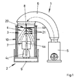
- Fig. 1 shows schematically a side view of an air cleaning device 1 for removing dust and / or dirt from an ambient air.
- the air cleaning device 1 comprises a housing 2, a cleaning device 3 with a filter device 4, a suction device 5, a conduit device 6 and an outlet device 7.
- the blower is fluidically connected to the housing 2 via a conduit means 6 formed as a flexible hose.
- the flexible hose extends from an outlet opening of the fan to an inlet opening located at the upper end side of the housing 2. In this case, the flexible hose terminates via an opening region with the inlet opening of the housing 2.
- the housing 2 comprises a cleaning device 3 which is fixed via a housing section and a filter device 4.
- the housing portion surrounds the filter device 4 and has a longitudinal axis, more precisely a vertical longitudinal axis.
- the filter device 4 in turn has a fluid supply pipe or riser 4a and a distributor nozzle device 20.
- the distributor nozzle device 20 is arranged at an upper end of the vertically arranged riser 4a, wherein the distributor nozzle device 20 preferably comprises a plurality of distributor nozzles 21, which are arranged in multiple stages, that is, one after the other.
- the exact design of the distributor nozzles 21 is in Fig. 2a and 2b shown in more detail and will be explained in connection with these drawings below.
- the last distributor nozzle 21 in the flow direction (of the medium) is secured against a vertical offset by a holding rod 8 integrated in the housing 2.
- the housing 2 has a bottom portion or a bottom. Together with the lower portion of the housing 2 thus a collecting container 9 is formed for a liquid medium.
- the liquid medium is conveyed via a feed pump 4c, which is connected to the riser 4a, through the riser 4a into the distributor nozzle device 20. From there, the medium exits through corresponding recesses and forms a curtain of atomized liquid medium. So that the distributor nozzle device 20 does not offset axially, the holding rod 8 in the housing 2 is formed directly above the distributor nozzle device 20.
- the dirty ambient air is passed through the suction device 5 through the conduit means 6 in the housing 2 by the cleaning device 4.
- the air to be cleaned passes through the curtain of atomized, liquid medium, whereby dirt particles are washed out. After the cleaning, the cleaned air is discharged through the outlet 7.
- the outlet 7 may also include a conduit means 6.
- Handles 10 are formed laterally on the housing 2 in order to simplify handling, in particular when transporting the air cleaning device 1.
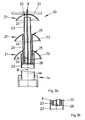
- FIG. 2a-b schematically show the distributor nozzle device 20 according to Fig. 1 in cross section, Fig. 2 a detail in detail, cut along the line AB according to Fig. 2a , laterally rotated by 90 ° Fig. 2a ,
- the distributor nozzle device 20 comprises three distributor nozzles 21, which each comprise an impact body 22 and a supply pipe line section 23.
- the baffles 22 are substantially plate-shaped or bell-shaped and have an impact surface 24 on their sides facing the respective feed pipe section 23.
- the baffle 24 is designed such that a liquid medium flowing out of an outlet opening 25 of the feed pipe section 23 onto the baffle 24 is deflected laterally.
- the baffle 24 is aligned inclined to a central axis M of the corresponding supply pipe section 23.
- the baffle 24 is approximately parabolic or bell-shaped.
- the distributor nozzles 21 are constructed in a similar way in principle and differ only slightly, for example in their dimensions.
- the supply pipe sections 23 are presently designed as circular cylindrical tubes, which accordingly have an outlet opening 25 with a circular flow cross-section.
- the material from which the supply pipe sections 23 may be a plastic, a metal, a metal alloy, stainless steel or the like, which may be coated, for example.
- the distributor nozzles 21 are arranged in multiple stages. That is, the distributor nozzles 21 are arranged in succession in the flow direction of the liquid medium, so that a plurality of medium curtains, preferably vertically offset from one another, can be produced.
- the supply pipe section 23 of a downstream distributor nozzle 21 protrudes into the supply pipe section 23 of the corresponding upstream distributor nozzle 21.
- the feed pipe sections 23 of the individual distributor nozzles 21 are correspondingly sized differently in the circumferential direction, in this case with a different diameter, wherein the external dimension of the downstream distributor nozzle 21 is smaller than the inside dimension of the upstream distributor nozzle 21.
- the difference between the external dimension of the downstream distributor nozzle 21 and the internal dimension the upstream distribution nozzle 21 is dimensioned such that a gap, in the present case an annular gap remains, through which the liquid medium can escape.
- the gap defines the resulting exit port for the liquid medium.
- the first distributor nozzle 21 in the flow direction that is, the first stage of the distributor nozzle device 20, is connected to the riser 4a.
- the corresponding connection regions of distributor nozzle 21 and riser 4a are formed so that they are sealingly connectable.
- the baffles 22 of the distribution nozzles 21 are respectively attached to the supply pipe portion 23 of the downstream distribution nozzle 21 except for the last distribution nozzle 21.
- the baffle 22 of the last distribution nozzle 21 in the flow direction, that is, the last stage of the distribution nozzle means 20 is fixed to a support rod 8 ,
- the support rod 8 protrudes with one end into the supply pipe section of the last distribution nozzle 21. With the other end, the support rod 8 is attached to a part of the air-cleaning device 1, preferably attached hinged.
- the supply pipe sections 23 of the distributing nozzles 21 are according to FIG Fig. 2a different lengths and open, with the exception of the supply pipe section 23 of the first distributor nozzle 21, in a common, designed as a holding web holder device 26.
- the respective ends of the supply pipe sections 23 are secured, so that an offset of the feed pipe sections 23 is prevented.
- the holding land is secured in the supply pipe section 23 of the first distribution nozzle 21.
- the supply pipe section 23 of the first distribution nozzle 21 is secured against misalignment via the connection with the riser 4a.
- the substantially as a hollow cylindrical, along the central or longitudinal axis M extending, present three distributor nozzles comprehensive distributor nozzle device 20 has distributed over its circumference openings or recesses 4b, through which the liquid medium is emitted.
- Fig. 2b shows a cross section of the distributor nozzle device 20, cut along the section line AB Fig. 2a , In this cross-section, the arrangement of the ends of the supply pipe sections 23 of the respective distributor nozzles 21 in the region of the holding device designed as a holding device 26 can be seen.
- the web has a parallelepiped shape and extends transversely through the supply pipe section 23 of the first distributor nozzle 21, wherein there is sufficient space for the liquid medium to flow past the holding web laterally.
- the holding web itself is connected to the support rod 8.
- Fig. 3a-d shows schematic representations of a housing 2.
- the housing is constructed substantially cylindrical and has a vertical longitudinal axis.
- the housing 2 is shown in a first side view.
- the housing 2 essentially has three areas: a bottom area 2a, a middle area 2b and an upper area 2c. These areas each have constant outer dimensions in the view, wherein the outer dimensions of the bottom portion 2 a to the upper portion 2 c are formed smaller, which increases the stability of the housing 2.
- Fig. 3b shows a longitudinal section through the housing 2, cut along the section line AA in Fig. 3a , Schematically here the riser 4a and the feed pump 4c is shown. Also clear is the double-tube structure of the housing with an inner tube 2d and an outer tube 2e. Laterally there is a blow-out, through which the purified air is discharged.
- the bottom portion 2a is formed as a collecting container 9, in which the liquid medium is collected and thus forms a reservoir.
- Fig. 3c shows the housing 2 in one of the in Fig. 2a Side view rotated by about 90 °.
- the blow-out opening formed in the central area 2b can clearly be seen for blowing out the cleaned air to the surroundings.
- Fig. 3d shows a longitudinal section of the housing 2 along the section line AA in Fig. 3c ,
- the bottom portion 2 a is formed as a collecting container 9.
- the feed pump 4c is fixed to a bottom of the housing 2 and fluidly connected to the riser 4a. Axially above the riser is integrated into the housing 2 holding rod 8 is formed, which prevents axial displacement of the distributor nozzle means (not shown) at the end of the riser 4a.
Landscapes
- Engineering & Computer Science (AREA)
- Chemical & Material Sciences (AREA)
- Combustion & Propulsion (AREA)
- Mechanical Engineering (AREA)
- General Engineering & Computer Science (AREA)
- Chemical Kinetics & Catalysis (AREA)
- Nozzles (AREA)
Applications Claiming Priority (1)
| Application Number | Priority Date | Filing Date | Title |
|---|---|---|---|
| DE202007009113U DE202007009113U1 (de) | 2007-06-28 | 2007-06-28 | Luft-Reinigungsvorrichtung |
Publications (1)
| Publication Number | Publication Date |
|---|---|
| EP2065082A1 true EP2065082A1 (fr) | 2009-06-03 |
Family
ID=39986462
Family Applications (1)
| Application Number | Title | Priority Date | Filing Date |
|---|---|---|---|
| EP08010573A Withdrawn EP2065082A1 (fr) | 2007-06-28 | 2008-06-11 | Dispositif de purification de l'air |
Country Status (2)
| Country | Link |
|---|---|
| EP (1) | EP2065082A1 (fr) |
| DE (1) | DE202007009113U1 (fr) |
Cited By (3)
| Publication number | Priority date | Publication date | Assignee | Title |
|---|---|---|---|---|
| DE102015012783A1 (de) * | 2015-10-05 | 2017-04-06 | Dräger Safety AG & Co. KGaA | Konditionierungsmodul zum Temperieren und Befeuchten eines strömenden Gases |
| CN111550877A (zh) * | 2020-05-11 | 2020-08-18 | 庄伙金 | 一种家用空气净化设备 |
| DE102020130767B3 (de) | 2020-11-20 | 2021-10-28 | Christopher Laubvogel | Gehäuse für wahlweise einen Luftreiniger- oder eine Saugeinrichtung und System zum Reinigen von Luft und zum Staubsaugen |
Citations (9)
| Publication number | Priority date | Publication date | Assignee | Title |
|---|---|---|---|---|
| NL60905C (fr) * | ||||
| GB103488A (en) * | 1915-11-26 | 1900-01-01 | Ullern & Cie Soc | Improvements in or relating to Spraying Devices. |
| GB204796A (en) * | 1922-07-13 | 1923-10-11 | Albert Edwin Burton | Improvements in or relating to devices for spraying oil and other fluids |
| DE551537C (de) * | 1930-09-27 | 1932-06-01 | Otto & Co Gmbh Dr C | Berieselungsvorrichtung fuer Hordenwaescher |
| US2314754A (en) * | 1941-07-25 | 1943-03-23 | Hudson Engineering Corp | Spray head |
| JPS63151328A (ja) * | 1986-12-13 | 1988-06-23 | Takeshi Mori | 空気浄化装置 |
| DE20302152U1 (de) | 2003-02-10 | 2003-05-08 | Staubfresser GmbH, 68542 Heddesheim | Luftreinigungsgebläse |
| WO2003070348A1 (fr) * | 2002-02-21 | 2003-08-28 | Shell Internationale Research Maatschappij B.V. | Appareil et procede permettant de traiter un fluide |
| EP1506805A1 (fr) | 2003-08-13 | 2005-02-16 | Klaus Kowalewski | Dispositif de purification d'air |
-
2007
- 2007-06-28 DE DE202007009113U patent/DE202007009113U1/de not_active Expired - Lifetime
-
2008
- 2008-06-11 EP EP08010573A patent/EP2065082A1/fr not_active Withdrawn
Patent Citations (9)
| Publication number | Priority date | Publication date | Assignee | Title |
|---|---|---|---|---|
| NL60905C (fr) * | ||||
| GB103488A (en) * | 1915-11-26 | 1900-01-01 | Ullern & Cie Soc | Improvements in or relating to Spraying Devices. |
| GB204796A (en) * | 1922-07-13 | 1923-10-11 | Albert Edwin Burton | Improvements in or relating to devices for spraying oil and other fluids |
| DE551537C (de) * | 1930-09-27 | 1932-06-01 | Otto & Co Gmbh Dr C | Berieselungsvorrichtung fuer Hordenwaescher |
| US2314754A (en) * | 1941-07-25 | 1943-03-23 | Hudson Engineering Corp | Spray head |
| JPS63151328A (ja) * | 1986-12-13 | 1988-06-23 | Takeshi Mori | 空気浄化装置 |
| WO2003070348A1 (fr) * | 2002-02-21 | 2003-08-28 | Shell Internationale Research Maatschappij B.V. | Appareil et procede permettant de traiter un fluide |
| DE20302152U1 (de) | 2003-02-10 | 2003-05-08 | Staubfresser GmbH, 68542 Heddesheim | Luftreinigungsgebläse |
| EP1506805A1 (fr) | 2003-08-13 | 2005-02-16 | Klaus Kowalewski | Dispositif de purification d'air |
Cited By (4)
| Publication number | Priority date | Publication date | Assignee | Title |
|---|---|---|---|---|
| DE102015012783A1 (de) * | 2015-10-05 | 2017-04-06 | Dräger Safety AG & Co. KGaA | Konditionierungsmodul zum Temperieren und Befeuchten eines strömenden Gases |
| US10046286B2 (en) | 2015-10-05 | 2018-08-14 | Dräger Safety AG & Co. KGaA | Conditioning module for regulating the temperature of and humidifying a flowing gas |
| CN111550877A (zh) * | 2020-05-11 | 2020-08-18 | 庄伙金 | 一种家用空气净化设备 |
| DE102020130767B3 (de) | 2020-11-20 | 2021-10-28 | Christopher Laubvogel | Gehäuse für wahlweise einen Luftreiniger- oder eine Saugeinrichtung und System zum Reinigen von Luft und zum Staubsaugen |
Also Published As
| Publication number | Publication date |
|---|---|
| DE202007009113U1 (de) | 2008-11-13 |
Similar Documents
| Publication | Publication Date | Title |
|---|---|---|
| EP1506805B1 (fr) | Dispositif de purification d'air | |
| DE102010031459A1 (de) | Diffusor für geringe Bauhöhe | |
| DE69715678T2 (de) | Verbesserte beimischvorrichtung mit belüfter | |
| WO2000010681A1 (fr) | Procede pour nettoyer des bougies d'un filtre a bougies | |
| EP3730022B1 (fr) | Élément filtrant | |
| EP1122338A2 (fr) | Appareil pour projeter des liquides de décapage ou de rinçage sur des objets métalliques | |
| DE1457299B2 (de) | Vorrichtung zum entfernen von teilchen aus einem verunreinigten gasfoermigen medium | |
| EP4045169A1 (fr) | Dispositif de filtre et procédé de nettoyage d'un élément de filtre d'un dispositif de filtre | |
| DE19544074C2 (de) | Automatisch arbeitende Reinigungsanlage für Werkstücke | |
| DE19637086A1 (de) | Automatisch arbeitende Reinigungsanlage für Werkstücke | |
| EP1967296B1 (fr) | Dispositif de nettoyage de caisses et sol correspondant | |
| DE19531421A1 (de) | Injektor-Vorrichtung zur Pulver-Sprühbeschichtung | |
| DE1287042B (de) | Gaswaescher | |
| DE202007009113U1 (de) | Luft-Reinigungsvorrichtung | |
| EP0958977B1 (fr) | Installation de nettoyage pour carosserie de véhicules | |
| AT522780B1 (de) | Vorrichtung zur reinigung von gas | |
| DE1948379C3 (de) | Vorrichtung zum Reinigen von Luft | |
| EP1344560A2 (fr) | Dispositif pour traiter un milieux gazeux, en particulier pour nettoyer l'air sortant ou alimentant un bâtiment | |
| EP2827968B1 (fr) | Elément de filtre doté d'une unité de nettoyage pour grands débits volumiques | |
| DE2902461A1 (de) | Vorrichtung zum reinigen von gas | |
| DE1671393C3 (de) | Naß-Wascher | |
| DE20121272U1 (de) | Vorrichtung, insbesondere Werkstatt- und/oder Hobbysystem zum Bearbeiten, insbesondere Vakuumsaugstrahlen, von Flächen | |
| DE202006013292U1 (de) | Luft-Reinigungsvorrichtung | |
| DE1778261C3 (de) | Vorrichtung zum Abziehen von Farbe aus der Luft in einem Farbspritzstand | |
| DE2842651A1 (de) | Belueftungsvorrichtung |
Legal Events
| Date | Code | Title | Description |
|---|---|---|---|
| PUAI | Public reference made under article 153(3) epc to a published international application that has entered the european phase |
Free format text: ORIGINAL CODE: 0009012 |
|
| AK | Designated contracting states |
Kind code of ref document: A1 Designated state(s): AT BE BG CH CY CZ DE DK EE ES FI FR GB GR HR HU IE IS IT LI LT LU LV MC MT NL NO PL PT RO SE SI SK TR |
|
| AX | Request for extension of the european patent |
Extension state: AL BA MK RS |
|
| AKX | Designation fees paid | ||
| STAA | Information on the status of an ep patent application or granted ep patent |
Free format text: STATUS: THE APPLICATION IS DEEMED TO BE WITHDRAWN |
|
| 18D | Application deemed to be withdrawn |
Effective date: 20090904 |
|
| REG | Reference to a national code |
Ref country code: DE Ref legal event code: 8566 |