EP2065100A1 - Trennmittelsprühvorrichtung für eine Giessmaschine - Google Patents
Trennmittelsprühvorrichtung für eine Giessmaschine Download PDFInfo
- Publication number
- EP2065100A1 EP2065100A1 EP08020282A EP08020282A EP2065100A1 EP 2065100 A1 EP2065100 A1 EP 2065100A1 EP 08020282 A EP08020282 A EP 08020282A EP 08020282 A EP08020282 A EP 08020282A EP 2065100 A1 EP2065100 A1 EP 2065100A1
- Authority
- EP
- European Patent Office
- Prior art keywords
- release agent
- spray
- dosing
- nozzle
- spray nozzle
- Prior art date
- Legal status (The legal status is an assumption and is not a legal conclusion. Google has not performed a legal analysis and makes no representation as to the accuracy of the status listed.)
- Granted
Links
Images


Classifications
-
- B—PERFORMING OPERATIONS; TRANSPORTING
- B22—CASTING; POWDER METALLURGY
- B22D—CASTING OF METALS; CASTING OF OTHER SUBSTANCES BY THE SAME PROCESSES OR DEVICES
- B22D17/00—Pressure die casting or injection die casting, i.e. casting in which the metal is forced into a mould under high pressure
- B22D17/20—Accessories: Details
- B22D17/2007—Methods or apparatus for cleaning or lubricating moulds
-
- B—PERFORMING OPERATIONS; TRANSPORTING
- B05—SPRAYING OR ATOMISING IN GENERAL; APPLYING FLUENT MATERIALS TO SURFACES, IN GENERAL
- B05B—SPRAYING APPARATUS; ATOMISING APPARATUS; NOZZLES
- B05B12/00—Arrangements for controlling delivery; Arrangements for controlling the spray area
- B05B12/02—Arrangements for controlling delivery; Arrangements for controlling the spray area for controlling time, or sequence, of delivery
-
- B—PERFORMING OPERATIONS; TRANSPORTING
- B05—SPRAYING OR ATOMISING IN GENERAL; APPLYING FLUENT MATERIALS TO SURFACES, IN GENERAL
- B05B—SPRAYING APPARATUS; ATOMISING APPARATUS; NOZZLES
- B05B12/00—Arrangements for controlling delivery; Arrangements for controlling the spray area
- B05B12/08—Arrangements for controlling delivery; Arrangements for controlling the spray area responsive to condition of liquid or other fluent material to be discharged, of ambient medium or of target ; responsive to condition of spray devices or of supply means, e.g. pipes, pumps or their drive means
- B05B12/085—Arrangements for controlling delivery; Arrangements for controlling the spray area responsive to condition of liquid or other fluent material to be discharged, of ambient medium or of target ; responsive to condition of spray devices or of supply means, e.g. pipes, pumps or their drive means responsive to flow or pressure of liquid or other fluent material to be discharged
- B05B12/087—Flow or presssure regulators, i.e. non-electric unitary devices comprising a sensing element, e.g. a piston or a membrane, and a controlling element, e.g. a valve
- B05B12/088—Flow or presssure regulators, i.e. non-electric unitary devices comprising a sensing element, e.g. a piston or a membrane, and a controlling element, e.g. a valve the sensing element being a flexible member, e.g. membrane, diaphragm, bellows
-
- B—PERFORMING OPERATIONS; TRANSPORTING
- B05—SPRAYING OR ATOMISING IN GENERAL; APPLYING FLUENT MATERIALS TO SURFACES, IN GENERAL
- B05B—SPRAYING APPARATUS; ATOMISING APPARATUS; NOZZLES
- B05B7/00—Spraying apparatus for discharge of liquids or other fluent materials from two or more sources, e.g. of liquid and air, of powder and gas
- B05B7/02—Spray pistols; Apparatus for discharge
- B05B7/12—Spray pistols; Apparatus for discharge designed to control volume of flow, e.g. with adjustable passages
- B05B7/1254—Spray pistols; Apparatus for discharge designed to control volume of flow, e.g. with adjustable passages the controlling means being fluid actuated
- B05B7/1263—Spray pistols; Apparatus for discharge designed to control volume of flow, e.g. with adjustable passages the controlling means being fluid actuated pneumatically actuated
-
- B—PERFORMING OPERATIONS; TRANSPORTING
- B05—SPRAYING OR ATOMISING IN GENERAL; APPLYING FLUENT MATERIALS TO SURFACES, IN GENERAL
- B05B—SPRAYING APPARATUS; ATOMISING APPARATUS; NOZZLES
- B05B9/00—Spraying apparatus for discharge of liquids or other fluent material, without essentially mixing with gas or vapour
- B05B9/03—Spraying apparatus for discharge of liquids or other fluent material, without essentially mixing with gas or vapour characterised by means for supplying liquid or other fluent material
- B05B9/04—Spraying apparatus for discharge of liquids or other fluent material, without essentially mixing with gas or vapour characterised by means for supplying liquid or other fluent material with pressurised or compressible container; with pump
- B05B9/0403—Spraying apparatus for discharge of liquids or other fluent material, without essentially mixing with gas or vapour characterised by means for supplying liquid or other fluent material with pressurised or compressible container; with pump with pumps for liquids or other fluent material
- B05B9/0413—Spraying apparatus for discharge of liquids or other fluent material, without essentially mixing with gas or vapour characterised by means for supplying liquid or other fluent material with pressurised or compressible container; with pump with pumps for liquids or other fluent material with reciprocating pumps, e.g. membrane pump, piston pump, bellow pump
-
- B—PERFORMING OPERATIONS; TRANSPORTING
- B05—SPRAYING OR ATOMISING IN GENERAL; APPLYING FLUENT MATERIALS TO SURFACES, IN GENERAL
- B05B—SPRAYING APPARATUS; ATOMISING APPARATUS; NOZZLES
- B05B9/00—Spraying apparatus for discharge of liquids or other fluent material, without essentially mixing with gas or vapour
- B05B9/03—Spraying apparatus for discharge of liquids or other fluent material, without essentially mixing with gas or vapour characterised by means for supplying liquid or other fluent material
- B05B9/04—Spraying apparatus for discharge of liquids or other fluent material, without essentially mixing with gas or vapour characterised by means for supplying liquid or other fluent material with pressurised or compressible container; with pump
Definitions
- the invention relates to a release agent spray device for a casting machine according to the preamble of claim 1.
- release agent spray devices are used, for example, as release agent spray systems for the automated spraying of casting molds in die casting machines.
- release agent spray systems for the automated spraying of casting molds in die casting machines.
- the amount of release agent discharged per spray depends, among other things, on the settable stroke of the control piston and its opening time during which it releases the release agent supply line. Because of the additional dependence on other parameters, such as release agent pressure, geometry and in particular cross section of the spray nozzle and pressure and duration of the spray nozzle supplied and the release agent sucking spray air pulse, sprayed per spray and spray release agent amount is not well known in these conventional spray systems and will not exactly given.
- the spray characteristics and especially the sprayed release agent amount should not be affected by any switching delays system components involved, such as shut-off valves and the like.
- the sprayed amount of release agent should be kept to a minimum.
- the invention is based on the technical problem of providing a release agent spraying device of the type mentioned, which allows reliable discharge of a predetermined amount of release agent in a respective spray over one or more spray nozzles.
- the invention solves this problem by providing a release agent spray device having the features of claim 1.
- the discharge means comprise at least one metering unit which is associated with at least one spray nozzle and determines a release agent to be discharged in a pending spray through the at least one associated spray nozzle and separated from a release agent supply for discharge in the upcoming spray provides.
- release agent spraying device With this release agent spraying device according to the invention, comparatively small quantities of release agent can also be precisely metered and discharged per spray, even with low spraying times and / or low release agent pressure and / or relatively small nozzle cross section.
- the amount of release agent defined by the pending dosing dosage unit is provided separately from a release agent supply, such as a supply of release agent from a release agent source via a release agent supply line, and may be discharged in the upcoming spray without being of varying and / or uncertainty
- System parameters is influenced, such as release agent pressure, nozzle geometry and pressure curve and duration of the spray nozzle respectively supplied spray air.
- the exact discharge of the desired amount of release agent per spray is not affected by any switching delays or other not more accurately known or reproducible performance characteristics of participating system components, such as valves, control pistons and the like, even at very short spraying times.
- the respective dosing unit comprises a release agent space which is shut off via a release agent supply line with a release agent source and a nozzle connection line with the at least one associated spray nozzle, and a movable and thereby the release agent space with variable volume limiting dosing.
- this measure is according to claim 3 depending on a check valve in the release agent supply line and / or the nozzle connection line.
- These automatic valve control means permit the desired delivery of release agent into the release agent space prior to the next spray and delivery of the amount of release agent stored there through the one or more associated spray nozzles in the next spray without release agent returning from the release agent space to the release agent supply line or release agent source.
- the metering element is together with at least one of the one or more associated with him spray nozzles in a common housing body, so that the metering element can be installed with the relevant spray nozzle as a structural unit.
- the metering unit has a control medium space connected to a control medium source via which the metering element can be controlled.
- the control medium source may comprise means for controlled pressurization of the metering element with at least two different control pressures, wherein a first control pressure controls the metering for metering release agent in the release agent and a different from the first second control pressure the metering for discharging the metered release agent activates the release agent space.
- the discharge means are adapted to be discharged in the next spray and / or different dosing units release agent amount variable adjust.
- release agent amount variable adjust if necessary, different amounts of release agent can be sprayed in successive sprays on the same spray nozzle or different amounts of release agent in parallel sprays via spray nozzles, which are assigned to different metering units.
- an adjustable movement limiter for the variable adjustment of the amount of release agent metered into the release agent space or discharged therefrom is assigned to the metering element of the respective metering unit.
- the release agent spray device shown with its presently interesting components is suitable, for example, for the automated spraying of mold surfaces in die casting machines, for example for metal diecasting, with a conventional release agent or separation medium.
- the release agent spray device includes one or more spray nozzles as needed, of which in the views of Fig. 1 and 2 a spray nozzle 1 is shown representatively.
- the respective spray nozzle 1 is mounted on a spray side 2a of a spray block or housing body 2, in which also one or more metering units are provided, of which in the view of Fig. 1 and 2 one of the spray nozzle 1 associated dosing unit 3 is shown representatively.
- the dosing unit 3 shown includes a hollow chamber 4 provided in the housing body 2 which is divided into a separating agent space 6 and a control medium space 7 by a dosing piston 5 which acts as a dosing element and is arranged to be axially movable.
- the control medium space 7 is connected by a control medium line 8 to a conventional control medium source, not shown.
- the control medium chamber 7 can optionally be pressure-loaded or depressurized.
- the release agent space 6 is connected by a release agent supply line 9 with a conventional, not shown release agent source.
- a check valve 10 is arranged so that release agent can be conveyed from the release agent source in the release agent space 6, a release agent reflux from the release agent space 6 to the release agent source is blocked.
- the spray nozzle 1 is connected via a nozzle connection line 11 with the release agent space 6, wherein in the nozzle connection line 11, a check valve 12 is arranged such that release agent can be conveyed from the release agent space 6 to the spray nozzle 1, however, a backflow into the release agent space 6 is blocked.
- a spray carrier medium line 13 the spray nozzle 1 is connected to a conventional, not shown Sprühamediumquelle to the spray nozzle 1, a spray carrier medium, such as. Compressed air to be able to perform, with which the spraying of the parallel supplied liquid release agent is effected.
- suitable geometric design of the spray nozzle 1 with associated nozzle channels 1a results in a conventional manner mixing of the spray carrier medium, e.g. Air, with the release agent and the desired spray effect.
- a piston stem 15 departing from the metering piston 5 is sealed in a bore 16, which is introduced into the housing body 2 from the spray side 2 a.
- an adjusting screw 17 is screwed in from the outside, which acts with a stop 17a as a variably adjustable Kolbenhubbegrenzer.
- a coil spring 18 On the opposite side of the metering piston 5 is supported on a coil spring 18, which in turn is supported on a bottom surface 19 of the release agent space 6 and secured by a piston stem stub 20 against lateral displacement.
- one dosing unit can each be assigned individually to a spray nozzle, ie in this case only one spray nozzle is connected to the release agent space of the respective dosing unit.
- several spray nozzles may be coupled in parallel to a dosing unit.
- a dosing unit and its associated spray nozzle can also be integrated into a common spray block module body, as shown, to modularly build an entire spray system from a plurality of spray block modules, or alternatively all or at least several Dosing units integrated with their coupled spray nozzles in a spray block.
- these can be constructed the same or different, for example, several metering units can be provided with the same or different cross-section of the release agent space, each of which is assigned an individually definable number of spray nozzles.
- the discharge means used in the Trennffensprühvoroplasty invention comprise, in addition to the above-mentioned components, in particular the metering unit (s) and the associated medium lines or medium channels, depending on the application, further system components, which are conventional and therefore not shown and explained in detail here.
- the discharge means comprise a suitable spray control unit for controlling the device components involved. It is understood that a suitable control algorithm is implemented in this control unit in order to carry out the release agent spraying method according to the invention, as described in more detail below.
- the release agent spray device By means of its special discharge means for the controlled spray discharge of the release agent from the respective spray nozzle 1 using the characteristic dosing unit (s) 3, the release agent spray device according to the invention enables the discharge of a very precisely determinable amount of release agent per spray stroke, before a respective spray burst Release agent is sucked from the metering piston 5 in the release agent space 6, which is then pressed at the next spray from the metering piston 5 to the one or more coupled spray nozzles 1 and discharged or sprayed on this.
- Fig. 1 the operating state when sucking release agent.
- the control fluid chamber 7 is depressurized by discharging control medium via the control medium line 8, so that the metering piston 5 due to the pressure force of the coil spring 18 and / or a negative pressure in the control fluid chamber 7 in Fig. 1
- release agent flows from the release agent source into the release agent space 6 via the release agent supply line 9 and the opening non-return valve 10, the check valve 12 remaining closed in the nozzle connection line 11.
- the sucked release agent quantity is thus accurately determined by the intake stroke of the metering 5.
- This can be defined by a stop 5a provided on the metering piston 5 at an in Fig. 1 Upper boundary surface of the control medium space 7 comes to rest.
- a limitation of the intake stroke of the metering 5 may be provided, ie in the corresponding end position of the metering 5, the pressure force of the coil spring 18 has up to the value of a predetermined remaining pressure force of the control medium on the metering 5 removed.
- the subsequent spraying process can be initiated, as in Fig. 2 is illustrated.
- the control medium pressure in the control medium chamber 7 is increased sufficiently, so that the metering piston 5 in the direction of reduction of the release agent space 6, ie in Fig. 2 down, against the force of the compression spring 18 moves.
- the check valve 12 opens in the nozzle connection line 11, so that release agent is conveyed from the release agent chamber 6 via the nozzle connection line 11 to the spray nozzle 1, while the check valve 10 closes in the release agent supply line 9 and prevents a release agent backflow to the release agent source.
- the movement of the metering piston 5 is in the Fig. 1 and 2 symbolized by a movement arrow D, the release agent flow through a respective flow arrow T.
- the spray nozzle 1 sprays the supplied release agent in a spray 21, wherein the spray jet 21 a desired characteristic by appropriate design of the spray nozzle 1 and supply of the Release agent and the spray carrier medium can be adjusted, eg in geometry and direction, also variable if required.
- the spray nozzle 1 can be designed for this purpose in a conventional manner to internal or external mixing principles.
- the end of the discharge movement of the metering piston 5 in the respective spray is defined by striking the Kolbenhubbegrenzers 17 a of the screw 17 on the spray side 2 a of the housing body 2. This end position is in Fig. 2 shown.
- this end position of the metering piston 5 can be variably adjusted.
- any other piston stroke limiting measure known per se to the person skilled in the art can be provided.
- the maximum or compressed state of the helical compression spring 18 that can be determined by the discharge control pressure of the control medium can define such an alternative end stop or another conventional, unchanging one in the release agent space 6 or variably internally or remotely controlled externally adjustable end stop.
- very small quantities of release agent can thus be precisely determined for each individual spray, stored in the release agent space 6 and sprayed in the spray concerned.
- the amount of release agent to be discharged in the respective spray can be fixed variably or as explained, depending on the system design.
- the amount of release agent can also be variably set for successive sprays of the same spray nozzle, and / or different amounts of release agent can be specified for different spray nozzles.
- the discharge of the defined predetermined amount of release agent in the respective spray is separated from the release agent supply from the release agent source, i. decoupled.
- the 3 and 4 illustrate a variant of the in the Fig. 1 and 2 shown Trennffensprühvorraum, wherein identical or functionally equivalent components are provided with the same reference numerals and in this respect to the above explanations of Trennstoffsprühvortechnisch the Fig. 1 and 2 can be referenced.
- the release agent spray device according to the 3 and 4 is different from the one of Fig. 1 and 2 in a modified metering unit 3 '. In this dosing unit 3 ', an annular metering membrane 5' assumes the function of the metering piston 5 in the release agent spraying device Fig.
- the Dosiermembran 5 is with its outer edge on the housing body 2 fixed in a fluid-tight manner, while it is fixed in its central region on an axially movable diaphragm control pin 15 '.
- the membrane 5 ' has a central opening through which the membrane control pin 15' extends.
- the membrane control pin 15 ' is a membrane holding part 22 with an annular nip, in which the membrane 5' is held fluid-tight with its central opening edge.
- the diaphragm control pin 15 ' has the respective components as shown and functions such as the piston shaft 15 in the embodiment of FIGS Fig. 1 and 2 , so that in turn to the corresponding above explanations to the Fig. 1 and 2 can be referenced.
- the hollow chamber 4 is formed by an inner portion of smaller diameter of a two-stage bore in the housing body 2, wherein the inner part passes to form an annular shoulder in an outer part of larger diameter.
- the membrane 5 ' is placed with its outer edge on the annular shoulder and is clamped there fluid-tight by a closure piece 23 which is fluid-tightly inserted into the outer bore part.
- the closure piece 23 simultaneously forms the guide for the membrane control pin by extending through a central bore of the closure piece 23, wherein an annular seal for sealing the annular gap between diaphragm control pin 15 'and closure piece 23 is provided.
- the Dosiermembran 5 'held clamped in such a way acts according to the metering piston 5 in the embodiment of Fig. 1 and 2 as a separation element for dividing the hollow chamber 4 into the separating agent space 6 and the control medium space 7.
- the axial movement of the membrane holding bolt 15 ' moves the dosing membrane 5' between the in Fig. 3 shown, folded membrane position with a larger volume of the release agent space 6 and in Fig. 4 shown, bulging Membrane position with a smaller volume of the release agent space 6.
- the movement of membrane 5 'and diaphragm control pin 15' between these two end positions takes place as in the embodiment of Fig.
- Fig. 3 thus corresponds analogously to Fig. 1 the operating state during the suction of release agent, while Fig. 4 analogous to Fig. 2 represents the spraying process.
- Fig. 4 analogous to Fig. 2 represents the spraying process.
- the functionality is completely identical to that of the example of Fig. 1 and 2 Reference may be made to their above explanations.
- This also applies to the design and function of the means of setting the two in the 3 and 4 and shown for the variable setting of discharged in each spray release agent amount by adjusting the screw 17, which acts here with its stop 17a as a variably adjustable stroke limiter for the diaphragm control pin 15 '.
- FIGS. 5 and 6 illustrate another variant of the in the Figures 1 and 2 Trennstoffsprühvorraum shown, again identical or functionally equivalent components are provided with the same reference numerals and in this respect to the above explanations of Trennstoffsprühvortechnisch the Figures 1 and 2 can be referenced.
- the release agent spray device according to the FIGS. 5 and 6 is different from the one of Figures 1 and 2 in that instead of the check valves a media-controlled 3/2-way valve 24 is provided, to which the separating agent supply line 9 and the nozzle connection line 11 are suitably coupled, as shown.
- the coupling is chosen so that the valve 24 when in FIG. 5 shown suction forming a valve passage 25 for the release agent supply line 9, so that via the release agent supply line 9 release agent can be sucked into the release agent space 6, and that it simultaneously breaks the connection from the release agent space 6 to the nozzle connection line 11.
- the valve 24 separates the release agent supply line 9 and thereby blocks the connection between the release agent space 6 and release agent source, while it provides a valve passage 26 for the nozzle connection 11, so that release agent from the release agent chamber 6 via the nozzle connection line 11 to the spray nozzle 1 and promoted from this is sprayed.
- valve 24 between its two shown positions in the intake of FIG. 5 on the one hand and in spray mode of FIG. 6
- media-controlled by the release agent itself including the two valve branch lines 24a, 24b are provided.
- the intake operation creates a negative pressure in the branch line 24b relative to the release agent supply line 9 and the associated branch line 24a, whereby the valve 24 in its in FIG. 5 shown switching position is maintained, while in the spraying operation, a release agent overpressure in the branch line 24b is present, through which the valve 24 in its in FIG. 6 shown switching position is held.
- the invention makes it possible to retrofit conventional release agent spray devices quite simply, since the spray nozzles conventionally used can be used unchanged and only the respective metering unit assigned to a single or a group of several spray nozzles and an activation thereof must be additionally provided. All other conventional system components such as release agent source, control medium source, and spray medium source, as well as the associated control components, can be maintained virtually unchanged.
Landscapes
- Engineering & Computer Science (AREA)
- Mechanical Engineering (AREA)
- Casting Devices For Molds (AREA)
- Nozzles (AREA)
- Moulds For Moulding Plastics Or The Like (AREA)
Abstract
Description
- Die Erfindung bezieht sich auf eine Trennmittelsprühvorrichtung für eine Gießmaschine nach dem Oberbegriff des Anspruchs 1.
- Derartige Trennmittelsprühvorrichtungen werden beispielsweise als Trennmittelsprühsysteme zum automatisierten Besprühen von Gießformen in Druckgießmaschinen eingesetzt. Mit fortschreitenden Anforderungen an Gussqualität, Standzeiten, Wartung, Materialverbrauch und Umweltschutz steigen entsprechend die Anforderungen an die Trennmittelsprühsysteme.
- Es ist bekannt, das Trennmittel über eine oder mehrere Sprühdüsen in intermittierenden Sprühstößen auszutragen, indem eine zur jeweiligen Sprühdüse führende, absperrbare Trennmittelzufuhrleitung nur für einen gewissen Zeitraum während des Sprühstoßes geöffnet und der Sprühdüse gleichzeitig Druckluft zugeführt wird, so dass Trennmittel in die Sprühdüse gesaugt und von ihr druckluftunterstützt als Sprühstahl ausgetragen wird. Die Offenlegungsschrift
DE 32 38 201 A1 und die PatentschriftEP 1 468 745 B1 offenbaren derartige Trennmittelsprühvorrichtungen, bei denen zum steuerbaren Öffnen und Absperren der Trennmittelzufuhrleitung zur Sprühdüse ein durch Steuerluft betätigbarer Steuerkolben vorgesehen ist. Dadurch ist die Menge an pro Sprühstoß ausgetragenem Trennmittel unter anderem vom einstellbaren Hub des Steuerkolbens und von dessen Öffnungszeit abhängig, während der er die Trennmittelzufuhrleitung freigibt. Wegen der zusätzlichen Abhängigkeit von weiteren Parametern, wie Trennmitteldruck, Geometrie und insbesondere Querschnitt der Sprühdüse sowie Druck und Zeitdauer des der Sprühdüse zugeführten und das Trennmittel ansaugenden Sprühluftstoßes, ist die pro Sprühstoß und Sprühdüse versprühte Trennmittelmenge bei diesen herkömmlichen Sprühsystemen nicht genau bekannt und wird auch nicht genau vorgegeben. - Zur Erzielung kurzer Zykluszeiten im Gießprozess werden für moderne Druckgießmaschinen entsprechend schnelle Trennmittelsprühsysteme und demgemäß sehr kurze Sprühzeiten bei gleichbleibend guter, reproduzierbarer Sprühcharakteristik gefordert. Insbesondere sollte die Sprühcharakteristik und speziell die versprühte Trennmittelmenge auch nicht von etwaigen Schaltverzögerungen beteiligter Systemkomponenten, wie Absperrventilen und dgl., beeinflusst sein. Außerdem sollte die versprühte Trennmittelmenge minimal gehalten werden.
- Der Erfindung liegt als technisches Problem die Bereitstellung einer Trennmittelsprühvorrichtung der eingangs genannten Art zugrunde, die ein zuverlässiges Austragen einer vorgebbaren Trennmittelmenge in einem jeweiligen Sprühstoß über eine oder mehrere Sprühdüsen ermöglicht.
- Die Erfindung löst dieses Problem durch die Bereitstellung einer Trennmittelsprühvorrichtung mit den Merkmalen des Anspruchs 1. Bei dieser Trennmittelsprühvorrichtung beinhalten die Austragmittel wenigstens eine Dosiereinheit, die wenigstens einer Sprühdüse zugeordnet ist und eine in einem anstehenden Sprühstoß durch die wenigstens eine zugeordnete Sprühdüse auszutragende Trennmittelmenge festlegt und von einer Trennmittelzufuhr separiert zum Austragen im anstehenden Sprühstoß bereitstellt.
- Mit dieser erfindungsgemäßen Trennmittelsprühvorrichtung lassen sich pro Sprühstoß auch vergleichsweise geringe Trennmittelmengen exakt dosieren und austragen, auch bei geringen Sprühzeiten und/oder geringem Trennmitteldruck und/oder verhältnismäßig geringem Düsenquerschnitt. Die von der Dosiereinheit für den anstehenden Sprühstoß definiert festgelegte Trennmittelmenge wird separat von einer Trennmittelzufuhr, wie einer Zufuhr von Trennmittel aus einer Trennmittelquelle über eine Trennmittelzufuhrleitung, bereitgestellt und kann im anstehenden Sprühstoß ausgetragen werden, ohne dass sie von sich verändernden und/oder nicht genau bekannten Systemparametern beeinflusst wird, wie Trennmitteldruck, Düsengeometrie sowie Druckverlauf und Zeitdauer des der Sprühdüse jeweils zugeführten Sprühluftstoßes. Das exakte Austragen der gewünschten Trennmittelmenge pro Sprühstoß wird auch bei sehr kurzen Sprühzeiten nicht durch etwaige Schaltverzögerungen oder andere nicht genauer bekannte oder reproduzierbare Funktionscharakteristika beteiligter Systemkomponenten, wie Ventile, Steuerkolben und dergleichen, beeinflusst.
- In einer Weiterbildung der Erfindung nach Anspruch 2 umfasst die jeweilige Dosiereinheit einen Trennmittelraum, der absperrbar über eine Trennmittelzufuhrleitung mit einer Trennmittelquelle und über eine Düsenanschlussleitung mit der wenigstens einen zugeordneten Sprühdüse verbunden ist, und ein bewegliches und dadurch den Trennmittelraum mit variablem Volumen begrenzendes Dosierelement. Auf diese Weise kann die im anstehenden Sprühstoß über die eine oder mehreren zugeordneten Sprühdüsen auszutragende Trennmittelmenge in dem Trennmittelraum bevorratet werden, von wo sie dann im anstehenden Sprühstoß ausgetragen werden kann.
- In weiterer Ausgestaltung dieser Maßnahme befindet sich gemäß Anspruch 3 je ein Rückschlagventil in der Trennmittelzufuhrleitung und/oder der Düsenanschlussleitung. Diese selbsttätigen Ventilsteuermittel ermöglichen das gewünschte Zuführen von Trennmittel in den Trennmittelraum vor dem nächsten Sprühstoß und das Austragen der dort bevorrateten Trennmittelmenge über die eine oder mehreren zugeordneten Sprühdüsen im nächsten Sprühstoß, ohne dass Trennmittel aus dem Trennmittelraum in die Trennmittelzufuhrleitung bzw. die Trennmittelquelle zurückgelangt. In einer weiteren Ausgestaltung gemäß Anspruch 4 befindet sich das Dosierelement zusammen mit wenigstens einer der einen oder mehreren ihm zugeordneten Sprühdüsen in einem gemeinsamen Gehäusekörper, so dass das Dosierelement mit der betreffenden Sprühdüse als eine Baueinheit verbaut werden kann.
- In einer weiteren Ausgestaltung weist gemäß Anspruch 5 die Dosiereinheit einen mit einer Steuermediumquelle verbundenen Steuermediumraum auf, über den das Dosierelement gesteuert werden kann. In Weiterbildung gemäß Anspruch 6 kann die Steuermediumquelle Mittel zum gesteuerten Beaufschlagen des Dosierelements mit wenigstens zwei unterschiedlichen Steuerdrücken aufweisen, wobei ein erster Steuerdruck das Dosierelement zum Zudosieren von Trennmittel in den Trennmittelraum ansteuert und ein vom ersten verschiedener zweiter Steuerdruck das Dosierelement zum Austragen des zudosierten Trennmittels aus dem Trennmittelraum ansteuert.
- In Weiterbildung der Erfindung nach Anspruch 7 sind die Austragmittel dafür eingerichtet, die im jeweils nächsten Sprühstoß und/oder von unterschiedlichen Dosiereinheiten auszutragende Trennmittelmenge variabel einzustellen. So können bei Bedarf über die gleiche Sprühdüse unterschiedliche Trennmittelmengen in aufeinander folgenden Sprühstößen versprüht werden oder in parallelen Sprühstößen unterschiedliche Trennmittelmengen über Sprühdüsen, die verschiedenen Dosiereinheiten zugeordnet sind.
- In einer weiteren Ausgestaltung dieser Maßnahme ist gemäß Anspruch 8 dem Dosierelement der jeweiligen Dosiereinheit ein verstellbarer Bewegungsbegrenzer zur variablen Einstellung der in den Trennmittelraum zudosierten bzw. aus diesem ausgetragenen Trennmittelmenge zugeordnet. Dies stellt eine vorteilhaft einfache Maßnahme zum variablen Einstellen der pro Sprühstoß auszutragenden Trennmittelmenge dar.
- Vorteilhafte Ausführungsformen der Erfindung sind in den Zeichnungen dargestellt und werden nachfolgend beschrieben. Hierbei zeigen:
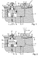
- Fig. 1
- eine schematische, ausschnittweise Querschnittansicht eines Sprühblocks einer Trennmittelsprühvorrichtung mit einem Dosierkolben als Dosierelement und einem Rückschlagventil für eine Druckgießmaschine in einer Zudosiersituation,
- Fig. 2
- eine Querschnittansicht entsprechend
Fig. 1 in einer Austragsituation der Sprühvorrichtung, - Fig. 3
- eine Querschnittansicht entsprechend
Fig. 1 für eine Variante mit Dosiermembran als Dosierelement, - Fig. 4
- eine Querschnittansicht entsprechend
Fig. 2 für die Variante mit Dosiermembran, - Fig. 5
- eine Querschnittansicht entsprechend
Fig. 1 für eine Variante mit einem Wegeventil statt dem Rückschlagventil und - Fig. 6
- eine Querschnittansicht entsprechend
Fig. 2 für die Variante vonFig. 5 . - Die in den
Fig. 1 und 2 mit ihren vorliegend interessierenden Komponenten gezeigte Trennmittelsprühvorrichtung eignet sich beispielsweise zum automatisierten Besprühen von Formoberflächen bei Druckgießmaschinen, z.B. für Metalldruckguss, mit einem üblichen Trennmittel bzw. Trennmedium. Die Trennmittelsprühvorrichtung beinhaltet je nach Bedarf eine oder mehrere Sprühdüsen, von denen in den Ansichten derFig. 1 und 2 eine Sprühdüse 1 repräsentativ gezeigt ist. Die jeweilige Sprühdüse 1 ist an einer Sprühseite 2a eines Sprühblocks bzw. Gehäusekörpers 2 montiert, in welchem außerdem eine oder mehrere Dosiereinheiten vorgesehen sind, von denen in der Ansicht derFig. 1 und 2 eine der gezeigten Sprühdüse 1 zugeordnete Dosiereinheit 3 repräsentativ gezeigt ist. - Die gezeigte Dosiereinheit 3 beinhaltet eine im Gehäusekörper 2 vorgesehene Hohlkammer 4, die durch einen als Dosierelement fungierenden, axial beweglich angeordneten Dosierkolben 5 in einen Trennmittelraum 6 und einen Steuermediumraum 7 aufgeteilt ist. Der Steuermediumraum 7 ist durch eine Steuermediumleitung 8 mit einer üblichen, nicht gezeigten Steuermediumquelle verbunden. Durch Zufuhr oder Abfuhr von Druckluft oder eines anderen gasförmigen oder flüssigen Steuermediums kann der Steuermediumraum 7 wahlweise druckbelastet oder druckentlastet werden. Der Trennmittelraum 6 ist durch eine Trennmittelzufuhrleitung 9 mit einer üblichen, nicht gezeigten Trennmittelquelle verbunden. In der Trennmittelzufuhrleitung 9 ist ein Rückschlagventil 10 so angeordnet, dass Trennmittel von der Trennmittelquelle in den Trennmittelraum 6 gefördert werden kann, ein Trennmittelrückfluss vom Trennmittelraum 6 zur Trennmittelquelle jedoch blockiert wird.
- Die Sprühdüse 1 ist über eine Düsenanschlussleitung 11 mit dem Trennmittelraum 6 verbunden, wobei in der Düsenanschlussleitung 11 ein Rückschlagventil 12 derart angeordnet ist, dass Trennmittel aus dem Trennmittelraum 6 zur Sprühdüse 1 gefördert werden kann, ein Rückfluss in den Trennmittelraum 6 jedoch blockiert wird. Über eine Sprühträgermediumleitung 13 ist die Sprühdüse 1 mit einer üblichen, nicht gezeigten Sprühträgermediumquelle verbunden, um der Sprühdüse 1 ein Sprühträgermedium, wie z.B. Druckluft, zuführen zu können, mit dem das Versprühen des parallel zugeführten flüssigen Trennmittels bewirkt wird. Durch geeignete geometrische Gestaltung der Sprühdüse 1 mit zugehörigen Düsenkanälen 1a ergibt sich in herkömmlicher Weise eine Vermischung des Sprühträgermediums, z.B. Luft, mit dem Trennmittel und der gewünschte Sprüheffekt.
- Ein vom Dosierkolben 5 abgehender Kolbenschaft 15 ist abgedichtet in einer Bohrung 16 geführt, die von der Sprühseite 2a her in den Gehäusekörper 2 eingebracht ist. In den Kolbenschaft 15 ist stirnseitig von außen eine Stellschraube 17 eingeschraubt, die mit einem Anschlag 17a als variabel einstellbarer Kolbenhubbegrenzer fungiert. Auf der gegenüberliegenden Seite stützt sich der Dosierkolben 5 auf einer Schraubenfeder 18 ab, die sich ihrerseits auf einer Bodenfläche 19 des Trennmittelraums 6 abstützt und durch einen Kolbenschaftstummel 20 gegen seitliches Verlagern gesichert ist.
- Je nach Bedarf und Anwendungsfall kann je eine Dosiereinheit individuell einer Sprühdüse zugeordnet sein, d.h. in diesem Fall ist nur eine Sprühdüse mit dem Trennmittelraum der betreffenden Dosiereinheit verbunden. Alternativ können mehrere Sprühdüsen parallel an eine Dosiereinheit angekoppelt sein. Mit anderen Worten sind in entsprechenden Ausführungsformen der Erfindung bei gegebener Anzahl und Anordnung von Sprühdüsen nur eine Dosiereinheit für alle Sprühdüsen oder eine der Anzahl von Sprühdüsen entsprechende Anzahl von je einer Sprühdüse zugeordneten Dosiereinheiten oder mehrere Dosiereinheiten vorgesehen, von denen wenigstens eine mehreren Sprühdüsen zugeordnet ist. Dabei können ebenfalls je nach Bedarf und Anwendungsfall je eine Dosiereinheit und die ihr zugeordnete(n) Sprühdüse(n) wie gezeigt in einen gemeinsamen Sprühblockmodulkörper integriert sein, um ein gesamtes Sprühsystem dann modular aus mehreren Sprühblockmodulen aufzubauen, oder es sind alternativ alle oder jedenfalls mehrere Dosiereinheiten mit ihren angekoppelten Sprühdüsen in einem Sprühblock integriert. Bei Vorhandensein mehrerer Dosiereinheiten können diese gleich oder unterschiedlich gebaut sein, z.B. können mehrere Dosiereinheiten mit gleichem oder unterschiedlichem Querschnitt des Trennmittelraums vorgesehen sein, denen jeweils eine individuell festlegbare Anzahl von Sprühdüsen zugeordnet ist.
- Die in der erfindungsgemäßen Trennmittelsprühvorrichtung verwendeten Austragmittel umfassen außer den oben erwähnten Komponenten, wie insbesondere die Dosiereinheit(en) und die zugehörigen Mediumleitungen bzw. Mediumkanäle, je nach Anwendungsfall weitere Systemkomponenten, die herkömmlicher Art sind und daher hier nicht näher gezeigt und erläutert sind. Insbesondere beinhalten die Austragmittel eine geeignete Sprühsteuereinheit zur Ansteuerung der beteiligten Vorrichtungskomponenten. Es versteht sich, dass in dieser Steuereinheit ein geeigneter Steuerungsalgorithmus implementiert ist, um das erfindungsgemäße Trennmittelsprühverfahren auszuführen, wie nachfolgend näher beschrieben.
- Die anhand der
Fig. 1 und 2 oben erläuterte, erfindungsgemäße Trennmittelsprühvorrichtung ermöglicht durch ihre speziellen Austragmittel zum gesteuerten Sprühstoßaustrag des Trennmittels aus der jeweiligen Sprühdüse 1 unter Verwendung der charakteristischen Dosiereinheit(en) 3 das Austragen einer sehr genau festlegbaren Trennmittelmenge pro Sprühstoß, indem vor einem jeweiligen Sprühstoß eine entsprechende Trennmittelmenge vom Dosierkolben 5 in den Trennmittelraum 6 eingesaugt wird, die anschließend beim nächsten Sprühstoß vom Dosierkolben 5 zu der oder den angekoppelten Sprühdüsen 1 gedrückt und über diese ausgetragen bzw. versprüht wird. - Dazu veranschaulicht
Fig. 1 den Betriebszustand beim Ansaugen von Trennmittel. Der Steuermediumraum 7 wird durch Abführen von Steuermedium über die Steuermediumleitung 8 druckentlastet, so dass sich der Dosierkolben 5 aufgrund der Druckkraft der Schraubenfeder 18 und/oder eines Unterdrucks im Steuermediumraum 7 inFig. 1 nach oben bewegt, d.h. in Richtung Vergrößerung des Trennmittelraums 6. Folglich strömt über die Trennmittelzufuhrleitung 9 und das sich öffnende Rückschlagventil 10 Trennmittel von der Trennmittelquelle in den Trennmittelraum 6, wobei das Rückschlagventil 12 in der Düsenanschlussleitung 11 geschlossen bleibt. Die angesaugte Trennmittelmenge ist damit exakt durch den Ansaughub des Dosierkolbens 5 festlegbar. Dieser kann dadurch definiert sein, dass ein am Dosierkolben 5 vorgesehener Anschlag 5a an einer inFig. 1 oberen Begrenzungsfläche des Steuermediumraums 7 zur Anlage kommt. Alternativ kann durch entsprechende Einstellung eines bleibenden Begrenzungsdrucks des Steuermediums im Steuermediumraum 7 eine Begrenzung des Ansaughubs des Dosierkolbens 5 vorgesehen sein, d.h. in der entsprechenden Endstellung des Dosierkolbens 5 hat die Druckkraft der Schraubenfeder 18 bis auf den Wert einer vorgegebenen verbleibenden Druckkraft des Steuermediums auf den Dosierkolben 5 abgenommen. - Nach abgeschlossenem Ansaugvorgang kann der anschließende Sprühstoßvorgang eingeleitet werden, wie er in
Fig. 2 veranschaulicht ist. Dazu wird durch Zufuhr von Steuermedium über die Steuermediumleitung 8 der Steuermediumdruck im Steuermediumraum 7 ausreichend erhöht, so dass sich der Dosierkolben 5 in Richtung Verkleinerung des Trennmittelraums 6, d.h. inFig. 2 nach unten, gegen die Kraft der Druckfeder 18 bewegt. Dies hat zur Folge, dass sich das Rückschlagventil 12 in der Düsenanschlussleitung 11 öffnet, so dass Trennmittel aus dem Trennmittelraum 6 über die Düsenanschlussleitung 11 zur Sprühdüse 1 gefördert wird, während sich das Rückschlagventil 10 in der Trennmittelzufuhrleitung 9 schließt und einen Trennmittelrückfluss zur Trennmittelquelle verhindert. Die Bewegung des Dosierkolbens 5 ist in denFig. 1 und 2 durch einen Bewegungspfeil D symbolisiert, der Trennmittelfluss durch einen jeweiligen Strömungspfeil T. - Zusammen mit dem Trennmittel wird der Sprühdüse 1 das Sprühträgermedium zugeführt, wie mit einem Strömungspfeil S symbolisiert, so dass die Sprühdüse 1 das zugeführte Trennmittel in einem Sprühstrahl 21 versprüht, wobei für den Sprühstrahl 21 eine gewünschte Charakteristik durch entsprechende Gestaltung der Sprühdüse 1 und Zufuhr des Trennmittels und des Sprühträgermediums eingestellt werden kann, z.B. in Geometrie und Richtung, bei Bedarf auch variabel. Je nach Bedarf kann die Sprühdüse 1 hierzu in herkömmlicher Weise auf Innen- oder Außenmischprinzipien ausgelegt sein.
- Das Ende der Austragbewegung des Dosierkolbens 5 im jeweiligen Sprühstoß wird durch Anschlagen des Kolbenhubbegrenzers 17a der Stellschraube 17 an der Sprühseite 2a des Gehäusekörpers 2 definiert. Diese Endstellung ist in
Fig. 2 gezeigt. Durch entsprechendes Verstellen der Stellschraube 17 kann diese Endstellung des Dosierkolbens 5 variabel eingestellt werden. Es versteht sich, dass alternativ zum variabel einstellbaren Kolbenhubbegrenzer 17a der Stellschraube 17 eine beliebige andere, dem Fachmann an sich bekannte Kolbenhubbegrenzungsmaßnahme vorgesehen sein kann. Beispielsweise kann der maximal oder bis zu einem durch den Austrag-Steuerdruck des Steuermediums bestimmbaren Maß zusammengedrückte Zustand der Schraubendruckfeder 18 einen solchen alternativen Endanschlag definieren, oder es ist im Trennmittelraum 6 ein anderer herkömmlicher, unveränderlicher oder variabel intern oder ferngesteuert von außen verstellbarer Endanschlag vorgesehen. - Die beiden gegenüberliegenden Endstellungen des Dosierkolbens 5, die in der erläuterten Weise definiert vorgegeben werden, definieren den Hub des Dosierkolbens 5 und damit auch exakt das vor dem jeweiligen Sprühstoß in den Trennmittelraum 6 angesaugte und dort bevorratete Trennmittelvolumen, das anschließend beim nächsten Sprühstoß in exakt dieser zuvor angesaugten Menge über die Sprühdüse(n) ausgetragen bzw. versprüht wird. Durch diese Auslegung der Dosiereinheit 3 können folglich auch sehr geringe Trennmittelmengen für jeden einzelnen Sprühstoß exakt festgelegt, im Trennmittelraum 6 bevorratet und im betreffenden Sprühstoß versprüht werden. Dabei kann die im jeweiligen Sprühstoß auszutragende Trennmittelmenge je nach Systemauslegung unveränderlich oder wie erläutert variabel festgelegt werden. Bei Bedarf kann die Trennmittelmenge auch für aufeinanderfolgende Sprühstöße der gleichen Sprühdüse variabel vorgegeben werden, und/oder es können unterschiedliche Trennmittelmengen für verschiedene Sprühdüsen festgelegt werden. Das Austragen der definierten, vorgegebenen Trennmittelmenge im jeweiligen Sprühstoß ist von der Trennmittelzufuhr aus der Trennmittelquelle separiert, d.h. entkoppelt.
- Die
Fig. 3 und 4 veranschaulichen eine Variante der in denFig. 1 und 2 gezeigten Trennmittelsprühvorrichtung, wobei identische oder funktionell äquivalente Komponenten mit den gleichen Bezugszeichen versehen sind und insoweit auf die obigen Erläuterungen zur Trennmittelsprühvorrichtung derFig. 1 und 2 verwiesen werden kann. Die Trennmittelsprühvorrichtung gemäß denFig. 3 und 4 unterscheidet sich von derjenigen derFig. 1 und 2 in einer modifizierten Dosiereinheit 3'. Bei dieser Dosiereinheit 3' übernimmt eine ringförmige Dosiermembran 5' die Funktion des Dosierkolbens 5 in der Trennmittelsprühvorrichtung derFig. 1 und 2 . Die Dosiermembran 5 ist mit ihrem Außenrand am Gehäusekörper 2 fluiddicht fixiert, während sie in ihrem mittigen Bereich an einem axial beweglichen Membransteuerbolzen 15' festgelegt ist. Dazu weist die Membran 5' eine mittige Öffnung auf, durch die sich der Membransteuerbolzen 15' hindurch erstreckt. Am Membransteuerbolzen 15' befindet sich ein Membranhalteteil 22 mit einem ringförmigen Klemmspalt, in dem die Membran 5' mit ihrem mittigen Öffnungsrand fluiddicht gehalten ist. Im Übrigen weist der Membransteuerbolzen 15' die entsprechenden Komponenten, wie gezeigt, und Funktionen auf wie der Kolbenschaft 15 im Ausführungsbeispiel derFig. 1 und 2 , so dass insoweit wiederum auf die entsprechenden obigen Erläuterungen zu denFig. 1 und 2 verwiesen werden kann. - Im Beispiel der
Fig. 3 und 4 ist die Hohlkammer 4 durch einen inneren Teil geringeren Durchmessers einer zweistufigen Bohrung im Gehäusekörper 2 ausgebildet, wobei der innere Teil unter Bildung eines Ringabsatzes in einen äußeren Teil größeren Durchmessers übergeht. Die Membran 5' ist mit ihrem Außenrand auf den Ringabsatz aufgelegt und wird dort fluiddicht durch ein Verschlussstück 23 festgeklemmt, das fluiddicht in den äußeren Bohrungsteil eingesetzt ist. Das Verschlussstück 23 bildet gleichzeitig die Führung für den Membransteuerbolzen, indem sich dieser durch eine mittige Bohrung des Verschlussstücks 23 hindurch erstreckt, wobei eine Ringdichtung zum Abdichten des Ringspalts zwischen Membransteuerbolzen 15' und Verschlussstück 23 vorgesehen ist. - Die solchermaßen eingespannt gehaltene Dosiermembran 5' fungiert entsprechend dem Dosierkolben 5 beim Ausführungsbeispiel der
Fig. 1 und 2 als Separationselement zur Aufteilung der Hohlkammer 4 in den Trennmittelraum 6 und den Steuermediumraum 7. Die Axialbewegung des Membranhaltebolzens 15' bewegt die Dosiermembran 5' zwischen der inFig. 3 gezeigten, gefalteten Membranstellung mit größerem Volumen des Trennmittelraums 6 und der inFig. 4 gezeigten, ausgebauchten Membranstellung mit kleinerem Volumen des Trennmittelraums 6. Die Bewegung von Membran 5' und Membransteuerbolzen 15' zwischen diesen beiden Endstellungen erfolgt wie beim Ausführungsbeispiel derFig. 1 und 2 durch Zufuhr bzw. Abfuhr von Druckluft oder eines anderen Steuermediums in bzw. aus dem Steuermediumraum 7 über die Steuermediumleitung 8.Fig. 3 entspricht somit analog zuFig. 1 dem Betriebszustand beim Ansaugen von Trennmittel, währendFig. 4 analog zuFig. 2 den Sprühstoßvorgang darstellt. Da auch insoweit die Funktionalität völlig derjenigen des Beispiels derFig. 1 und 2 entspricht, kann auf deren diesbezügliche obige Erläuterungen verwiesen werden. Dies gilt auch für die Gestaltung und Funktion der Mittel zum Festlegen der beiden in denFig. 3 und 4 gezeigten Endstellungen des Membransteuerbolzens 15' bzw. der Dosiermembran 5' und für die der veränderbare Einstellung der im jeweiligen Sprühstoß auszutragenden Trennmittelmenge durch Verstellen der Stellschraube 17, die hier mit ihrem Anschlag 17a als variabel einstellbarer Hubbegrenzer für den Membransteuerbolzen 15' fungiert. - Die
Figuren 5 und 6 veranschaulichen eine weitere Variante der in denFiguren 1 und 2 gezeigten Trennmittelsprühvorrichtung, wobei wiederum identische oder funktionell äquivalente Komponenten mit den gleichen Bezugszeichen versehen sind und insoweit auf die obigen Erläuterungen zur Trennmittelsprühvorrichtung derFiguren 1 und 2 verwiesen werden kann. Die Trennmittelsprühvorrichtung gemäß denFiguren 5 und 6 unterscheidet sich von derjenigen derFiguren 1 und 2 darin, dass statt der Rückschlagventile ein mediengesteuertes 3/2-Wegeventil 24 vorgesehen ist, an das die Trennmittelzufuhrleitung 9 und die Düsenanschlussleitung 11 geeignet angekoppelt sind, wie gezeigt. - Speziell ist die Ankopplung so gewählt, dass das Ventil 24 beim in
Figur 5 dargestellten Ansaugvorgang einen Ventildurchlasspfad 25 für die Trennmittelzufuhrleitung 9 bildet, so dass über die Trennmittelzufuhrleitung 9 Trennmittel in den Trennmittelraum 6 angesaugt werden kann, und dass es gleichzeitig die Verbindung vom Trennmittelraum 6 zur Düsenanschlussleitung 11 unterbricht. Im inFigur 6 gezeigten Sprühbetrieb trennt das Ventil 24 die Trennmittelzufuhrleitung 9 auf und sperrt dadurch die Verbindung zwischen Trennmittelraum 6 und Trennmittelquelle, während es gleichzeitig einen Ventildurchlasspfad 26 für die Düsenanschlussleitung 11 bereitstellt, so dass Trennmittel aus dem Trennmittelraum 6 über die Düsenanschlussleitung 11 zur Sprühdüse 1 gefördert und von dieser versprüht wird. - Die Umsteuerung des Ventils 24 zwischen seinen beiden gezeigten Stellungen im Ansaugbetrieb von
Figur 5 einerseits und im Sprühbetrieb vonFigur 6 andererseits erfolgt mediengesteuert durch das Trennmittel selbst, wozu die beiden Ventilzweigleitungen 24a, 24b vorgesehen sind. Im Ansaugbetrieb entsteht ein Unterdruck in der Zweigleitung 24b relativ zur Trennmittelzufuhrleitung 9 und der mit ihr verbundenen Zweigleitung 24a, wodurch das Ventil 24 in seiner inFigur 5 gezeigten Schaltstellung gehalten wird, während im Sprühbetrieb ein Trennmittelüberdruck in der Zweigleitung 24b vorliegt, durch den das Ventil 24 in seiner inFigur 6 gezeigten Schaltstellung gehalten wird. - Es versteht sich, dass alternativ zu dem gezeigten mediengesteuerten 3/2-Wegeventil auch ein beliebiges anderes, geeignetes herkömmliches Wegeventil einsetzbar ist, das die oben erläuterten Ventilfunktionen erfüllt und vom mediengesteuerten oder einem in anderer Weise gesteuerten Typ ist.
- Im Übrigen ergeben sich für die Variante der
Figuren 5 und 6 dieselben Eigenschaften und Vorteile wie oben zu den anderen Varianten derFig. 1 bis 4 erläutert, worauf verwiesen werden kann, insbesondere hinsichtlich zuverlässigem Austragen einer definiert vorgebbaren Trennmittelmenge im jeweiligen Sprühstoß und hinsichtlich weiterer möglicher Abwandlungen im Aufbau der Vorrichtung. Darüber hinaus ist diese Variante in ihrer Funktionssicherheit unabhängig von einem störungsfreien Betrieb von Rückschlagventilen, wie sie bei den Varianten derFig. 1 bis 4 vorhanden sind. - Die mit der erfindungsgemäßen Trennmittelsprühvorrichtung erzielbare Genauigkeit an pro Sprühstoß auszutragender Trennmittelmenge ist, wie aus den obigen Erläuterungen deutlich wird, prinzipbedingt unabhängig vom Düsenquerschnitt der Sprühdüse(n), von der Sprühdauer des jeweiligen Sprühstoßes und vom Trennmitteldruck in der Trennmittelquelle bzw. in der von dieser abführenden Trennmittelzufuhrleitung. Mit der erfindungsgemäßen Trennmittelsprühvorrichtung lassen sich problemlos sehr kurze Sprühzeiten von weniger als 1s ohne nachteilige Effekte realisieren. Probleme mancher herkömmlicher Trennmittelsprühvorrichtungen wie flatternder Sprühstrahl, ungleichmäßiger Trennmittelauftrag und unterschiedliche Tröpfchengröße lassen sich durch die erfindungsgemäße Trennmittelsprühvorrichtung vermeiden. Dadurch ermöglicht die erfindungsgemäße Trennmittelsprühvorrichtung entsprechende Vorteile hinsichtlich Gussqualität, Umweltbelastung, Materialverbrauch, Standzeiten und Wartung.
- Die Erfindung ermöglicht zudem eine recht einfache Nachrüstung herkömmlicher Trennmittelsprühvorrichtungen, da die herkömmlich eingesetzten Sprühdüsen unverändert weiterverwendet werden können und lediglich die jeweils einer einzelnen oder einer Gruppe von mehreren Sprühdüsen zugeordnete Dosiereinheit und eine Ansteuerung derselben zusätzlich vorzusehen ist. Alle übrigen herkömmlichen Systemkomponenten wie Trennmittelquelle, Steuermediumquelle und Sprühträgermediumquelle sowie die zugehörigen Steuerungskomponenten können praktisch unverändert beibehalten werden.
Claims (9)
- Trennmittelsprühvorrichtung für eine Gießmaschine, mit- einer oder mehreren Sprühdüsen (1) und- Austragmitteln zum gesteuerten Austrag von Trennmittel aus der jeweiligen Sprühdüse,
dadurch gekennzeichnet, dass- die Austragmittel wenigstens eine Dosiereinheit (3) umfassen, die wenigstens einer Sprühdüse (1) zugeordnet ist und eine in einem anstehenden Sprühstoß durch die wenigstens eine zugeordnete Sprühdüse auszutragende Trennmittelmenge vorab festlegt und von einer Trennmittelzufuhr separiert zum Austragen im anstehenden Sprühstoß bereitstellt. - Trennmittelsprühvorrichtung nach Anspruch 1, weiter dadurch gekennzeichnet, dass die jeweilige Dosiereinheit einen Trennmittelraum (6), welcher absperrbar über eine Trennmittelzufuhrleitung (9) mit einer Trennmittelquelle und über eine Düsenanschlussleitung (11) mit der wenigstens einen zugeordneten Sprühdüse verbunden ist, und ein den Trennmittelraum begrenzendes Dosierelement (5, 5') aufweist, das zur Veränderung des Volumens des Trennmittelraums beweglich angeordnet ist.
- Trennmittelsprühvorrichtung nach Anspruch 2, weiter dadurch gekennzeichnet, dass ein Rückschlagventil (10) in der Trennmittelzufuhrleitung und/oder ein Rückschlagventil (12) in der Düsenanschlussleitung vorgesehen ist oder dass ein Mehrwegeventil zum wahlweisen Absperren der Verbindung des Trennmittelraums mit der Sprühdüse und Freigeben der Verbindung des Trennmittelraums mit der Trennmittelquelle bzw. Freigeben der Verbindung des Trennmittelraums mit der Sprühdüse und Absperren der Verbindung des Trennmittelraums mit der Trennmittelquelle vorgesehen ist.
- Trennmittelsprühvorrichtung nach Anspruch 2 oder 3, weiter dadurch gekennzeichnet, dass sich das Dosierelement mit wenigstens einer zugehörigen Sprühdüse in einem gemeinsamen Gehäusekörper (2) befindet.
- Trennmittelsprühvorrichtung nach einem der Ansprüche 2 bis 4, weiter dadurch gekennzeichnet, dass die Dosiereinheit einen mit einer Steuermediumquelle verbundenen Steuermediumraum (7) zum Steuern der Bewegung des Dosierelements aufweist.
- Trennmittelsprühvorrichtung nach Anspruch 5, weiter dadurch gekennzeichnet, dass die Steuermediumquelle Mittel zum gesteuerten Beaufschlagen des Dosierelements mit wenigstens zwei unterschiedlichen Steuerdrücken aufweist, wobei ein erster Steuerdruck zum Zudosieren von Trennmittel in den Trennmittelraum und ein vom ersten verschiedener zweiter Steuerdruck zum Austragen von zudosiertem Trennmittel dient.
- Trennmittelsprühvorrichtung nach einem der Ansprüche 1 bis 6, weiter dadurch gekennzeichnet, dass die Austragmittel zum Einstellen unterschiedlicher auszutragender Trennmittelmengen für verschiedene Sprühdüsen und/oder für unterschiedliche Sprühstöße eingerichtet sind.
- Trennmittelsprühvorrichtung nach Anspruch 7, weiter dadurch gekennzeichnet, dass dem Dosierelement ein verstellbarer Bewegungsbegrenzer (17, 17a) zur variablen Einstellung der pro Sprühstoß durch die wenigstens eine zugeordnete Sprühdüse auszutragenden Trennmittelmenge zugeordnet ist.
- Trennmittelsprühvorrichtung nach einem der Ansprüche 1 bis 8, weiter dadurch gekennzeichnet, dass das Dosierelement einen den Trennmittelraum begrenzenden Dosierkolben (5) oder eine den Trennmittelraum begrenzende Dosiermembran (5') beinhaltet.
Priority Applications (3)
| Application Number | Priority Date | Filing Date | Title |
|---|---|---|---|
| PL08020282T PL2065100T3 (pl) | 2007-11-30 | 2008-11-21 | Urządzenie rozpylające środek antyadhezyjny do maszyny odlewniczej |
| DE202008017846U DE202008017846U1 (de) | 2007-11-30 | 2008-11-21 | Trennmittelsprühvorrichtung für eine Gießmaschine |
| EP08020282A EP2065100B1 (de) | 2007-11-30 | 2008-11-21 | Trennmittelsprühvorrichtung für eine Gießmaschine. |
Applications Claiming Priority (2)
| Application Number | Priority Date | Filing Date | Title |
|---|---|---|---|
| EP07023220A EP2065099A1 (de) | 2007-11-30 | 2007-11-30 | Trennmittelsprühvorrichtung für eine Gießmaschine |
| EP08020282A EP2065100B1 (de) | 2007-11-30 | 2008-11-21 | Trennmittelsprühvorrichtung für eine Gießmaschine. |
Publications (2)
| Publication Number | Publication Date |
|---|---|
| EP2065100A1 true EP2065100A1 (de) | 2009-06-03 |
| EP2065100B1 EP2065100B1 (de) | 2010-09-15 |
Family
ID=39201896
Family Applications (2)
| Application Number | Title | Priority Date | Filing Date |
|---|---|---|---|
| EP07023220A Withdrawn EP2065099A1 (de) | 2007-11-30 | 2007-11-30 | Trennmittelsprühvorrichtung für eine Gießmaschine |
| EP08020282A Active EP2065100B1 (de) | 2007-11-30 | 2008-11-21 | Trennmittelsprühvorrichtung für eine Gießmaschine. |
Family Applications Before (1)
| Application Number | Title | Priority Date | Filing Date |
|---|---|---|---|
| EP07023220A Withdrawn EP2065099A1 (de) | 2007-11-30 | 2007-11-30 | Trennmittelsprühvorrichtung für eine Gießmaschine |
Country Status (8)
| Country | Link |
|---|---|
| US (1) | US8042750B2 (de) |
| EP (2) | EP2065099A1 (de) |
| JP (1) | JP2009131901A (de) |
| CN (1) | CN101486067B (de) |
| AT (1) | ATE481179T1 (de) |
| DE (2) | DE502008001307D1 (de) |
| ES (1) | ES2350462T3 (de) |
| PL (1) | PL2065100T3 (de) |
Cited By (2)
| Publication number | Priority date | Publication date | Assignee | Title |
|---|---|---|---|---|
| WO2011030080A1 (fr) * | 2009-09-14 | 2011-03-17 | Air Et Pulverisation | Dispositif de pulverisation de peinture |
| EP2502853A1 (de) * | 2011-03-23 | 2012-09-26 | Kaltenbach & Voigt GmbH | Dosiervorrichtung |
Families Citing this family (6)
| Publication number | Priority date | Publication date | Assignee | Title |
|---|---|---|---|---|
| JP5431102B2 (ja) * | 2009-10-07 | 2014-03-05 | 旭サナック株式会社 | 離型剤の塗布装置 |
| CN103936279A (zh) * | 2013-01-23 | 2014-07-23 | 上海福耀客车玻璃有限公司 | 一种汽车天窗玻璃用脱模剂自动控制系统 |
| CN106985312A (zh) * | 2017-05-19 | 2017-07-28 | 林兮 | 一种塑胶成型机模具用喷油器 |
| AT521693B1 (de) * | 2019-01-11 | 2020-04-15 | Nowe Gmbh | Verfahren zur Steuerung einer Einrichtung zur Dosierung von Granulat und Dosiereinrichtung zur Dosierung von Granulat |
| CN110899650B (zh) * | 2019-12-18 | 2020-10-23 | 浙江上风高科专风实业有限公司 | 一种无焊接轴流风机的高压铸造工艺 |
| CN120291694B (zh) * | 2025-06-11 | 2025-09-02 | 中建三局集团西北有限公司 | 一种铝模体系下成型钢筋骨架体系及其施工方法 |
Citations (4)
| Publication number | Priority date | Publication date | Assignee | Title |
|---|---|---|---|---|
| US3888420A (en) | 1973-11-16 | 1975-06-10 | Uni Mist | Positive-displacement mist lubricator |
| DE3238201A1 (de) | 1982-10-15 | 1984-06-20 | Oskar Frech GmbH + Co, 7060 Schorndorf | Spruehkopf, insbesondere zum auftragen und verteilen von trennmittel auf druck- und spritzgussformen |
| EP0627268A2 (de) | 1993-06-04 | 1994-12-07 | Baldwin-Gegenheimer GmbH | Flüssigkeits-Sprühvorrichtung, insbesondere für Druckmaschinen |
| EP1468745B1 (de) | 2003-04-19 | 2006-06-28 | Oskar Frech GmbH + Co. KG | Sprühelement für einen Sprühkopf |
Family Cites Families (6)
| Publication number | Priority date | Publication date | Assignee | Title |
|---|---|---|---|---|
| US3059860A (en) * | 1959-11-17 | 1962-10-23 | Hugo Boskamp | Atomizing nozzle assembly |
| US3693757A (en) * | 1970-08-03 | 1972-09-26 | Mccord Corp | Lubricating apparatus |
| US4714199A (en) * | 1986-05-09 | 1987-12-22 | Heath Allan B | Liquid atomizing nozzle for spray apparatus |
| US4955953A (en) * | 1988-11-15 | 1990-09-11 | Kls International Corporation | Lubricating device |
| JPH06307332A (ja) * | 1993-04-26 | 1994-11-01 | Honda Motor Co Ltd | シリンダ吸入圧送装置 |
| JP2006274892A (ja) * | 2005-03-29 | 2006-10-12 | Robotech Co Ltd | 流体供給装置 |
-
2007
- 2007-11-30 EP EP07023220A patent/EP2065099A1/de not_active Withdrawn
-
2008
- 2008-11-21 ES ES08020282T patent/ES2350462T3/es active Active
- 2008-11-21 DE DE502008001307T patent/DE502008001307D1/de active Active
- 2008-11-21 DE DE202008017846U patent/DE202008017846U1/de not_active Expired - Lifetime
- 2008-11-21 PL PL08020282T patent/PL2065100T3/pl unknown
- 2008-11-21 AT AT08020282T patent/ATE481179T1/de active
- 2008-11-21 EP EP08020282A patent/EP2065100B1/de active Active
- 2008-11-28 CN CN2008101909637A patent/CN101486067B/zh not_active Expired - Fee Related
- 2008-12-01 JP JP2008306442A patent/JP2009131901A/ja active Pending
- 2008-12-01 US US12/325,805 patent/US8042750B2/en active Active
Patent Citations (4)
| Publication number | Priority date | Publication date | Assignee | Title |
|---|---|---|---|---|
| US3888420A (en) | 1973-11-16 | 1975-06-10 | Uni Mist | Positive-displacement mist lubricator |
| DE3238201A1 (de) | 1982-10-15 | 1984-06-20 | Oskar Frech GmbH + Co, 7060 Schorndorf | Spruehkopf, insbesondere zum auftragen und verteilen von trennmittel auf druck- und spritzgussformen |
| EP0627268A2 (de) | 1993-06-04 | 1994-12-07 | Baldwin-Gegenheimer GmbH | Flüssigkeits-Sprühvorrichtung, insbesondere für Druckmaschinen |
| EP1468745B1 (de) | 2003-04-19 | 2006-06-28 | Oskar Frech GmbH + Co. KG | Sprühelement für einen Sprühkopf |
Cited By (3)
| Publication number | Priority date | Publication date | Assignee | Title |
|---|---|---|---|---|
| WO2011030080A1 (fr) * | 2009-09-14 | 2011-03-17 | Air Et Pulverisation | Dispositif de pulverisation de peinture |
| FR2949983A1 (fr) * | 2009-09-14 | 2011-03-18 | Air Et Pulverisation | Dispositif de pulverisation de peinture |
| EP2502853A1 (de) * | 2011-03-23 | 2012-09-26 | Kaltenbach & Voigt GmbH | Dosiervorrichtung |
Also Published As
| Publication number | Publication date |
|---|---|
| EP2065099A1 (de) | 2009-06-03 |
| CN101486067A (zh) | 2009-07-22 |
| DE202008017846U1 (de) | 2010-08-26 |
| HK1128901A1 (zh) | 2009-11-13 |
| DE502008001307D1 (de) | 2010-10-28 |
| JP2009131901A (ja) | 2009-06-18 |
| CN101486067B (zh) | 2012-08-01 |
| PL2065100T3 (pl) | 2011-03-31 |
| ES2350462T3 (es) | 2011-01-24 |
| US8042750B2 (en) | 2011-10-25 |
| EP2065100B1 (de) | 2010-09-15 |
| ATE481179T1 (de) | 2010-10-15 |
| US20090302192A1 (en) | 2009-12-10 |
Similar Documents
| Publication | Publication Date | Title |
|---|---|---|
| EP2065100B1 (de) | Trennmittelsprühvorrichtung für eine Gießmaschine. | |
| EP3194757B1 (de) | Brennstoffeinspritzventil für verbrennungskraftmaschinen | |
| EP3902635B1 (de) | Jet-dosierventil | |
| EP3990770A1 (de) | Brennstoffeinspritzventil für verbrennungskraftmaschinen | |
| EP2558758B1 (de) | Stromregelventil | |
| EP2852754B1 (de) | Injektor eines kraftstoffeinspritzsystems | |
| EP0256161B1 (de) | Mischventil | |
| EP3800344A1 (de) | Kraftstoffeinspritzventil | |
| EP1649160B1 (de) | Brennstoffeinspritzventil für brennkraftmaschinen | |
| EP2929944A1 (de) | Farbsprüheinrichtung | |
| DE60219967T2 (de) | Nietwerkzeug | |
| WO2015192896A1 (de) | DOSIERVENTIL MIT VENTILSTÖßEL | |
| DE102013112686A1 (de) | Heißleimauftragssystem und -verfahren | |
| DE20305232U1 (de) | Ventilblock | |
| DE202011107412U1 (de) | Einstellbares Ventil für die dosierte Abgabe von Flüssigkeiten | |
| CH717897A2 (de) | Ventileinrichtung für ein gesteuertes Durchlassen eines Mediums insbesondere im Hochdruckbereich. | |
| DE29623516U1 (de) | Düsenabschlußventil sowie Druckzerstäuberdüse mit einem solchen Düsenabschlußventil | |
| EP1468745B1 (de) | Sprühelement für einen Sprühkopf | |
| EP0840004A1 (de) | Magnetventil | |
| EP4197643A1 (de) | Düse mit einstellbarer strahlgeometrie, düsenanordnung und verfahren zum betrieb einer düse | |
| EP0194431B1 (de) | Kraftstoffhochdruck-Einspritzvorrichtung an Brennkraftmaschinen | |
| DE202014103488U1 (de) | Dosierventil mit Ventilstößel | |
| DE102019121549A1 (de) | Durchflussbegrenzer für ein Kraftstoffeinspritzsystem sowie Kraftstoffeinspritzsystem | |
| EP0803670A2 (de) | Zeitverzögert ansprechendes Rückschlag-Drosselventil und damit ausgestattete Flüssigkeitsprühanlage | |
| EP1073836A1 (de) | Düseneinheit zur dosierung von flüssigkeiten oder gasen |
Legal Events
| Date | Code | Title | Description |
|---|---|---|---|
| PUAI | Public reference made under article 153(3) epc to a published international application that has entered the european phase |
Free format text: ORIGINAL CODE: 0009012 |
|
| AK | Designated contracting states |
Kind code of ref document: A1 Designated state(s): AT BE BG CH CY CZ DE DK EE ES FI FR GB GR HR HU IE IS IT LI LT LU LV MC MT NL NO PL PT RO SE SI SK TR |
|
| AX | Request for extension of the european patent |
Extension state: AL BA MK RS |
|
| 17P | Request for examination filed |
Effective date: 20090520 |
|
| 17Q | First examination report despatched |
Effective date: 20090729 |
|
| REG | Reference to a national code |
Ref country code: HK Ref legal event code: DE Ref document number: 1128901 Country of ref document: HK |
|
| AKX | Designation fees paid |
Designated state(s): AT BE BG CH CY CZ DE DK EE ES FI FR GB GR HR HU IE IS IT LI LT LU LV MC MT NL NO PL PT RO SE SI SK TR |
|
| GRAP | Despatch of communication of intention to grant a patent |
Free format text: ORIGINAL CODE: EPIDOSNIGR1 |
|
| RIN1 | Information on inventor provided before grant (corrected) |
Inventor name: ERHARD, NORBERT Inventor name: PSCHENITSCHNI, HUBERT |
|
| GRAS | Grant fee paid |
Free format text: ORIGINAL CODE: EPIDOSNIGR3 |
|
| GRAA | (expected) grant |
Free format text: ORIGINAL CODE: 0009210 |
|
| AK | Designated contracting states |
Kind code of ref document: B1 Designated state(s): AT BE BG CH CY CZ DE DK EE ES FI FR GB GR HR HU IE IS IT LI LT LU LV MC MT NL NO PL PT RO SE SI SK TR |
|
| REG | Reference to a national code |
Ref country code: GB Ref legal event code: FG4D Free format text: NOT ENGLISH Ref country code: CH Ref legal event code: EP |
|
| REG | Reference to a national code |
Ref country code: IE Ref legal event code: FG4D Free format text: LANGUAGE OF EP DOCUMENT: GERMAN |
|
| REF | Corresponds to: |
Ref document number: 502008001307 Country of ref document: DE Date of ref document: 20101028 Kind code of ref document: P |
|
| REG | Reference to a national code |
Ref country code: SE Ref legal event code: TRGR |
|
| REG | Reference to a national code |
Ref country code: HK Ref legal event code: GR Ref document number: 1128901 Country of ref document: HK |
|
| REG | Reference to a national code |
Ref country code: CH Ref legal event code: NV Representative=s name: ZIMMERLI, WAGNER & PARTNER AG |
|
| REG | Reference to a national code |
Ref country code: NL Ref legal event code: VDEP Effective date: 20100915 |
|
| REG | Reference to a national code |
Ref country code: ES Ref legal event code: FG2A Effective date: 20110112 |
|
| PG25 | Lapsed in a contracting state [announced via postgrant information from national office to epo] |
Ref country code: LT Free format text: LAPSE BECAUSE OF FAILURE TO SUBMIT A TRANSLATION OF THE DESCRIPTION OR TO PAY THE FEE WITHIN THE PRESCRIBED TIME-LIMIT Effective date: 20100915 Ref country code: NO Free format text: LAPSE BECAUSE OF FAILURE TO SUBMIT A TRANSLATION OF THE DESCRIPTION OR TO PAY THE FEE WITHIN THE PRESCRIBED TIME-LIMIT Effective date: 20101215 Ref country code: FI Free format text: LAPSE BECAUSE OF FAILURE TO SUBMIT A TRANSLATION OF THE DESCRIPTION OR TO PAY THE FEE WITHIN THE PRESCRIBED TIME-LIMIT Effective date: 20100915 |
|
| LTIE | Lt: invalidation of european patent or patent extension |
Effective date: 20100915 |
|
| PG25 | Lapsed in a contracting state [announced via postgrant information from national office to epo] |
Ref country code: SI Free format text: LAPSE BECAUSE OF FAILURE TO SUBMIT A TRANSLATION OF THE DESCRIPTION OR TO PAY THE FEE WITHIN THE PRESCRIBED TIME-LIMIT Effective date: 20100915 Ref country code: HR Free format text: LAPSE BECAUSE OF FAILURE TO SUBMIT A TRANSLATION OF THE DESCRIPTION OR TO PAY THE FEE WITHIN THE PRESCRIBED TIME-LIMIT Effective date: 20100915 Ref country code: CY Free format text: LAPSE BECAUSE OF FAILURE TO SUBMIT A TRANSLATION OF THE DESCRIPTION OR TO PAY THE FEE WITHIN THE PRESCRIBED TIME-LIMIT Effective date: 20100915 |
|
| PG25 | Lapsed in a contracting state [announced via postgrant information from national office to epo] |
Ref country code: LV Free format text: LAPSE BECAUSE OF FAILURE TO SUBMIT A TRANSLATION OF THE DESCRIPTION OR TO PAY THE FEE WITHIN THE PRESCRIBED TIME-LIMIT Effective date: 20100915 Ref country code: GR Free format text: LAPSE BECAUSE OF FAILURE TO SUBMIT A TRANSLATION OF THE DESCRIPTION OR TO PAY THE FEE WITHIN THE PRESCRIBED TIME-LIMIT Effective date: 20101216 |
|
| REG | Reference to a national code |
Ref country code: PL Ref legal event code: T3 |
|
| REG | Reference to a national code |
Ref country code: IE Ref legal event code: FD4D |
|
| PG25 | Lapsed in a contracting state [announced via postgrant information from national office to epo] |
Ref country code: IE Free format text: LAPSE BECAUSE OF FAILURE TO SUBMIT A TRANSLATION OF THE DESCRIPTION OR TO PAY THE FEE WITHIN THE PRESCRIBED TIME-LIMIT Effective date: 20100915 |
|
| BERE | Be: lapsed |
Owner name: OSKAR FRECH G.M.B.H. + CO. KG Effective date: 20101130 |
|
| PG25 | Lapsed in a contracting state [announced via postgrant information from national office to epo] |
Ref country code: RO Free format text: LAPSE BECAUSE OF FAILURE TO SUBMIT A TRANSLATION OF THE DESCRIPTION OR TO PAY THE FEE WITHIN THE PRESCRIBED TIME-LIMIT Effective date: 20100915 Ref country code: IS Free format text: LAPSE BECAUSE OF FAILURE TO SUBMIT A TRANSLATION OF THE DESCRIPTION OR TO PAY THE FEE WITHIN THE PRESCRIBED TIME-LIMIT Effective date: 20110115 Ref country code: NL Free format text: LAPSE BECAUSE OF FAILURE TO SUBMIT A TRANSLATION OF THE DESCRIPTION OR TO PAY THE FEE WITHIN THE PRESCRIBED TIME-LIMIT Effective date: 20100915 Ref country code: EE Free format text: LAPSE BECAUSE OF FAILURE TO SUBMIT A TRANSLATION OF THE DESCRIPTION OR TO PAY THE FEE WITHIN THE PRESCRIBED TIME-LIMIT Effective date: 20100915 Ref country code: SK Free format text: LAPSE BECAUSE OF FAILURE TO SUBMIT A TRANSLATION OF THE DESCRIPTION OR TO PAY THE FEE WITHIN THE PRESCRIBED TIME-LIMIT Effective date: 20100915 Ref country code: PT Free format text: LAPSE BECAUSE OF FAILURE TO SUBMIT A TRANSLATION OF THE DESCRIPTION OR TO PAY THE FEE WITHIN THE PRESCRIBED TIME-LIMIT Effective date: 20110117 |
|
| PG25 | Lapsed in a contracting state [announced via postgrant information from national office to epo] |
Ref country code: MC Free format text: LAPSE BECAUSE OF NON-PAYMENT OF DUE FEES Effective date: 20101130 |
|
| PLBE | No opposition filed within time limit |
Free format text: ORIGINAL CODE: 0009261 |
|
| STAA | Information on the status of an ep patent application or granted ep patent |
Free format text: STATUS: NO OPPOSITION FILED WITHIN TIME LIMIT |
|
| 26N | No opposition filed |
Effective date: 20110616 |
|
| PG25 | Lapsed in a contracting state [announced via postgrant information from national office to epo] |
Ref country code: DK Free format text: LAPSE BECAUSE OF FAILURE TO SUBMIT A TRANSLATION OF THE DESCRIPTION OR TO PAY THE FEE WITHIN THE PRESCRIBED TIME-LIMIT Effective date: 20100915 Ref country code: BE Free format text: LAPSE BECAUSE OF NON-PAYMENT OF DUE FEES Effective date: 20101130 |
|
| REG | Reference to a national code |
Ref country code: DE Ref legal event code: R097 Ref document number: 502008001307 Country of ref document: DE Effective date: 20110616 |
|
| PG25 | Lapsed in a contracting state [announced via postgrant information from national office to epo] |
Ref country code: MT Free format text: LAPSE BECAUSE OF FAILURE TO SUBMIT A TRANSLATION OF THE DESCRIPTION OR TO PAY THE FEE WITHIN THE PRESCRIBED TIME-LIMIT Effective date: 20100915 |
|
| PG25 | Lapsed in a contracting state [announced via postgrant information from national office to epo] |
Ref country code: HU Free format text: LAPSE BECAUSE OF FAILURE TO SUBMIT A TRANSLATION OF THE DESCRIPTION OR TO PAY THE FEE WITHIN THE PRESCRIBED TIME-LIMIT Effective date: 20110316 Ref country code: LU Free format text: LAPSE BECAUSE OF NON-PAYMENT OF DUE FEES Effective date: 20101121 Ref country code: BG Free format text: LAPSE BECAUSE OF FAILURE TO SUBMIT A TRANSLATION OF THE DESCRIPTION OR TO PAY THE FEE WITHIN THE PRESCRIBED TIME-LIMIT Effective date: 20100915 |
|
| PG25 | Lapsed in a contracting state [announced via postgrant information from national office to epo] |
Ref country code: TR Free format text: LAPSE BECAUSE OF FAILURE TO SUBMIT A TRANSLATION OF THE DESCRIPTION OR TO PAY THE FEE WITHIN THE PRESCRIBED TIME-LIMIT Effective date: 20100915 |
|
| PG25 | Lapsed in a contracting state [announced via postgrant information from national office to epo] |
Ref country code: BG Free format text: LAPSE BECAUSE OF FAILURE TO SUBMIT A TRANSLATION OF THE DESCRIPTION OR TO PAY THE FEE WITHIN THE PRESCRIBED TIME-LIMIT Effective date: 20101215 |
|
| REG | Reference to a national code |
Ref country code: CH Ref legal event code: NV Representative=s name: WAGNER PATENT AG, CH |
|
| REG | Reference to a national code |
Ref country code: FR Ref legal event code: PLFP Year of fee payment: 8 |
|
| REG | Reference to a national code |
Ref country code: FR Ref legal event code: PLFP Year of fee payment: 9 |
|
| REG | Reference to a national code |
Ref country code: FR Ref legal event code: PLFP Year of fee payment: 10 |
|
| PGFP | Annual fee paid to national office [announced via postgrant information from national office to epo] |
Ref country code: SE Payment date: 20221122 Year of fee payment: 15 Ref country code: IT Payment date: 20221130 Year of fee payment: 15 Ref country code: GB Payment date: 20221123 Year of fee payment: 15 Ref country code: FR Payment date: 20221121 Year of fee payment: 15 Ref country code: ES Payment date: 20221216 Year of fee payment: 15 Ref country code: DE Payment date: 20221124 Year of fee payment: 15 Ref country code: CZ Payment date: 20221109 Year of fee payment: 15 Ref country code: AT Payment date: 20221117 Year of fee payment: 15 |
|
| PGFP | Annual fee paid to national office [announced via postgrant information from national office to epo] |
Ref country code: PL Payment date: 20221018 Year of fee payment: 15 Ref country code: CH Payment date: 20221124 Year of fee payment: 15 |
|
| REG | Reference to a national code |
Ref country code: DE Ref legal event code: R119 Ref document number: 502008001307 Country of ref document: DE |
|
| REG | Reference to a national code |
Ref country code: CH Ref legal event code: PL |
|
| REG | Reference to a national code |
Ref country code: SE Ref legal event code: EUG |
|
| REG | Reference to a national code |
Ref country code: AT Ref legal event code: MM01 Ref document number: 481179 Country of ref document: AT Kind code of ref document: T Effective date: 20231121 |
|
| PG25 | Lapsed in a contracting state [announced via postgrant information from national office to epo] |
Ref country code: CH Free format text: LAPSE BECAUSE OF NON-PAYMENT OF DUE FEES Effective date: 20231130 |
|
| PG25 | Lapsed in a contracting state [announced via postgrant information from national office to epo] |
Ref country code: AT Free format text: LAPSE BECAUSE OF NON-PAYMENT OF DUE FEES Effective date: 20231121 Ref country code: CZ Free format text: LAPSE BECAUSE OF NON-PAYMENT OF DUE FEES Effective date: 20231121 |
|
| GBPC | Gb: european patent ceased through non-payment of renewal fee |
Effective date: 20231121 |
|
| PG25 | Lapsed in a contracting state [announced via postgrant information from national office to epo] |
Ref country code: CZ Free format text: LAPSE BECAUSE OF NON-PAYMENT OF DUE FEES Effective date: 20231121 Ref country code: CH Free format text: LAPSE BECAUSE OF NON-PAYMENT OF DUE FEES Effective date: 20231130 Ref country code: AT Free format text: LAPSE BECAUSE OF NON-PAYMENT OF DUE FEES Effective date: 20231121 |
|
| PG25 | Lapsed in a contracting state [announced via postgrant information from national office to epo] |
Ref country code: SE Free format text: LAPSE BECAUSE OF NON-PAYMENT OF DUE FEES Effective date: 20231122 |
|
| PG25 | Lapsed in a contracting state [announced via postgrant information from national office to epo] |
Ref country code: DE Free format text: LAPSE BECAUSE OF NON-PAYMENT OF DUE FEES Effective date: 20240601 |
|
| PG25 | Lapsed in a contracting state [announced via postgrant information from national office to epo] |
Ref country code: GB Free format text: LAPSE BECAUSE OF NON-PAYMENT OF DUE FEES Effective date: 20231121 |
|
| PG25 | Lapsed in a contracting state [announced via postgrant information from national office to epo] |
Ref country code: FR Free format text: LAPSE BECAUSE OF NON-PAYMENT OF DUE FEES Effective date: 20231130 |
|
| PG25 | Lapsed in a contracting state [announced via postgrant information from national office to epo] |
Ref country code: GB Free format text: LAPSE BECAUSE OF NON-PAYMENT OF DUE FEES Effective date: 20231121 Ref country code: FR Free format text: LAPSE BECAUSE OF NON-PAYMENT OF DUE FEES Effective date: 20231130 Ref country code: DE Free format text: LAPSE BECAUSE OF NON-PAYMENT OF DUE FEES Effective date: 20240601 |
|
| PG25 | Lapsed in a contracting state [announced via postgrant information from national office to epo] |
Ref country code: IT Free format text: LAPSE BECAUSE OF NON-PAYMENT OF DUE FEES Effective date: 20231121 |
|
| PG25 | Lapsed in a contracting state [announced via postgrant information from national office to epo] |
Ref country code: IT Free format text: LAPSE BECAUSE OF NON-PAYMENT OF DUE FEES Effective date: 20231121 |
|
| REG | Reference to a national code |
Ref country code: ES Ref legal event code: FD2A Effective date: 20250103 |
|
| PG25 | Lapsed in a contracting state [announced via postgrant information from national office to epo] |
Ref country code: ES Free format text: LAPSE BECAUSE OF NON-PAYMENT OF DUE FEES Effective date: 20231122 |
|
| PG25 | Lapsed in a contracting state [announced via postgrant information from national office to epo] |
Ref country code: ES Free format text: LAPSE BECAUSE OF NON-PAYMENT OF DUE FEES Effective date: 20231122 |
|
| PG25 | Lapsed in a contracting state [announced via postgrant information from national office to epo] |
Ref country code: PL Free format text: LAPSE BECAUSE OF NON-PAYMENT OF DUE FEES Effective date: 20231121 |