EP2065290A1 - Luftdüse zur Ausströmung eines Luftstromes mittels eines Lenkrades - Google Patents
Luftdüse zur Ausströmung eines Luftstromes mittels eines Lenkrades Download PDFInfo
- Publication number
- EP2065290A1 EP2065290A1 EP08165529A EP08165529A EP2065290A1 EP 2065290 A1 EP2065290 A1 EP 2065290A1 EP 08165529 A EP08165529 A EP 08165529A EP 08165529 A EP08165529 A EP 08165529A EP 2065290 A1 EP2065290 A1 EP 2065290A1
- Authority
- EP
- European Patent Office
- Prior art keywords
- mixer
- steering wheel
- air
- perfume
- adjustable
- Prior art date
- Legal status (The legal status is an assumption and is not a legal conclusion. Google has not performed a legal analysis and makes no representation as to the accuracy of the status listed.)
- Withdrawn
Links
Images

Classifications
-
- B—PERFORMING OPERATIONS; TRANSPORTING
- B62—LAND VEHICLES FOR TRAVELLING OTHERWISE THAN ON RAILS
- B62D—MOTOR VEHICLES; TRAILERS
- B62D1/00—Steering controls, i.e. means for initiating a change of direction of the vehicle
- B62D1/02—Steering controls, i.e. means for initiating a change of direction of the vehicle vehicle-mounted
- B62D1/04—Hand wheels
- B62D1/06—Rims, e.g. with heating means; Rim covers
- B62D1/065—Steering wheels with heating and ventilating means
-
- B—PERFORMING OPERATIONS; TRANSPORTING
- B60—VEHICLES IN GENERAL
- B60H—ARRANGEMENTS OF HEATING, COOLING, VENTILATING OR OTHER AIR-TREATING DEVICES SPECIALLY ADAPTED FOR PASSENGER OR GOODS SPACES OF VEHICLES
- B60H1/00—Heating, cooling or ventilating devices
- B60H1/00271—HVAC devices specially adapted for particular vehicle parts or components and being connected to the vehicle HVAC unit
- B60H1/00292—HVAC devices specially adapted for particular vehicle parts or components and being connected to the vehicle HVAC unit for steering wheels
-
- B—PERFORMING OPERATIONS; TRANSPORTING
- B60—VEHICLES IN GENERAL
- B60H—ARRANGEMENTS OF HEATING, COOLING, VENTILATING OR OTHER AIR-TREATING DEVICES SPECIALLY ADAPTED FOR PASSENGER OR GOODS SPACES OF VEHICLES
- B60H3/00—Other air-treating devices
- B60H3/0007—Adding substances other than water to the air, e.g. perfume, oxygen
- B60H3/0014—Adding substances other than water to the air, e.g. perfume, oxygen characterised by the location of the substance adding device
- B60H3/0028—Adding substances other than water to the air, e.g. perfume, oxygen characterised by the location of the substance adding device on or near an air outlet
-
- B—PERFORMING OPERATIONS; TRANSPORTING
- B60—VEHICLES IN GENERAL
- B60H—ARRANGEMENTS OF HEATING, COOLING, VENTILATING OR OTHER AIR-TREATING DEVICES SPECIALLY ADAPTED FOR PASSENGER OR GOODS SPACES OF VEHICLES
- B60H1/00—Heating, cooling or ventilating devices
- B60H1/00271—HVAC devices specially adapted for particular vehicle parts or components and being connected to the vehicle HVAC unit
- B60H2001/003—Component temperature regulation using an air flow
Definitions
- the present invention relates to a device for diffusing inside the passenger compartment of a motor vehicle an additional air stream, cold or hot, at a controlled temperature, from the air conditioning assembly which is usually equipped this vehicle in order to deliver a main flow properly distributed in this cabin, adding, if necessary, to a fraction of this additional air stream a room air, the diffusion being effected by means of the steering wheel of the vehicle .
- the invention aims to overcome these drawbacks by means of an air diffuser connected to the air conditioning circuit of the vehicle which ensures the supply of heating or cooling air in the passenger compartment as the case may be, by allowing a part of this air is diverted into the steering wheel of the vehicle and returned to the passenger compartment, in particular by a plurality of outlets preferably provided in the periphery of the steering wheel, held in the hands of the driver.
- the invention also makes it possible to add to the additional air flow thus delivered through the steering wheel, a room air in a proportion which can be adjusted at will by means of a control member provided on the steering wheel and actuated at his will by the driver.
- the diffuser considered, to deliver in a differentiated manner, an additional air flow in the passenger compartment of a motor vehicle through the driving wheel thereof, comprising a hollow distributor, cylindrical , consisting of a fixed circular ring connected to the barrel surrounding the steering column of this vehicle and a movable ring, mounted free to rotate on this fixed ring and secured to the steering wheel which drives the steering column, and a connecting pipe between an air conditioning assembly providing a main flow of air, hot or cold, inside the passenger compartment, this duct taking the additional air flow to admit it into the distributor through the fixed crown, this flow rate additional air being taken up by a return tube, joined to the distributor through the movable ring, the air admitted into this return tube being delivered in a hollow zone arranged in the interior the steering wheel and discharged out of it by a plurality of outward outlets, in connection with the hollow area and preferably uniformly distributed in the gripping circle which forms the periphery of the steering wheel, is characterized by the outlet openings are individualized, a part of these openings
- the air conditioning assembly and the perfume reserve are connected through an adjustable mixer, able to distribute the additional air flow delivered by the return tube, so that a variable and adjustable fraction of this flow passes through the reserve of perfume to impregnate before admission to the steering wheel.
- the adjustable mixer comprises a fixed frame, provided with an additional air flow admission orifice from the air conditioning unit by the return tube, an internal housing joined by two communication conduits. distinct respectively with the entry of the perfume reserve and directly with one of the parts of the hollow zone of the steering wheel, a bypass tube mounted between the return tube and the connection duct connected to the output of the adjustable mixer, and a drawer, sliding inside the inner housing, provided with transverse holes or the like, whose position with the position of the drawer allows to open or close in an adjustable manner the two communication ducts for the passage of the perfume reserve by the variable fraction of the additional air flow to be impregnated.
- the sliding drawer of the mixer comprises, outside the fixed frame, a maneuvering pin, able to act on the displacement of this drawer in the inner housing and consequently on the position of its transverse holes facing the communication conduits.
- the maneuvering pin cooperates with a cam lever, pivotally mounted relative to the fixed frame of the mixer about an eccentric axis of rotation, the position control of the lever causing the displacement of the pin and consequently the drawer sliding in the internal housing of the mixer.
- the cam lever comprises an outer profile shaped circular sector around the axis of rotation, so that a tangential force exerted on this profile allows to rotate the lever about this axis causing the displacement of the sliding drawer in the housing of the mixer via the pin, free to slide in an elongated slot of the lever.
- the circular sector-shaped outer profile of the cam lever is striated to form a control wheel, adapted to be actuated in one direction or the other, by the driver's finger.
- control knob is housed in an opening formed in a diametral arm joining the steering column to the gripping circle of the steering wheel.
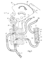
- reference 1 designates the steering wheel of a motor vehicle, this steering wheel being associated with an air distributor 2, hollow, of generally cylindrical shape, formed of a fixed circular ring 3 and a movable ring 4, also circular and nested with rotary sliding on the fixed ring, the latter being in particular linked to a tubular element (not shown) which constitutes the shaft surrounding the steering column by which the wheel 1 transmits its rotational movements to the wheels of the vehicle, this column and its organs of transmission, in themselves conventional in the art and whose detail does not matter to the invention so that it is not necessary to describe here, being simply shown schematically in the drawing by an axis 5, shown under the shape of a dotted line extending in a direction substantially perpendicular to the plane in which the steering wheel 1 is located.
- an air distributor 2 hollow, of generally cylindrical shape, formed of a fixed circular ring 3 and a movable ring 4, also circular and nested with rotary sliding on the fixed ring, the latter being in particular linked to a tubular element (not shown) which constitute
- the movable ring 4 is connected to the flywheel 1 by a connecting piece 6 and freely rotates with it on the fixed ring 3 about the axis 5, sealing means (not shown) being provided between these two rings for isolate the distributor 2 which, in the example in question, substantially matches the shape of a torus, and allow the air it contains does not escape towards the outside of the dispenser, during the relative movement of the crown mobile driven by the steering wheel vis-à-vis the fixed crown.
- the reference 7 designates moreover an air conditioning assembly, able to deliver in the passenger compartment of the vehicle, generally with the aid of an adjustable fan, a main flow of air, which is heated, particularly when it is taken from the vehicle.
- engine cooling system by means of the heat coming from the radiator of the vehicle, being cooled by the frigories produced by a suitable refrigeration system, the temperature of the hot or cold air and the value of the air flow supplied in the passenger compartment being adjustable at the discretion of the user.
- This air conditioning assembly 7 is arranged to take from it an additional air flow by means of a connecting pipe 8, one end of which is connected to this assembly and the other of which opens into the distributor 2, through the fixed ring 3 thereof, this additional air flow being taken through the movable ring 4 by a return tube 9 which conveys it into a hollow zone 10, formed inside the 1 particular steering wheel in the grip circle 11 thereof that the driver squeezes between his hands to impose on the steering column 5 the rotational movements required to drive the vehicle, this hollow zone 10 having a plurality of orifices air outlet 12 provided in the circle 11 and thus arranged in contact or in the immediate vicinity of these hands, to ensure, as appropriate, the heating or cooling depending on the temperature of the air and the setting chosen for the air conditioning package.
- the return tube 9 is connected to an adjustable mixer 13 and a perfume reserve 18, illustrated succinctly on the same Figure 2 but whose Figure 3 to 5 , described below, explain in more detail the embodiment and the implementation, the outputs of the mixer and the perfume reserve being separately joined by communication conduits 17 and 23 to the orifices provided in the hollow zone 10 of the flywheel 1 , arranged to differentiate the flow of air delivered by the outlet orifices 12 distributed in the circle 11 thereof.
- these air outlet orifices 12 are distributed in this zone, as seen in more detail on the Figure 5 , according to two series of orifices 12a and 12b, these orifices, individualized, which are preferably regularly distributed around the periphery of this circle, being arranged in two separate and non-communicating parts 10a and 10b of the hollow zone 10, in order to allow the flow of air, admitted respectively into each of them, by the connecting ducts 17 and 23, to escape independently from the steering wheel .
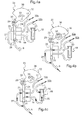
- FIG. 3 illustrates, on a larger scale, a particular embodiment of the adjustable mixer 13 and the room perfume reserve 18 which allows to impregnate at will all or part of the fraction of the additional air flow from the whole 7, conveyed to the steering wheel 1 by the return tube 9.
- the mixer 13, mounted between the distributor 2 and the flywheel 1, comprises a housing 14, provided with an internal housing 15 to which the return tube 9 is connected, this housing, which preferably extends vertically in the housing, being able to itself be placed in communication with the end of two ducts 16 and 17, superimposed according to the height of the housing and respectively joined, at their opposite end, for one at the entrance of the perfume reservoir 18, external to the housing 15, and for the other directly to the portion 10a of the hollow zone 10 of the steering wheel 1.
- This reserve 18 advantageously consists of a refillable capsule 19, in which can be arranged a removable and replaceable cartridge 20 of a room fragrance, impregnating a support 21 enclosed in the cartridge whose outer wall has through holes 22 , the mounting of the cartridge in its capsule being such that the additional air flow leaving the housing 14 of the mixer 13 and conveyed to the reserve 18 by the inlet duct 16 in the direction of the arrows in the drawing, necessarily passes through this cartridge 20 to soak up the perfume of it, before evacuate out of the capsule 19 through the through holes 22, and be taken up by the connecting pipe 23, which is in turn connected to the portion 10b of the hollow zone 10 of the flywheel 1.
- the inner housing 15 of the housing 14 is arranged to cooperate with a slide 24, slidable in this housing and which, in the example shown, has a transverse bore 25 on the one hand, and at its end end a bevelled face 26.
- this transverse bore 25 of the beveled end face 26 on the height of the sliding drawer 24 is determined by construction so that when this face is brought opposite the inlet duct 16 in the reserve perfume 18 and opens more or less, according to its relative position in the housing 14, the communication with this conduit, the bore 25 is shifted upwards relative to the outlet conduit 17, the sliding slide 24 closing in this case any communication by this conduit 17.
- the sliding drawer 24 comprises a tab 28, which extends upwardly to the outside of the housing 14, this tab being provided with an actuating pin 29 projecting, arranged to allow to exert on the drawer a tensile force upward, or conversely downward.
- the pin 29 is freely mounted in an elongate slot 30, provided in an arm 31 of a flat lever 32, pivoting and forming a cam, articulated about an axis 33, eccentric with respect to the pin 29 and carried by a fixed extension 34, secured to the housing 14.
- the part of the lever 32 opposite to the arm 31 which comprises the elongate slot 30 receiving the pin 29, is advantageously shaped in circular sector 35, the center of which coincides with the axis 33, so that a tangential force exerted on this sector can rotate the lever 32 about the axis 33 by allowing the pin 29 to describe the elongated slot 30 of the arm and to exert, as the case, on the sliding drawer 24, a traction or thrust moving in its housing 15 , thus playing on the relative positions of its bore 25 and beveled end face 26 vis-à-vis the inlet and outlet conduits 16 and 17 of the housing 14.
- this sector has on its edge, a striated profile 36, forming a control wheel, on which the finger of the user for the f turn in one direction or the other.
- FIGS. 4a to 4c specify the implementation of the air diffuser according to the invention, according to the wishes of the driver.
- the sliding drawer 24 is in extreme low position, the operating pin 29 being brought into the elongate slot 30 in the position corresponding to a maximum rotation of the circular sector 35 of the pivoting lever 32, controlled by action on the wheel 36, here in the opposite direction of clockwise.
- the slide 24 closes both the inlet duct 16 and the outlet duct 17 of the mixer 13 to the portion 10a of the hollow zone 10 of the flywheel 1, the flow of the additional air supplied by the tube 9 from the distributor 2, being annihilated in its entirety, the outlet orifices 11 of the gripping circle 12 of the steering wheel 1 delivering no flow of air or perfume, to the hands of the driver.
- the additional air flow can thus completely traverse the slide 24 before being taken up in this duct 17 which conveys it to the portion 10a of the hollow zone 10 of the gripping circle 11, from which it is then expelled towards outside and especially to the hands of the driver, through the outlet ports 12a.
- the Figure 4c illustrates an intermediate position where the drilling 25 of the sliding drawer 24 is partially opposite the duct 17, while, simultaneously, the beveled face 26 of the lower end of this drawer is likewise partially disposed in front of the duct 16.
- the mixer 13 makes it possible to authorize, at the same time as the passage through the slide 24 through the bore 25 of a fraction of the additional air flow, admitted from the distributor 2 by the return tube 9 and then collected in the connecting pipe 17 to be conveyed by it in the part 10a of the hollow zone 10 in the circle 11 of the flywheel 1 from which it escapes through the orifices 12a, the other fraction of this flow which passes under the beveled face 26 and beyond in the inlet duct 16 of the perfume reservoir 18, then passing through the cartridge 20 housed in the capsule 19 and charging with the perfume before it is returned to turn in the connecting pipe 23 and subsequently in the portion 10b of the hollow zone 10, from where it escapes to the hands of the driver this time through the orifices 12b.
- the user can thus, by simple pivoting action of the ridged wheel 36 of the circular sector 35 in the appropriate direction, vary and manage as much as desired, the proportions of perfumed or unscented air, brought into the one and the other of the two parts 10a and 10b of the hollow zone 10 of the gripping circle 11 of the flywheel 1 and returned to the outside by the orifices 12a and 12b respectively, in particular between extreme situations where either no passage of air and perfume is not allowed, ie the air is completely impregnated by the perfume, and any intermediate position, where the relative fractions of pure air and perfumed air respectively can be modulated at will, by adjusting the position of the drawer sliding in the inner housing of the housing.
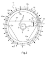
- the Figure 5 illustrates in an external view the steering wheel 1, whose gripping circle 11 has the outlet orifices 12a and 12b for the exhaust of the air, perfumed or not, brought into the steering wheel in a differentiated manner, respectively by the one and by the other of the connecting ducts 17 and 23, as specified above with reference to the diagram of the Figure 2 .
- transverse arm 37 which secures the steering column with the steering wheel 1, and transmits thereto the rotational movements of the gripping circle 11 for the operation of the vehicle.
- an opening 38 has advantageously been provided, through which appears the ribbed profile 36 of the control wheel, allowing the mixer 13 to be adjusted and the fractions of the flow of clean air and perfumed air admitted to be adjusted.
- this wheel is therefore immediately accessible to the driver who can finger easily change the position to act on this flow and adjust the importance of the diffusion of perfume performed.
- the two parts 10a and 10b of the hollow zone 10 formed in the gripping circle 11 of the flywheel 1 are entirely independent of each other, the first 10a, which comprises the orifices 12a, receiving by the duct 17 beyond the passage 25 of the sliding drawer 24 of the adjustable mixer 13, the fraction of the additional air flow directly conveyed through the distributor 2 by the return tube 9, without passing through the perfume reservoir 18.
- the second 10b receives the remaining fraction of the air flow, adjusted according to the position of the slide 24 in its housing 25, this additional flow passing through the conduit 16 to enter the perfume reservoir 18 in proportions at any time adjustable by the wheel 36, before being subsequently delivered to the outside of the steering wheel 1 through the orifices 12b in communication with this portion 10b, separated from the portion 10a.
- This provides an air diffuser with high efficiency and providing the driver, at his hands that hold the steering wheel, increased comfort, both in summer and winter.
Landscapes
- Engineering & Computer Science (AREA)
- Mechanical Engineering (AREA)
- Chemical & Material Sciences (AREA)
- Combustion & Propulsion (AREA)
- Transportation (AREA)
- Power Engineering (AREA)
- Physics & Mathematics (AREA)
- Thermal Sciences (AREA)
- Steering Controls (AREA)
Applications Claiming Priority (1)
| Application Number | Priority Date | Filing Date | Title |
|---|---|---|---|
| FR0759399A FR2924059B1 (fr) | 2007-11-28 | 2007-11-28 | Diffuseur differencie d'air dans habitacle d'un vehicule automobile |
Publications (1)
| Publication Number | Publication Date |
|---|---|
| EP2065290A1 true EP2065290A1 (de) | 2009-06-03 |
Family
ID=39579998
Family Applications (1)
| Application Number | Title | Priority Date | Filing Date |
|---|---|---|---|
| EP08165529A Withdrawn EP2065290A1 (de) | 2007-11-28 | 2008-09-30 | Luftdüse zur Ausströmung eines Luftstromes mittels eines Lenkrades |
Country Status (2)
| Country | Link |
|---|---|
| EP (1) | EP2065290A1 (de) |
| FR (1) | FR2924059B1 (de) |
Cited By (8)
| Publication number | Priority date | Publication date | Assignee | Title |
|---|---|---|---|---|
| CN104943500A (zh) * | 2014-03-31 | 2015-09-30 | 捷温汽车系统(中国)有限公司 | 用于把手、特别是转向机构的加热和冷却装置 |
| WO2015149674A1 (en) * | 2014-03-31 | 2015-10-08 | Gentherm Automotive Systems (China) Ltd. | Heating and cooling device for handles, especially of steering mechanism |
| WO2018115552A1 (es) * | 2016-12-23 | 2018-06-28 | Arco Lopez Miguel Angel | Volante de automóvil con dispositivo difusor de aire |
| US10351158B2 (en) | 2014-03-31 | 2019-07-16 | Gentherm Automotive Systems (China) Ltd. | Heating and cooling device for handles |
| CN112848845A (zh) * | 2021-01-13 | 2021-05-28 | 滁州舜宇模具有限责任公司 | 一种汽车空调出风口用涡旋叶片及其加工工艺 |
| CN113928090A (zh) * | 2021-09-09 | 2022-01-14 | 李其信 | 一种车载可控式防挥发中药香薰装置 |
| IT202200014332A1 (it) | 2022-07-06 | 2024-01-06 | Stephen Carradore | Sistema per il raffrescamento di un volante |
| IT202400004063A1 (it) | 2024-02-26 | 2025-08-26 | Daniele Siciliano | Sistema di conversione energetica a effetto piezoelettrico |
Families Citing this family (1)
| Publication number | Priority date | Publication date | Assignee | Title |
|---|---|---|---|---|
| CN116443092B (zh) * | 2023-01-10 | 2025-07-22 | 深圳曦华科技有限公司 | 车辆方向盘智能加热方法及装置、车辆、存储介质和程序 |
Citations (3)
| Publication number | Priority date | Publication date | Assignee | Title |
|---|---|---|---|---|
| US3149501A (en) * | 1962-01-18 | 1964-09-22 | John A Keir | Air conditioned steering wheel |
| EP0897850A2 (de) * | 1997-08-18 | 1999-02-24 | Daimler-Benz Aktiengesellschaft | Bedienelement in einem Kraftwagen |
| US6533184B1 (en) * | 1999-10-18 | 2003-03-18 | Kiwan Kim | Comfort steering wheel |
-
2007
- 2007-11-28 FR FR0759399A patent/FR2924059B1/fr not_active Expired - Fee Related
-
2008
- 2008-09-30 EP EP08165529A patent/EP2065290A1/de not_active Withdrawn
Patent Citations (3)
| Publication number | Priority date | Publication date | Assignee | Title |
|---|---|---|---|---|
| US3149501A (en) * | 1962-01-18 | 1964-09-22 | John A Keir | Air conditioned steering wheel |
| EP0897850A2 (de) * | 1997-08-18 | 1999-02-24 | Daimler-Benz Aktiengesellschaft | Bedienelement in einem Kraftwagen |
| US6533184B1 (en) * | 1999-10-18 | 2003-03-18 | Kiwan Kim | Comfort steering wheel |
Cited By (11)
| Publication number | Priority date | Publication date | Assignee | Title |
|---|---|---|---|---|
| CN104943500A (zh) * | 2014-03-31 | 2015-09-30 | 捷温汽车系统(中国)有限公司 | 用于把手、特别是转向机构的加热和冷却装置 |
| WO2015149674A1 (en) * | 2014-03-31 | 2015-10-08 | Gentherm Automotive Systems (China) Ltd. | Heating and cooling device for handles, especially of steering mechanism |
| CN104943500B (zh) * | 2014-03-31 | 2019-01-15 | 捷温汽车系统(中国)有限公司 | 用于把手、特别是转向机构的加热和冷却装置 |
| US10351158B2 (en) | 2014-03-31 | 2019-07-16 | Gentherm Automotive Systems (China) Ltd. | Heating and cooling device for handles |
| US10370020B2 (en) | 2014-03-31 | 2019-08-06 | Gentherm Automotive Systems (China) Ltd. | Heating and cooling device for handles, especially of steering mechanism |
| WO2018115552A1 (es) * | 2016-12-23 | 2018-06-28 | Arco Lopez Miguel Angel | Volante de automóvil con dispositivo difusor de aire |
| CN112848845A (zh) * | 2021-01-13 | 2021-05-28 | 滁州舜宇模具有限责任公司 | 一种汽车空调出风口用涡旋叶片及其加工工艺 |
| CN113928090A (zh) * | 2021-09-09 | 2022-01-14 | 李其信 | 一种车载可控式防挥发中药香薰装置 |
| CN113928090B (zh) * | 2021-09-09 | 2024-01-19 | 深圳市宝安区中医院 | 一种车载可控式防挥发中药香薰装置 |
| IT202200014332A1 (it) | 2022-07-06 | 2024-01-06 | Stephen Carradore | Sistema per il raffrescamento di un volante |
| IT202400004063A1 (it) | 2024-02-26 | 2025-08-26 | Daniele Siciliano | Sistema di conversione energetica a effetto piezoelettrico |
Also Published As
| Publication number | Publication date |
|---|---|
| FR2924059A1 (fr) | 2009-05-29 |
| FR2924059B1 (fr) | 2009-12-25 |
Similar Documents
| Publication | Publication Date | Title |
|---|---|---|
| EP2065234B1 (de) | Luftverteiler für Innenraum eines Kraftfahrzeugs | |
| EP2065290A1 (de) | Luftdüse zur Ausströmung eines Luftstromes mittels eines Lenkrades | |
| EP1339299B1 (de) | Haartrockner mit einer vorrichtung zum verändern der auslassquerschnitt des luftstromes | |
| EP1404995A1 (de) | Steuerventil für kühlkreislauf | |
| FR2531666A1 (fr) | Installation de climatisation pour un vehicule automobile, notamment pour une voiture de tourisme | |
| EP1242259A1 (de) | Heizungs- und klimaanlage für fahrzeuge | |
| EP2769862A1 (de) | Perfümzerstäubungsgerät in dem Innenraum eines Fahrzeugs, wie ein Kraftfahrzeug | |
| FR2924058A1 (fr) | Diffuseur d'air pour habitacle de vehicule automobile | |
| WO2020109685A1 (fr) | Aerateur mince a effet coanda pour vehicule automobile | |
| FR2720693A1 (fr) | Dispositif de chauffage et/ou d'aération de l'habitacle d'un véhicule. | |
| EP0125976B1 (de) | Klappensystem für Luftstromverteilung einer Klimaanlage für Kraftfahrzeuge | |
| EP1838541B1 (de) | Luftdüse für ein kraftfahrzeug zur montage am ausgang eines in den insassenraum des fahrzeuges führenden entlüftungsrohres und entsprechendes fahrzeug | |
| WO2015091715A1 (fr) | Organe d'aeration de vehicule automobile et dispositif d'aeration comprenant un tel organe | |
| FR3083164A1 (fr) | Aerateur a effet coanda pour vehicule automobile | |
| FR2605942A1 (fr) | Dispositif pour la commande coordonnee de deux organes de reglage de debit de fluides | |
| FR2720981A1 (fr) | Boîtier de chauffage et de distribution d'air pour véhicules automobiles. | |
| EP0246948A1 (de) | Heiz- und Belüftungseinrichtung für ein Kraftfahrzeug | |
| WO2002032703A1 (fr) | Appareils de chauffage, de ventilation et/ou de climatisation | |
| EP1702149B1 (de) | Verfahren zur temperaturregelung eines fluidstromkreises, insbesondere für einen motorkühlkreislauf | |
| FR2809349A1 (fr) | Barillet d'aerateur pour vehicule automobile | |
| WO1999033677A2 (fr) | Dispositif de chauffage-climatisation integre dans une planche de bord de vehicule automobile | |
| EP1697668B1 (de) | Wärmeregelventil für ein fluidstromsystem, insbesondere für ein motorkühlsysteme | |
| FR2833532A1 (fr) | Dispositif pour l'odorisation de l'habitacle d'un vehicule automobile | |
| EP1366935B1 (de) | Vorrichtung zur Erzeugung einer temperaturgeregelten Luftströmung und Gerät mit einer solchen Vorrichtung | |
| FR2861652A1 (fr) | Dispositif de l'orientation des ailettes ou volets deflecteurs d'air d'un vehicule automobile |
Legal Events
| Date | Code | Title | Description |
|---|---|---|---|
| PUAI | Public reference made under article 153(3) epc to a published international application that has entered the european phase |
Free format text: ORIGINAL CODE: 0009012 |
|
| AK | Designated contracting states |
Kind code of ref document: A1 Designated state(s): AT BE BG CH CY CZ DE DK EE ES FI FR GB GR HR HU IE IS IT LI LT LU LV MC MT NL NO PL PT RO SE SI SK TR |
|
| AX | Request for extension of the european patent |
Extension state: AL BA MK RS |
|
| AKX | Designation fees paid | ||
| REG | Reference to a national code |
Ref country code: DE Ref legal event code: 8566 |
|
| STAA | Information on the status of an ep patent application or granted ep patent |
Free format text: STATUS: THE APPLICATION IS DEEMED TO BE WITHDRAWN |
|
| 18D | Application deemed to be withdrawn |
Effective date: 20091204 |