EP2065597A1 - Drucktauscher mit gespaltener kammer - Google Patents
Drucktauscher mit gespaltener kammer Download PDFInfo
- Publication number
- EP2065597A1 EP2065597A1 EP07788594A EP07788594A EP2065597A1 EP 2065597 A1 EP2065597 A1 EP 2065597A1 EP 07788594 A EP07788594 A EP 07788594A EP 07788594 A EP07788594 A EP 07788594A EP 2065597 A1 EP2065597 A1 EP 2065597A1
- Authority
- EP
- European Patent Office
- Prior art keywords
- fluid
- pressure
- pressurized
- chambers
- scpe
- Prior art date
- Legal status (The legal status is an assumption and is not a legal conclusion. Google has not performed a legal analysis and makes no representation as to the accuracy of the status listed.)
- Withdrawn
Links
Images





Classifications
-
- F—MECHANICAL ENGINEERING; LIGHTING; HEATING; WEAPONS; BLASTING
- F04—POSITIVE - DISPLACEMENT MACHINES FOR LIQUIDS; PUMPS FOR LIQUIDS OR ELASTIC FLUIDS
- F04F—PUMPING OF FLUID BY DIRECT CONTACT OF ANOTHER FLUID OR BY USING INERTIA OF FLUID TO BE PUMPED; SIPHONS
- F04F13/00—Pressure exchangers
-
- F—MECHANICAL ENGINEERING; LIGHTING; HEATING; WEAPONS; BLASTING
- F04—POSITIVE - DISPLACEMENT MACHINES FOR LIQUIDS; PUMPS FOR LIQUIDS OR ELASTIC FLUIDS
- F04B—POSITIVE-DISPLACEMENT MACHINES FOR LIQUIDS; PUMPS
- F04B9/00—Piston machines or pumps characterised by the driving or driven means to or from their working members
- F04B9/08—Piston machines or pumps characterised by the driving or driven means to or from their working members the means being fluid
- F04B9/10—Piston machines or pumps characterised by the driving or driven means to or from their working members the means being fluid the fluid being liquid
- F04B9/109—Piston machines or pumps characterised by the driving or driven means to or from their working members the means being fluid the fluid being liquid having plural pumping chambers
- F04B9/117—Piston machines or pumps characterised by the driving or driven means to or from their working members the means being fluid the fluid being liquid having plural pumping chambers the pumping members not being mechanically connected to each other
- F04B9/1176—Piston machines or pumps characterised by the driving or driven means to or from their working members the means being fluid the fluid being liquid having plural pumping chambers the pumping members not being mechanically connected to each other the movement of each piston in one direction being obtained by a single-acting piston liquid motor
Definitions
- the invention is comprised within the field of pressure exchangers, which are for transmitting dynamic pressure from one fluid to another different fluid.
- the invention is transformed into a new pumping system for any type of fluids, and even into a new electric power generation system.
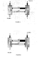
- Pressure exchangers were invented over more than twenty-five years ago and they basically consist of pressurizing one fluid (fluid 1 in Figure 1 ) from the pressure of another fluid, which is depressurized after the process (fluid 2).
- the fluid 1 is introduced in the interconnecting chambers by means of a system of shut-off and check valves, represented by the gray boxes. Once filled, the fluid 2 is allowed to pass through the other end, displacing said fluid by pushing an transmitting intermediate member which transmits the residual pressure between them, separating them (usually a disc or piston, though occasionally an intermediate fluid or any other system is used). The fluid 1 is thus pressurized. Then the inlet of the fluid 2 is shut off and a discharge valve opens. The fluid 1 is again allowed to pass through by means of the valve system, displacing fluid 2 (which now does not have pressure), discharging it through the drain.
- the system is assembled with two parallel interconnecting lines and is electronically controlled such that at all times the disc or piston of each tube is located in the opposite position with regard to the center (reverse line operation) to thus achieve the most constant pressure possible at the outlet of the fluid 1, and to likewise achieve the greatest possible exploitation of the pressure of the fluid 2.
- Figure 1 shows the fluids 1 and 2 using lighter shades when they do not have pressure and darker shades when they are pressurized. These different shades will be maintained throughout all the figures attached to this description.
- Pressure exchangers have traditionally been used in mining to displace residual processing water with clean water and the system is used without discs or pistons since it does not matter if both fluids mix.
- SCPEs Split-chamber pressure exchangers
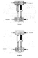
- pressure exchangers characterized in that the pressure exchange chambers are split in two, one for each of the fluids, as shown in Figure 3 . Each of the fluids therefore only passes through the corresponding chamber thereof, such that said fluids cannot be mixed (and the second problem described in the preceding section is therefore solved).
- Drains can be arranged at the opposite ends of the chambers in case it is necessary to drain a small amount of the fluids which may be lost through the disc or piston seals.
- a first possible arrangement would be the one shown in Figure 3 , in which the cross sections of each chamber are identical. The same pressure would thus be transmitted from the pressurized fluid to the fluid to be pressurized, except obviously mechanical losses.
- the inventive system allows another arrangement, in which the cross sections of the chambers are different ( Figure 4 ), and therefore the transmitted pressure is also different (the pressure ratio will be equal to the area ratio, except obviously for mechanical losses, since the net force is the same).
- the problem of the need for the booster pump mentioned above in the description of the technical problem involved can thus obviously be solved.
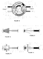
- auxiliary U-shaped tube which interconnects both lines as shown in Figure 6 , and it is a telescopic tube on both sides of the "U", being rigidly supported by the base of the "U".
- the ends of the "U” are attached to the discs or pistons of their respective lines, and the "U” is filled with an incompressible fluid. Therefore, when the fluid 2 under pressure enters its chamber, not only does it apply pressure to its disc or piston to displace fluid 1, but it also transmits part of its energy to the disc or piston of the other line to aid fluid 1 of the other line in displacing the depressurized fluid 2 in said line and in overcoming the friction of the discs or pistons and their weight and that of the depressurized fluid 2 if necessary.
- the cross section of the tube must be such that the energy transferred to the disc or piston of the other line is the necessary minimum.
- the reverse line operation is furthermore assured by means of this system, thus simplifying the system control electronics. It can be assembled in any type of pressure exchangers, whether they are split chambers or not. Obviously, instead of being a telescopic tube they could be several telescopic tubes equidistant from one another and from the center, or a ring made up of several sections of the same length and equidistant for the purpose of better distributing the stress on the discs or pistons.
- curved or circular chamber lines can also be arranged, in which case the attachment between the discs or pistons will be curved and have the same radius, and will be attached to the center by means of a ball-type joint ( Figure 7 ).
- An increase of the pressure transmitted can thus be achieved depending on the distance of the chambers of both fluids to the center, without needing to change the cross section of the chambers, though without jeopardizing the possibility of being able to combine both effects.
- the splitting of chambers can be applied to all types of traditional pressure exchangers developed today.
- traditional pressure exchangers which are mentioned perhaps because they are the most distinguished of all of them, which are based on the same operating principle but consisting of a cylinder with a series of inner conduits through which the fluids pass, the pressures being exchanged. They further have the particularity that the actual cylinder rotates about its own axis.
- the chambers of this type of exchanger can also be split to obtain the advantages herein explained.
- SCPEs in which in order to transmit pressures the chambers are telescopic and push one another, rather than the rigidly attached double disc or piston system.
- Figure 8 shows a schematic depiction thereof. SCPEs with bellows-type chambers
- SCPEs in which in order to transmit pressures the chambers are bellows-type chambers and push one another, rather than the rigidly attached double disc or piston system.
- Figure 9 shows a schematic depiction thereof.
- SCPEs which are SCPEs in which the chambers in each line are arranged such that those corresponding to the fluid to be pressurized have rigid walls, and those of the fluid which yields its pressure are membrane-type chambers, the latter being included within the rigid wall type.
- Figure 10 shows a schematic depiction thereof.
- any of the possible arrangements can be combined such that the chambers corresponding to one of the fluids can have one arrangement and the chamber corresponding to the other fluid can have a different arrangement.
- Figures 11 Two of the possible combinations are depicted in Figures 11 (piston-type chambers/telescopic chambers) and 12 (telescopic chambers/bellows-type chambers).
- Multistage SCPEs consist of the splitting the chambers of the fluid the pressure of which is yielded into several chambers, which may or may not be used depending on the available pressure of the fluid, by means of a valve system, thus being able to transmit the most homogenous pressure possible to the fluid to be pressurized, as shown in Figure 13 .
- the chambers which are split are the chamber of the fluid to be pressurized, thus pressurizing it at different pressures depending on the needs at all times.
- all the chambers can be filled continuously so as to allow opening auxiliary chambers midway through if the feed pressure changes, maximally exploiting the energy of the pressurized fluid, as shown in Figure 14 .
- FIGS. 13 and 14 depict multistage SCPEs with piston-type chambers, but they can obviously also be provided with telescopic, bellows-type, membrane-type or mixed chambers. They are further depicted with the different chambers by way of concentric and overlapping cylinders, but they can obviously be arranged with any possible geometry provided that the pressurized fluid pushes through all the chambers in the same direction.
- Figure 15 depicts a multistage SCPE with a circular arrangement, which allows the aided reverse operation, as explained above.
- the control system can adjust the stages that must start operating also depending on these pressures.
- VSCPEs Variable section SCPEs
- SCPEs design of SCPEs rests on their being able to have a variable section in any of the fluid chambers thereof fluid (one, several or all). To that end, it is essential for the piston, the actual chambers, or both, to be able to have variable sections. Both possibilities are described below.
- pistons which have a section that changes along the piston stroke. To that end, the chamber on which they are housed must have a variable cross section.
- the pistons must be designed such that their section can increase or decrease, maintaining their own rigidity and the seal of their attachments with the walls of the corresponding chamber thereof.
- any type of mechanical or pneumatic system, or a combination thereof, can be used.
- Figures 16 and 17 depict the starts and the ends of the stroke of a variable section piston.
- a piston-type exchanger with a single line has been considered.
- Variable geometry chambers either telescopic or piston-type chambers, can be used in these cases, which can open or close and even open at one end and close at the other.
- Figures 18 and 19 depict a single-line piston-type VSSCPE with one of its chambers being a variable section chamber.
- auxiliary telescopic cylinders which are filled with an incompressible fluid and fixed at one end to the wall of the chamber and at the other end to a fixed wall, as shown in Figures 18 and 19 , may be particularly interesting.
- the walls of the chamber are moved by extracting fluid from or introducing fluid into the cylinders according to the needs of the system.
- Telescopic cylinders could obviously be replaced with a fixed chamber filled with an auxiliary fluid on which the actual wall of the chamber of the VSSCPE would move like a piston ( Figures 20 and 21 ).
- FIG. 26 depicts a possible design for this purpose, which consists of providing the chamber with one of the fluids of an initial variable section span, during which the piston accelerates until reaching the design speed, at which time the straight span is reached, and the speed is kept constant since the system is designed so that at that time the force exerted on the piston by the fluid the pressure of which is yielded is equal to the force exerted by the fluid to be pressurized thereon plus losses due to friction corresponding to the design speed.
- the chamber has a section step, and again it is designed to reach the desired speed of the piston in the initial span with a larger section.
- the piston would have the possibility of being separated into two or more parts, such that during the first span it is kept rigidly attached and during the second span it separates. This could be done with any type of mechanical system.
- SCPEs having any of the presented arrangements can be arranged in series ( Figure 29 ), or in parallel ( Figure 30 ).
- mixed systems with pumps can be arranged to increase the pressure of the pressurized fluid and/or the pressure of the fluid to be pressurized at the inlet and/or at the outlet of the pressure exchanger ( Figure 31 ), without jeopardizing the fact that they can also be arranged in series or in parallel.
- a card with a processor can be assembled in situ, or signals can be sent to a central computer controlling them.
- the control system will be more complex as it must regulate the valves depending on the inlet and/or outlet pressures of the two fluids involved.
- the lines of the chambers in any of the longitudinal arrangements they can be straight, curved and even circular, and the cross section thereof may be circular, elliptical, triangular, square, rectangular, polygonal or any imaginable cross section.
- the energy transfer performance is thus optimized since it is not used for an unnecessary acceleration of the double or single disc or piston.
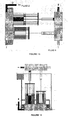
- Figures 36 to 39 diagrammatically depict the operating process of a multistage SCPE, with seven concentric chambers located on the side of the pressurized feed fluid.
- Figure 36 shows the first of the lines starting to be filled and the second one starting to drain.
- the pressure gage at the inlet of the pressurized fluid records a high pressure of the fluid, therefore the valve feeding the concentric chambers closes and therefore only pressurized fluid enters the central cylinder.
- the valve system in the gray box in the figure allows the passage of pressurized fluid to the first line and prevents the passage thereof to the second line. Likewise, said system allows draining said already depressurized fluid from the second line.
- the valve feeding the concentric chambers in the valve system shown in the figure in the second line is closed, it allows draining the fluid from the central cylinder but not from the remaining cylinders. The fluid contained in the remaining cylinders therefore exits through the conduit leading it to the auxiliary tank.
- the system therefore works by raising the fluid of the first line and lowering the fluid of the second line.
- the auxiliary tank furthermore feeds the concentric cylinders of the first line, since the valves giving access to each of them open.
- the level in the auxiliary tank does not drop, since it is in turn fed by the depressurized fluid of the concentric cylinders of the second line. For this reason such tank could even be eliminated and converted into a flow-off.
- the lines work up to a mid point as depicted in Figure 37 .
- the pressure gage detects a drop in the pressure of the pressurized feed fluid, and for this reason the control system immediately calculates how many chambers must start working in order to keep the pressure transmitted to the fluid to be pressurized as constant as possible depending on said drop.
- the control system would activate four of the concentric cylinders, as shown in Figure 38 . Obviously, since the concentric cylinders are filled with fluid depressurized coming from the auxiliary tank, these cylinders are automatically pressurized with the single opening and closing of the corresponding valves, the fluid therefore not losing energy while it fills the concentric cylinders if they are empty.
Landscapes
- Engineering & Computer Science (AREA)
- Mechanical Engineering (AREA)
- General Engineering & Computer Science (AREA)
- Separation Using Semi-Permeable Membranes (AREA)
- Other Liquid Machine Or Engine Such As Wave Power Use (AREA)
Applications Claiming Priority (3)
| Application Number | Priority Date | Filing Date | Title |
|---|---|---|---|
| ES200601694A ES2321997B1 (es) | 2006-06-13 | 2006-06-13 | Intercambiadores de presion de camaras desdobladas. |
| ES200602232A ES2321999B1 (es) | 2006-06-13 | 2006-08-17 | Intercambiadores de presion de camaras desdobladas multietapa. |
| PCT/ES2007/000346 WO2007147914A1 (es) | 2006-06-13 | 2007-06-11 | Intercambiadores de presión de cámaras desdobladas (ipcd's) |
Publications (1)
| Publication Number | Publication Date |
|---|---|
| EP2065597A1 true EP2065597A1 (de) | 2009-06-03 |
Family
ID=38833100
Family Applications (1)
| Application Number | Title | Priority Date | Filing Date |
|---|---|---|---|
| EP07788594A Withdrawn EP2065597A1 (de) | 2006-06-13 | 2007-06-11 | Drucktauscher mit gespaltener kammer |
Country Status (3)
| Country | Link |
|---|---|
| EP (1) | EP2065597A1 (de) |
| AU (1) | AU2007262970A1 (de) |
| WO (1) | WO2007147914A1 (de) |
Cited By (5)
| Publication number | Priority date | Publication date | Assignee | Title |
|---|---|---|---|---|
| DE102009020932A1 (de) * | 2009-05-12 | 2010-11-18 | Fraunhofer-Gesellschaft zur Förderung der angewandten Forschung e.V. | Druckaustauscher mit Linearantrieb |
| EP2483207A4 (de) * | 2009-09-30 | 2014-09-03 | Beijing China Water Golden Water Desalination Technology Applic And Res Co Ltd | Flüssigkeitsbehandlungssystem |
| WO2015104660A1 (en) * | 2014-01-08 | 2015-07-16 | Hofmeyr Robert Mark | A gravitationally assisted liquid pump assembly |
| WO2016033508A1 (en) * | 2014-08-29 | 2016-03-03 | Energy Recovery, Inc. | Systems and method for pump protection with a hydraulic energy transfer system |
| WO2017144748A1 (es) * | 2016-02-25 | 2017-08-31 | Universidad A Distancia De Madrid Udima, S.A. | Sistema de bombeo hidráulico a alta presión sin consumo energético externo y procedimiento para la puesta en práctica del mismo |
Families Citing this family (1)
| Publication number | Priority date | Publication date | Assignee | Title |
|---|---|---|---|---|
| SG165201A1 (en) * | 2009-03-23 | 2010-10-28 | Vaz Guy Andrew | Power generation |
Family Cites Families (8)
| Publication number | Priority date | Publication date | Assignee | Title |
|---|---|---|---|---|
| US776106A (en) * | 1901-12-23 | 1904-11-29 | Alexis Beurrier | Apparatus for raising fluids by solar heat. |
| US2490118A (en) * | 1945-07-23 | 1949-12-06 | Hygroequipments Ltd | Pump |
| US2807215A (en) * | 1955-07-28 | 1957-09-24 | Crane Packing Co | Variable displacement pump |
| DE1294812B (de) * | 1961-02-21 | 1969-05-08 | Conen | Foerdermengenverstellbare Druckmittelpumpe |
| US3885393A (en) * | 1973-09-07 | 1975-05-27 | Us Energy | Hydraulic load matching device |
| US5062268A (en) * | 1990-02-02 | 1991-11-05 | The University Of British Columbia | Fluid actuator |
| JP2003013904A (ja) * | 2001-06-27 | 2003-01-15 | Karasawa Fine Ltd | 増圧装置 |
| GB2403986B (en) * | 2003-07-15 | 2007-09-05 | Paul Kristian Hatchwell | Natural energy system for power generation and storage |
-
2007
- 2007-06-11 WO PCT/ES2007/000346 patent/WO2007147914A1/es not_active Ceased
- 2007-06-11 EP EP07788594A patent/EP2065597A1/de not_active Withdrawn
- 2007-06-11 AU AU2007262970A patent/AU2007262970A1/en not_active Abandoned
Non-Patent Citations (1)
| Title |
|---|
| See references of WO2007147914A1 * |
Cited By (5)
| Publication number | Priority date | Publication date | Assignee | Title |
|---|---|---|---|---|
| DE102009020932A1 (de) * | 2009-05-12 | 2010-11-18 | Fraunhofer-Gesellschaft zur Förderung der angewandten Forschung e.V. | Druckaustauscher mit Linearantrieb |
| EP2483207A4 (de) * | 2009-09-30 | 2014-09-03 | Beijing China Water Golden Water Desalination Technology Applic And Res Co Ltd | Flüssigkeitsbehandlungssystem |
| WO2015104660A1 (en) * | 2014-01-08 | 2015-07-16 | Hofmeyr Robert Mark | A gravitationally assisted liquid pump assembly |
| WO2016033508A1 (en) * | 2014-08-29 | 2016-03-03 | Energy Recovery, Inc. | Systems and method for pump protection with a hydraulic energy transfer system |
| WO2017144748A1 (es) * | 2016-02-25 | 2017-08-31 | Universidad A Distancia De Madrid Udima, S.A. | Sistema de bombeo hidráulico a alta presión sin consumo energético externo y procedimiento para la puesta en práctica del mismo |
Also Published As
| Publication number | Publication date |
|---|---|
| WO2007147914B1 (es) | 2008-02-07 |
| WO2007147914A1 (es) | 2007-12-27 |
| AU2007262970A1 (en) | 2007-12-27 |
Similar Documents
| Publication | Publication Date | Title |
|---|---|---|
| US20100014997A1 (en) | Split-chamber pressure exchangers | |
| DK176721B1 (da) | Fremgangsmode til akkumulering og udnyttelse af vedvarende energi | |
| EP2065597A1 (de) | Drucktauscher mit gespaltener kammer | |
| EP2035691B1 (de) | Vorrichtung und verfahren zur regelung des energiepotentials einer in einer rohrleitung angeordneten flüssigkeitssäule | |
| FI113685B (fi) | Tuotantolaitteisto | |
| CN101952583B (zh) | 用于脱盐及电力的海浪能量 | |
| CA2757255C (en) | Tide activated device to operate a turbine generator | |
| US7713032B2 (en) | High pressure tide actuated fluid pump | |
| EP2358992A1 (de) | Kraftwerk, verfahren zur erzeugung von energie und anwendung des kraftwerks | |
| WO2011150354A2 (en) | Wave energy transfer system | |
| US20080025852A1 (en) | Economical tide/wave/swell/wind/solar powered high pressure fluid pump | |
| IL274332B1 (en) | Effective Wave Power Plant for Production of Clean Electricity or Clean Water from the Waves or a Combined System | |
| CN107120226A (zh) | 一种波浪能俘获装置 | |
| US12078140B2 (en) | Method of electric energy generation and power generation system, in particular a power plant | |
| Geng et al. | Development and fluid fluctuation analysis of a novel valve-controlled energy recovery device for small-scale reverse osmosis desalination systems | |
| CN103112927A (zh) | 以压缩空气为动力的变送系统、海水淡化处理方法与系统 | |
| EP1562693B1 (de) | Entsalzungsvorrichtung | |
| WO2016091238A1 (de) | Vorrichtung zur regenerativen stromerzeugung mittels auftriebskräften | |
| Geisler et al. | Optimization of the energy demand of reverse osmosis with a pressure-exchange system | |
| EP3421817B1 (de) | Hydraulisches hochdruckpumpensystem ohne erforderliche externe stromversorgung zum betrieb davon | |
| CA2783957A1 (en) | Energy generating apparatus and method | |
| EP4532922B1 (de) | Wellenenergiewandler | |
| WO2025012692A1 (en) | Wave energy converter | |
| CA2970368C (en) | Apparatuses for the functioning of a floating methanization system | |
| DE102018008256A1 (de) | Pegel-Turbine |
Legal Events
| Date | Code | Title | Description |
|---|---|---|---|
| PUAI | Public reference made under article 153(3) epc to a published international application that has entered the european phase |
Free format text: ORIGINAL CODE: 0009012 |
|
| 17P | Request for examination filed |
Effective date: 20090115 |
|
| AK | Designated contracting states |
Kind code of ref document: A1 Designated state(s): AT BE BG CH CY CZ DE DK EE ES FI FR GB GR HU IE IS IT LI LT LU LV MC MT NL PL PT RO SE SI SK TR |
|
| AX | Request for extension of the european patent |
Extension state: AL BA HR MK RS |
|
| STAA | Information on the status of an ep patent application or granted ep patent |
Free format text: STATUS: THE APPLICATION IS DEEMED TO BE WITHDRAWN |
|
| 18D | Application deemed to be withdrawn |
Effective date: 20120103 |
|
| DAX | Request for extension of the european patent (deleted) |