EP2065697B1 - Système de mesure de gaz - Google Patents
Système de mesure de gaz Download PDFInfo
- Publication number
- EP2065697B1 EP2065697B1 EP08167482A EP08167482A EP2065697B1 EP 2065697 B1 EP2065697 B1 EP 2065697B1 EP 08167482 A EP08167482 A EP 08167482A EP 08167482 A EP08167482 A EP 08167482A EP 2065697 B1 EP2065697 B1 EP 2065697B1
- Authority
- EP
- European Patent Office
- Prior art keywords
- peak
- signal
- intensity
- gas
- measurement signal
- Prior art date
- Legal status (The legal status is an assumption and is not a legal conclusion. Google has not performed a legal analysis and makes no representation as to the accuracy of the status listed.)
- Active
Links
Images




Classifications
-
- G—PHYSICS
- G01—MEASURING; TESTING
- G01N—INVESTIGATING OR ANALYSING MATERIALS BY DETERMINING THEIR CHEMICAL OR PHYSICAL PROPERTIES
- G01N21/00—Investigating or analysing materials by the use of optical means, i.e. using sub-millimetre waves, infrared, visible or ultraviolet light
- G01N21/17—Systems in which incident light is modified in accordance with the properties of the material investigated
- G01N21/25—Colour; Spectral properties, i.e. comparison of effect of material on the light at two or more different wavelengths or wavelength bands
- G01N21/31—Investigating relative effect of material at wavelengths characteristic of specific elements or molecules, e.g. atomic absorption spectrometry
- G01N21/35—Investigating relative effect of material at wavelengths characteristic of specific elements or molecules, e.g. atomic absorption spectrometry using infrared light
- G01N21/3504—Investigating relative effect of material at wavelengths characteristic of specific elements or molecules, e.g. atomic absorption spectrometry using infrared light for analysing gases, e.g. multi-gas analysis
-
- G—PHYSICS
- G01—MEASURING; TESTING
- G01N—INVESTIGATING OR ANALYSING MATERIALS BY DETERMINING THEIR CHEMICAL OR PHYSICAL PROPERTIES
- G01N21/00—Investigating or analysing materials by the use of optical means, i.e. using sub-millimetre waves, infrared, visible or ultraviolet light
- G01N21/17—Systems in which incident light is modified in accordance with the properties of the material investigated
- G01N21/25—Colour; Spectral properties, i.e. comparison of effect of material on the light at two or more different wavelengths or wavelength bands
- G01N21/31—Investigating relative effect of material at wavelengths characteristic of specific elements or molecules, e.g. atomic absorption spectrometry
- G01N21/314—Investigating relative effect of material at wavelengths characteristic of specific elements or molecules, e.g. atomic absorption spectrometry with comparison of measurements at specific and non-specific wavelengths
- G01N2021/317—Special constructive features
- G01N2021/3174—Filter wheel
Definitions
- the present invention generally relates to the field of gas analysis and in particular to a gas analyzing system and a method for the analysis of respiratory gases supplied to and received from a mammal, for example, a patient undergoing general anaesthesia.
- Gas analysis and the measurement of a gas concentration with infrared technology is generally implemented by means of a non-dispersive method, i.e. by measuring absorption through an appropriately selected optical bandpass filter.
- the measured attenuated radiation transmitted through the gas layer will be an integrated value of transmissions existing over various wavelengths of this band.
- Main stream analysers can be made less expensive, more energy-lean and more responsive than side stream analysers, since the need for sample flow handling (pumps, hoses, etc.) is obviated. Consequently, main stream gas analysers are preferred over side stream analysers.
- the light from an IR-emitter passes through the gas mixture of a measuring chamber and is filtered by a narrow-band optical bandpass filter.
- the gases absorb infrared light at gas specific wavelengths and during the passage through the gas mixture, the gases in the mixture hence absorb some of the light.
- the partly absorbed light is detected by an IR-detector and the intensity of the detected light is determined.
- the intensity i.e. the intensity corresponding to the light that not was absorbed by the gas or the gases, a measure of the concentration of a gas or gases in the gas mixture can be obtained.
- a gas analyzer for determining the identity of a specific gas of a number of gases having overlapping absorption spectra and the concentration thereof is disclosed.
- a DC infrared source generates an optical beam that passes through a chamber containing a gas sample and the strikes a filter wheel having three filters for three different gases and one reference filter. The filter wheel is rotated by a stepped motor.
- an object of the present invention is to provide a small, compact and light gas analyser for multigas analysis.
- a further object of the present invention is to provide a gas analyzer having a high degree of accuracy and reliability at multigas analysis in respiratory care.
- Yet another object of the present invention is to provide a gas analyzer that easily can be adapted for use both in main stream and side stream configurations.
- a gas analyzing system for the analysis of respiratory gases to and from a mammal.
- the gas analyzing system comprising a light transmitter which includes an IR-emitter adapted to emit at least one measuring beam, which light transmitter being arranged to emit the measuring beam into a gas mixture including the respiratory gases, a filter component including a number of filters having different transmission wavelength ranges, the filter component being arranged to position the filters such that the at least one measuring beam passes through the number of filters one at a time, a light receiver including an IR-detector adapted to receive the measurement beam and to generate at least one measurement signal reflecting an optical energy of the measurement beam, and a signal processing circuitry adapted to receive the at least one measurement signal.
- the signal processing circuitry comprises a peak detector adapted to identify peaks in the at least one measurement signal, each peak corresponding to a filter of the filter component, and an intensity measure estimating unit adapted to determine an intensity measure of each identified peak using at least one predetermined estimation function.
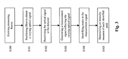
- a method for analyzing respiratory gases supplied to and received from a mammal comprises the steps of emitting at least one measuring beam into a gas mixture including the respiratory gases, positioning a filter component including a number of filters having different transmission wavelength ranges such that the at least one measuring beam passes through the number of filters one at a time, receiving the measurement beam and generating at least one measurement signal reflecting an optical energy of the measurement beam, identifying peaks in the at least one measurement signal, each peak corresponding to a filter of the filter component, determine an intensity measure of each identified peak using at least one predetermined estimation function describing at least a part of the measurement signal.
- the detector signal will not decrease to its reference level during the "dark" periods, i.e. during periods between two consecutive filters of the filter wheel when the incident light impinges on the filter wheel part between the consecutive filters. Consequently, there is a problem in determining the intensity of the peaks of the signal, i.e. when a filter passes through the beam of emitted light.
- the filter component is designed to obtain such "dark periods", i.e.
- the filter component is designed with small filter apertures and respective spacing between consecutive filters being large enough to allow the detector to detect the reference level or null level of the intensity between two consecutive filters.
- the physical restrictions put on the filter component for example, with regard to size, number of filters, weight, etc. do not allow such traditional design.
- the invention is therefore based on idea of instead using the measured signal during the light periods, i.e. during the periods when the emitted light impinges on the optical filters and to estimate an intensity of the peaks in the signal, i.e. the parts of the signal corresponding to a filter.
- the filter wheel can be made small and compact at the same time as it can include several filters allowing for multigas analysis. That is, it is not necessary to measure the actual reference or null intensity for each peak as in the prior art.
- a further advantage is that the distance or respective spacing between consecutive filter apertures or openings can be made smaller and hence the apertures can be made larger and, therefore, the signal to noise ratio can be improved, which, in turn, provides for an improved accuracy and reliability of the measurements.
- the peak detector further comprises a time alignment circuit adapted to perform a time alignment between identified peaks and the at least one predetermined estimation function.
- the predetermined estimation function is a function describing at least a part of the measurement signal.
- the peak detector is adapted to determine peak characterizing measures of the measurement signal and to use the peak characterizing measure to identify the peaks.
- the peak characterizing measure may, for example, be the maximum derivative, the maximum amplitude, or a zero crossing in a difference signal of a delayed signal and the measurement signal.
- the peak detector comprises a delay buffer adapted to receive the measurement signal and to delay the signal a predetermined period, a combiner adapted to combine the delayed signal with the measurement signal to create a difference signal, and a zero crossing identifier adapted to identify zero crossing in the difference signal and to deliver a peak detection indication based on the identified zero crossing.
- the predetermined delay period corresponds to about the width of the identified peak.
- the peak detector further comprises a qualify and small peak detection logic adapted to qualify peaks using a threshold, which may have a predetermined threshold or which may be adaptive. Peaks having a magnitude being above the threshold are qualified as being a peak. Further, the qualify and small peak detection logic is adapted to detect small peaks using a predetermined inter-peak distance.
- the gas analyzing system comprises an intensity measure estimating unit including a delay buffer adapted to receive the measurement signal, to delay the signal a period, which delay may be predetermined or which may be adaptive, to receive the peak detection indication from the peak detector, and to create a time aligned peak using the delayed measurement signal and the peak detection indication, a model function circuit adapted to receive the peak detection indication from the peak detector and to select the at least one predetermined estimation function, which may be a function describing at least a part of the measurement signal on basis of the peak detection indication; and an intensity estimator adapted to receive the predetermined estimation function and the time aligned peak and to estimate an intensity of each peak using the predetermined estimation function and the time aligned peak.
- an intensity measure estimating unit including a delay buffer adapted to receive the measurement signal, to delay the signal a period, which delay may be predetermined or which may be adaptive, to receive the peak detection indication from the peak detector, and to create a time aligned peak using the delayed measurement signal and the peak detection indication, a model function circuit adapted
- the gas analyzing system comprises an intensity measure estimating unit comprising an inverse filter adapted to inverse filtering the measurement signal, and an intensity estimator adapted to: estimate a base line using interpolation between reference levels in the filtered signal; subtract the estimated base line from the filtered signal to create a base line corrected signal; and calculate the intensity for each peak using values of the base line corrected signal.
- the gas analyzing system comprises an intensity measure estimating unit including intensity estimator adapted to: calculate the intensity for each peak using values of the measurement signal; de-convolute the signal containing the calculated intensities; estimate a base line using interpolation between reference levels in the de-convoluted signal; and subtract the estimation of the baseline from the de-convoluted signal.
- intensity estimator adapted to: calculate the intensity for each peak using values of the measurement signal; de-convolute the signal containing the calculated intensities; estimate a base line using interpolation between reference levels in the de-convoluted signal; and subtract the estimation of the baseline from the de-convoluted signal.
- the intensity estimator is adapted to estimate the intensity for each peak by solving min k , b ⁇ peak - k ⁇ wav - b ⁇ ⁇ 2 , wherein peak [] represents the time aligned peak, k represents the estimated intensity, wav[] represents the predetermined estimation function, and b is an offset.
- the gas analyzing further comprises an analyzer adapted to analyze the intensity measures to identify at least one gas and/or determine a concentration of at least one gas of the gas mixture.
- the analyzer is adapted to use a equation system describing the relation between the partial pressure of gases in the measurement chamber and measured absorbance's, and use weight factors for respective equations in the system being a function of measured absorbance's.
- the at least one predetermined estimation function is at least one base function that is a model of the measurement signal, the base function being determined during a calibration process.
- steps of the method according to the present invention are suitable to realize as computer program or as a computer readable medium.
- the gas analyzing system 10 includes a light transmitter 11 including infrared optical light source or IR emitter emitting broadband IR-light 12, which is actuated and controlled via a control unit (not shown).
- the light output 12 from the light transmitter 11 passes through a measurement chamber 13 via windows (not shown) arranged in the chamber 13, which contains the gas or gas mixture to be analyzed and/or identified.
- the partial pressure or concentration of the gas or the gas mixture may be determined.
- the absorbance of the measurement chamber 13 depends of the gas or gas mixture present within the chamber 13 and the concentration or concentrations thereof. For a given gas mixture, the absorbance is wavelength dependent.
- a filter unit or component 14 including a number of filters is arranged to receive the light that has passed through the measurement chamber 13.
- the filter component 14 includes different optical band-pass filters 14a adapted to the substances or gases to be analyzed and may also comprise one or more band-pass reference filters 14b. Each specific filter is designed to filter out light having a wavelength outside a narrow wavelength range.
- the filter component 14 is a rotatable filter wheel controlled by a motor adapted to rotate the filter wheel via a rotatable output shaft at a desired rotational speed. Due to the rotation of the wheel the measurements for the different wavelength ranges defined by the different filters are repeated at regular intervals.
- the wheel includes nine filters, namely: a first filter adapted for carbon dioxide, a second filter adapted for laughing gas ( N 2 O ), a third reference filter, a fourth filter adapted mainly for Halothan, a fifth filter adapted mainly for Enfluran, a sixth filter adapted mainly for lsofluran, a seventh filter adapted mainly for Sevofluran, an eight filter adapted mainly for Desfluran, and a ninth reference filter.
- the anesthetic agents have partly overlapping absorption spectrums and therefore the amount of light that passes through an individual filter will correspond to more than one of the anesthetic agents.
- the band-pass filtered light is received by an IR-receiver including a detector 16.
- the detector 16 is a pyroelectric crystal.
- the pyroelectric crystal is heated by the incident IR-light on one side and is cooled on the other.
- the resulting temperature difference causes a charge displacement in the crystal, which can be identified as a current.
- This current or detector signal is conducted via a preamplifier 17, a filter 18, and an A/D converter 19 to a signal processing circuit 20.
- the signal processing circuit 20 is adapted to process the received detector signal to determine a measure being proportional to the incident intensity for each filter 14a, 14b.
- the signal processing circuit 20 comprises a peak detector 22 adapted to identify peaks in the measurement signal, wherein each peak corresponds to a filter 14a, 14b of the filter component 14, respectively, and an intensity measure estimating unit 24 adapted to determine an intensity measure of each identified peak using at least one predetermined estimation function, which may be a function describing at least a part of the measurement signal.
- the peak detector 22 and the intensity measure estimating unit 24 will be described in more detail below with reference to Figs. 5 and 6 , respectively.
- the measurement chamber 13 may be adapted to be connected to a respirator or the like in a main stream application, and may have connectors for the connection to a hose leading to the patient.
- the gas analyzer 10' is shown in a side stream application.
- the gas analyzer 10' may be used to analyzer gas components and/or determine the identities of the gases in a sample drawn from the air stream of a patient 26.
- the sample may be drawn from the patient's endothracheal tube if the patient is intubated, but may also be drawn a cannula or mask proximate a patient's trachea, such as via a nasal cannula accessory.
- the gas sample is conveyed to the side stream gas analyzer 10' by a sample tube 28, which may be a few meters in length.
- the gas analyzer 10' may be connected to the patient 26 via a pump (not shown) and a filter/recycler (not shown).
- the side stream gas analyzer 10' analyzes the gas or the gas mixture and/or identifies the gas or gases may be determined as will be described hereinafter.
- At step S100 at least one measuring beam is emitted into the gas mixture to be analysed, which gas mixture may contain respiratory gases.
- a filter component 14 including a number of filters having different transmission wavelength ranges is, at step S101, positioned such that the at least one measuring beam passes through the number of filters one at a time. Thereby, the light is concentrated to narrow wavelength ranges defined by the respective filters.
- the filter component 14 is a rotatable filter wheel controlled by a motor adapted to rotate the filter wheel via a rotatable output shaft at a desired rotational speed.
- the measurements for the different wavelength ranges defined by the different filters are repeated at regular intervals.
- the measurement beam is received at the detector 16.
- at least one measurement signal reflecting an optical energy of the measurement beam is generated.
- the measurement signal is conducted to the signal processing circuit 20, wherein the received detector signal is processed to determine a measure being proportional to the incident intensity for each filter 14a, 14b.
- peaks in the at least one measurement signal is identified, wherein each peak corresponds to a filter of the filter component.
- an intensity measure of each identified peak using at least one predetermined estimation function, which may be a function describing at least a part of the measurement signal.
- the at least one predetermined estimation function is at least one base function that is a model of the measurement signal, wherein the at least one base function may have been determined during a calibration process.
- the peak identifying algorithm includes a precise timing of the peaks for time-alignment of the at least one estimation function and the peak in the actual measured signal.
- the IR signal is noisy and peaks may be too small to be reliable detected.
- zero crossings are searched in a "trig" signal. This is computed from a filtered signal of the difference of the current sample and a sample delayed about the width of the peak.
- a threshold is applied to qualify peaks.
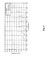
- a small peak will not be detected and will be aligned by its nominal position relative previous peak if no peak is found in the qualify window. This principle is shown in Fig. 4 .
- the peaks are detected by finding or identifying zero crossings in the trigger signal. In this illustrated example is the lap time 50 ms and the signal is sampled at 10 kHz.
- the IR signal IR(n) is received from the A/D converter 19.
- the received signal IR(n) is fed to a time alignment circuit 28 adapted to perform a time alignment between the identified peaks and the at least one predetermined estimation function.
- the time alignment circuit 28 comprises a delay buffer 30, where each sample is delayed with about the width of a peak. This approximate peak width can be determined by means of a calibration process.
- the delayed signal is combined at a combiner 32 with the undelayed signal. Thereby, a signal containing the difference of a current sample and a sample delayed about the width of the peak is obtained.
- the combined signal or trig signal is filtered in a low-pass filter 34 and the filtered signal is supplied to a zero crossing identifier 36 adapted to identify the zero crossings in the trig signal (see Fig. 4 ).
- the peak detector is adapted to identify the maximum derivative of the measurement signal.
- a qualify and small peak detection logic 38 is adapted to qualify peaks and to detect small peaks.
- the peak qualification uses a predetermined threshold, which may depend on an actual signal-to-noise ratio and need to be sufficiently high to avoid false detection but sufficiently low to detect at least some of the peaks.
- Each detected peak D(n) is outputted from the qualify and small peak detection logic 38.
- the small peak detection is performed by using a nominal inter-peak distance Dist[], i.e. if a zero crossing is not detected the next peak is approximated to occur at a nominal distance from the last peak.
- each peak in the IR signal is seen as a scaled and translated nominal peak and the scale factor can be used as a measure of the intensity of the peak.
- the nominal peak is calculated and stored by time-alignment and waveform averaging during the calibration process. This average waveform is called a base function and its length must be selected such that channel crosstalk is avoided.
- the scale factor and offset are determined by minimizing the least square error between the actual peak, i.e. the measured peak, and the modelled peak, i.e. in this embodiment the at least one base function.
- the IR signal IR(n) is received from the A/D converter 19.
- the received signal IR(n) is fed to a delay buffer 40, where each sample is delayed about the width of a peak. This approximate peak width can be determined by means of a calibration process.
- the detected peak D(n) is fed from the qualify and small peak detection logic 38 and an index identifying the current base function is fed to the delay buffer 40.
- the index identifying the current base function is also supplied to a model function circuit 44.
- the model function circuit 44 comprises the above mentioned base functions and the appropriate base function, baseF[index].wav[], can be selected on basis of the index.
- the time aligned peak, peak [] is outputted from the delay buffer 40 and fed to an intensity estimator 42.
- the estimated intensity, k is determined by solving the normal equations from the over-determined equation system that can be derived from: min k , b ⁇ peak - k ⁇ wav - b ⁇ ⁇ 2
- the estimated intensity, k is outputted from the intensity estimator 42.
- the estimated intensities, k can be used to determined the concentration or partial pressure of the gas or gases in the measurement chamber 13.
- An alternative approach to the use of base functions is to inverse filtering the measurement signal (received from the A/D converter).
- the filtering of the hardware is H ( z ).
- Each stable filter has an inverse H -1 ( z ), and, thus, H ( z ) ⁇ H -1 ( z ) will constitute an identity mapping. Thereby, it is possible to re-create the input signal.
- the measurement signal is converted in the A/D converter and is applied to the inverse filter.
- an estimation of the base line is created using linear interpolation between two consecutive reference levels in the inverse filtered signal, the estimation of the base line is subtracted from the inverse filtered signal, and each intensity is calculated as a weighted sum of values of the base line corrected signal where the sum interval is controlled by the peak detector.
- the cross-talk between can be modelled.
- the measured intensity can be seen as a sum of pulse responses having different delays and amplitudes.
- the measurement signal is converted in the A/D converter and intensity is calculated as a weighted sum of values from the A/D signal where the sum interval is controlled by the peak detector.
- the signal comprising the calculated intensities is de-convoluted. Then, an estimation of the base line using a linear interpolation between two consecutive reference levels in the de-convoluted signal is made and the estimation of the baseline is subtracted from the de-convoluted signal.
- the optical filters 14a, 14b have to be synchronized with the peaks of the IR signal. This can be performed, for example, by arranging an "index opening" in the filter component 14, which provides the largest peak in the signal. This largest peak may, in turn, be used to for the synchronization.
- a filter wheel mask in sheet metal is applied on the wheel, which easily can be designed to obtain different peak patterns. For example, by designing the wheel with different spacing between the filter openings. Thereby, the peaks will occur at different distances from each other in the measurement signal and the synchronization can be made using the distance pattern.
- the filter wheel is designed such that the shortest distance occurs between two of the peaks.
- An alternative approach is to use a sequence of different distances.
- a magnetic field sensor e.g. a hall-effect sensor
- the motor comprises a rotor including a number of permanent magnets and a hall-effect sensor is adapted to transfer information to the control circuit when the rotor rotates. This is, for example, used to regulate the motor to ensure that a constant speed can be withheld. Irregularities in the magnetization of the rotor will entail different intervals between the transition time points at constant speed, i.e. there exists a pattern, d h , that can be measured and related to the specific positions of the individual optical filters of the filter wheel at a calibration.
- the vector, d h has the same length as the number of filters, N. If ⁇ constitutes a registration of the N latest distances and when the expression ⁇ ⁇ ⁇ - d h ⁇ ⁇ is minimized or small, a synchronization has been obtained.
- the filter openings can be designed such that they have different sizes.
- a synchronization can be achieved by calculating a least square error between respective peak and the modelled peak, i.e. in this embodiment the at least one base function, corresponding to the respective filter.
- the filter component 14 comprises five optical filters 14a
- the calculation is based on the assumption that the absorbance's can be added, i.e. if two or more gases absorb light for a given filter the absorbance's for the respective gases can be added up to obtain to total absorbance.
- This assumption is an approximation that is adequate for certain gas combinations, concentrations and filters but not for all.
- the absorption of the gases is large and the transmittance is close to zero, a large error propagation from transmittance via absorbance to the partial pressure may occur.
- Filters having a high degree of absorbance contribute to an unnecessary large measurement error, which manifests as a measurement error and measurement noise, for example, at high partial pressures of Desfluran (DES).
- This error can be reduced significantly by weighting the equations containing a large error (see eqt. 2) with a factor ⁇ ( a i ) being a function of measured absorbance.
- a factor ⁇ ( a i ) being a function of measured absorbance.
- This method provides a number of advantages. It is for example possible to continuously "disconnect" a filter when the absorbance is too high. Moreover, the measurement error and measurement noise can be reduced as well as the reliability of the identification of gases present in the gas mixture.
Landscapes
- Physics & Mathematics (AREA)
- Spectroscopy & Molecular Physics (AREA)
- Health & Medical Sciences (AREA)
- Life Sciences & Earth Sciences (AREA)
- Chemical & Material Sciences (AREA)
- Analytical Chemistry (AREA)
- Biochemistry (AREA)
- General Health & Medical Sciences (AREA)
- General Physics & Mathematics (AREA)
- Immunology (AREA)
- Pathology (AREA)
- Investigating Or Analysing Materials By Optical Means (AREA)
Claims (22)
- Système d'analyse de gaz (10) pour l'analyse de gaz respiratoires délivrés à un et reçus d'un mammifère, ledit système d'analyse de gaz comprenant
un émetteur de lumière (11) qui inclut un émetteur d'IR adapté à émettre au moins un faisceau de mesure (12), ledit émetteur de lumière étant agencé de manière à émettre ledit faisceau de mesure (12) dans un mélange de gaz incluant lesdits gaz respiratoires,
un composant de filtres (14) incluant un certain nombre de filtres (14a, 14b) ayant différentes plages de longueurs d'onde de transmission, ledit composant de filtres (14) étant agencé de façon à positionner lesdits filtres (14a, 14b) de telle manière que ledit au moins un faisceau de mesure (12) passe à travers ledit certain nombre de filtres (14a, 14b) un à la fois,
un récepteur de lumière incluant un détecteur d'IR (16) adapté à recevoir ledit faisceau de mesure (12) et à générer au moins un signal de mesure représentatif d'une énergie optique dudit faisceau de mesure (12), et
un circuit de traitement de signaux (20) adapté à recevoir ledit au moins un signal de mesure, dans lequel ledit système est caractérisé en ce que
ledit circuit de traitement de signaux (20) inclut :un détecteur de pics (22) adapté à identifier des pics dans ledit au moins un signal de mesure, chaque pic correspondant à un filtre dudit composant de filtres, etune unité d'estimation de mesure d'intensité (24) adaptée à déterminer une mesure d'intensité de chaque pic identifié en utilisant au moins une fonction d'estimation prédéterminée. - Système d'analyse de gaz selon la revendication 1, dans lequel ledit détecteur de pics (22) comprend en outre un circuit d'alignement temporel (28) adapté à effectuer un alignement temporel entre des pics identifiés et ladite au moins une fonction d'estimation prédéterminée.
- Système d'analyse de gaz selon la revendication 1 ou 2, dans lequel ledit détecteur de pics (22) est adapté à déterminer au moins une mesure de caractérisation de pic du signal de mesure et à utiliser ladite au moins une mesure de caractérisation de pic pour identifier lesdits pics.
- Système d'analyse de gaz selon la revendication 2 ou 3 lorsqu'elle dépend de la revendication 2, dans lequel ledit circuit d'alignement temporel (28) comprend
un tampon de retard (30) adapté à recevoir ledit signal de mesure et à retarder ledit signal d'une période prédéterminée ;
un combineur (32) adapté à combiner ledit signal retardé avec le signal de mesure pour créer un signal de différence ;
un identifiant de passage par le zéro (36) adapté à identifier un passage par le zéro dans ledit signal de différence et à délivrer une indication de détection de pic sur la base du passage par le zéro identifié. - Système d'analyse de gaz selon l'une quelconque des revendications précédentes 1 à 4, dans lequel ledit détecteur de pics (22) comprend en outre
une logique de qualification et de détection de petits pics (38) adaptée à qualifier des pics en utilisant un seuil prédéterminé, dans lequel des pics ayant une grandeur étant au-dessus dudit seuil sont qualifiés comme étant un pic ; et à détecter des petits pics en utilisant une distance inter-pics prédéterminée. - Système d'analyse de gaz selon l'une quelconque des revendications précédentes 1 à 5, dans lequel ladite unité d'estimation de mesure d'intensité (24) inclut :un tampon de retard (40) adapté à recevoir ledit signal de mesure, à retarder ledit signal d'une période prédéterminée, à recevoir l'indication de détection de pic dudit détecteur de pics, et à créer un pic temporellement aligné en utilisant ledit signal de mesure retardé et ladite indication de détection de pic ;un circuit de fonction de modèle (44) adapté à recevoir l'indication de détection de pic dudit détecteur de pics (22) et à sélectionner ladite au moins une fonction d'estimation prédéterminée décrivant au moins une partie dudit signal de mesure sur la base de ladite indication de détection de pic ; etun estimateur d'intensité (42) adapté à recevoir ladite fonction d'estimation prédéterminée et ledit pic temporellement aligné et à estimer une intensité de chaque pic en utilisant ladite fonction d'estimation prédéterminée et ledit pic temporellement aligné.
- Système d'analyse de gaz selon l'une quelconque des revendications précédentes 1 à 5, dans lequel ladite unité d'estimation de mesure d'intensité (24) comprend :un filtre inverse adapté à inverser un filtrage dudit signal de mesure ; etun estimateur d'intensité (42) adapté à :estimer une ligne de base en utilisant une interpolation entre des niveaux de référence dans ledit signal filtré ;soustraire ladite ligne de base estimée dudit signal filtré pour créer un signal corrigé en termes de ligne de base ; etcalculer l'intensité pour chaque pic en utilisant des valeurs dudit signal corrigé en termes de ligne de base.
- Système d'analyse de gaz selon l'une quelconque des revendications précédentes 1 à 5, dans lequel ladite unité d'estimation de mesure d'intensité (24) comprend :un estimateur d'intensité (42) adapté à :calculer l'intensité pour chaque pic en utilisant des valeurs dudit signal de mesure :dé-convoluer le signal contenant les intensités calculées ;estimer une ligne de base en utilisant une interpolation entre des niveaux de référence dans ledit signal dé-convolué ; etsoustraire l'estimation de la ligne de base du signal dé-convolué.
- Système d'analyse de gaz selon la revendication 6, dans lequel ledit estimateur d'intensité (42) est adapté à estimer ladite intensité pour chaque pic en résolvant

dans laquelle peak[] représente ledit pic temporellement aligné, k représente l'intensité estimée, wav[] représente la fonction d'estimation prédéterminée, et b est un décalage. - Système d'analyse de gaz selon l'une quelconque des revendications précédentes 1 à 9, comprenant en outre un analyseur adapté à analyser lesdites mesures d'intensité pour identifier au moins un gaz dudit mélange de gaz et/ou une concentration d'au moins un gaz dudit mélange de gaz.
- Système d'analyse de gaz selon la revendication 10, dans lequel ledit analyseur est adapté à
utiliser un système d'équations décrivant la relation entre la pression partielle de gaz dans la chambre de mesure et les absorbances mesurées, et
utiliser des facteurs de pondération pour des équations respectives dans ledit système étant une fonction d'au moins les absorbances mesurées. - Procédé d'analyse de gaz respiratoires délivrés à un et reçus d'un mammifère, ledit procédé comprenant les étapes de :émission (S100) d'au moins un faisceau de mesure dans un mélange de gaz incluant lesdits gaz respiratoires,positionnement (S101) d'un composant de filtres incluant un certain nombre de filtres ayant différentes plages de longueurs d'onde de transmission de telle manière que ledit au moins un faisceau de mesure passe à travers ledit certain nombre de filtres un à la fois,réception (S102) dudit faisceau de mesure après passage à travers ledit mélange de gaz et lesdits filtres,génération (S103) d'au moins un signal de mesure représentatif d'une énergie optique dudit faisceau de mesure,ledit procédé étant caractérisé par les étapes de :identification de pics (S104) dans ledit au moins un signal de mesure, chaque pic correspondant à un filtre dudit composant de filtres, etdétermination d'une mesure d'intensité de chaque pic identifié en utilisant au moins une fonction d'estimation prédéterminée (S105).
- Procédé selon la revendication 12, dans lequel ladite étape d'identification (S105) comprend l'étape d'exécution d'un alignement temporel entre des pics identifiés et ladite au moins une fonction d'estimation prédéterminée.
- Procédé selon la revendication 12 ou 13, dans lequel ladite étape d'identification (S105) comprend l'étape de détermination d'au moins une mesure de caractérisation de pic du signal de mesure et d'utilisation de ladite au moins une mesure de caractérisation de pic pour identifier lesdits pics.
- Procédé selon la revendication 13 ou 14 lorsqu'elle dépend de la revendication 13, dans lequel l'étape d'exécution d'un alignement temporel comprend les étapes de :retardement dudit signal de mesure d'une période prédéterminée ;combinaison dudit signal retardé avec le signal de mesure pour créer un signal de différence ;identification d'un passage par le zéro dans ledit signal de différence et délivrance d'une indication de détection de pic sur la base du passage par le zéro identifié.
- Procédé selon l'une quelconque des revendications précédentes 12 à 15, dans lequel l'étape d'identification de pics (S104) comprend en outre l'étape de :qualification de pics en utilisant un seuil, dans lequel des pics ayant une grandeur étant au-dessus dudit seuil sont qualifiés comme étant un pic ; etdétection de petits pics en utilisant une distance inter-pics prédéterminée.
- Procédé selon l'une quelconque des revendications précédentes 12 à 16, dans lequel l'étape de détermination d'une mesure d'intensité de chaque pic identifié (S105) comprend les étapes de :retardement dudit signal de mesure d'une période prédéterminée ;création d'un pic temporellement aligné en utilisant ledit signal de mesure retardé et ladite indication de détection de pic ;sélection de ladite au moins une fonction d'estimation prédéterminée décrivant au moins une partie dudit signal de mesure sur la base de ladite indication de détection de pic ; etestimation d'une intensité de chaque pic en utilisant ladite fonction d'estimation prédéterminée et ledit pic temporellement aligné.
- Procédé selon l'une quelconque des revendications précédentes 12 à 16, dans lequel l'étape de détermination d'une mesure d'intensité de chaque pic identifié (S105) comprend les étapes de :filtrage inverse dudit signal de mesure ;estimation d'une ligne de base en utilisant une interpolation entre des niveaux de référence dans ledit signal filtré ;soustraction de ladite ligne de base estimée dudit signal filtré pour créer un signal corrigé en termes de ligne de base ; etcalcul de l'intensité pour chaque pic en utilisant des valeurs dudit signal corrigé en termes de ligne de base.
- Procédé selon l'une quelconque des revendications précédentes 12 à 16, dans lequel l'étape de détermination d'une mesure d'intensité de chaque pic identifié (S105) comprend les étapes de :calcul de l'intensité pour chaque pic en utilisant des valeurs dudit signal mesuré ;dé-convolution du signal contenant les intensités calculées ,estimation d'une ligne de base en utilisant une interpolation entre des niveaux de référence dans ledit signal dé-convolué ; etsoustraction de l'estimation de la ligne de base du signal dé-convolué.
- Procédé selon la revendication 17, dans lequel l'étape d'estimation (S100) comprend l'étape d'estimation de ladite intensité pour chaque pic en résolvant

dans laquelle peak[] représente ledit pic temporellement aligné, k représente l'intensité estimée, wav[] représente la fonction d'estimation prédéterminée, et b est un décalage. - Procédé selon l'une quelconque des revendications précédentes 12 à 20, comprenant en outre l'étape d'analyse desdites mesures d'intensité pour identifier au moins un gaz dudit mélange de gaz et/ou une concentration d'au moins un gaz dudit mélange de gaz.
- Procédé selon la revendication 21, comprenant en outre les étapes de
utilisation d'un système d'équations décrivant la relation entre la pression partielle de gaz dans la chambre de mesure et les absorbances mesurées, et
utilisation de facteurs de pondération pour des équations respectives dans ledit système étant une fonction d'au moins les absorbances mesurées.
Applications Claiming Priority (1)
| Application Number | Priority Date | Filing Date | Title |
|---|---|---|---|
| SE0702471 | 2007-11-09 |
Publications (2)
| Publication Number | Publication Date |
|---|---|
| EP2065697A1 EP2065697A1 (fr) | 2009-06-03 |
| EP2065697B1 true EP2065697B1 (fr) | 2012-02-22 |
Family
ID=40328664
Family Applications (1)
| Application Number | Title | Priority Date | Filing Date |
|---|---|---|---|
| EP08167482A Active EP2065697B1 (fr) | 2007-11-09 | 2008-10-24 | Système de mesure de gaz |
Country Status (2)
| Country | Link |
|---|---|
| EP (1) | EP2065697B1 (fr) |
| AT (1) | ATE546725T1 (fr) |
Families Citing this family (5)
| Publication number | Priority date | Publication date | Assignee | Title |
|---|---|---|---|---|
| JP2013515963A (ja) | 2009-12-29 | 2013-05-09 | コーニンクレッカ フィリップス エレクトロニクス エヌ ヴィ | 治療上の設定に用いられる短縮された光経路のマイクロ分光計を持つガス測定モジュール |
| CN102768188A (zh) * | 2012-07-30 | 2012-11-07 | 山东建筑大学 | 一种医疗设备 |
| ES2877551T3 (es) | 2013-04-24 | 2021-11-17 | Fresenius Kabi Deutschland Gmbh | Procedimiento de funcionamiento de un dispositivo de control para controlar un dispositivo de infusión |
| US20200018735A1 (en) * | 2017-03-20 | 2020-01-16 | Koninklijke Philips N.V. | Respiration gas monitor with automated and nonobtrusive filter calibration |
| US11692934B2 (en) | 2020-07-23 | 2023-07-04 | Masimo Corporation | Solid-state spectrometer |
Family Cites Families (4)
| Publication number | Priority date | Publication date | Assignee | Title |
|---|---|---|---|---|
| US4692621A (en) | 1985-10-11 | 1987-09-08 | Andros Anlayzers Incorporated | Digital anesthetic agent analyzer |
| US4914719A (en) | 1989-03-10 | 1990-04-03 | Criticare Systems, Inc. | Multiple component gas analyzer |
| SE524086C2 (sv) * | 2001-10-30 | 2004-06-22 | Phase In Ab | Mäthuvud för gasanalysator |
| CN1877304B (zh) * | 2005-06-10 | 2010-04-28 | 深圳迈瑞生物医疗电子股份有限公司 | 单种麻醉气体类型编码识别的方法和装置 |
-
2008
- 2008-10-24 EP EP08167482A patent/EP2065697B1/fr active Active
- 2008-10-24 AT AT08167482T patent/ATE546725T1/de active
Also Published As
| Publication number | Publication date |
|---|---|
| EP2065697A1 (fr) | 2009-06-03 |
| ATE546725T1 (de) | 2012-03-15 |
Similar Documents
| Publication | Publication Date | Title |
|---|---|---|
| US20030109795A1 (en) | Method of analyzing components of alveolar breath | |
| US4370553A (en) | Contaminated sample gas analyzer and gas cell therefor | |
| EP1012573B1 (fr) | Analyseur de gaz isotopique | |
| CA2429733C (fr) | Mesure isotopique stable et procede de mesure spectroscopique | |
| US5376555A (en) | Method for testing breath alcohol with discrimination between alveolar and upper respiratory tract alcohol | |
| EP2065697B1 (fr) | Système de mesure de gaz | |
| US4083367A (en) | Method and apparatus for pulmonary function analysis | |
| EP2909329B1 (fr) | Methodes de detection infections bacteriennes | |
| US20230363665A1 (en) | Capnometer | |
| CN113899716B (zh) | 气体检测装置和方法 | |
| US11963757B2 (en) | Side-stream respiratory gas monitoring system | |
| JPH03115955A (ja) | ガス分析装置 | |
| EP0584519B1 (fr) | Méthode spectrophotométrique et spectrophotomètre pour réaliser la méthode | |
| CN110618108A (zh) | 一种呼出气体中内源性丙酮的检测系统及方法 | |
| CN100356162C (zh) | 基于光源调制测量气体浓度的方法和装置 | |
| WO2012099985A2 (fr) | Dispositif d'analyse de gaz de courant principal | |
| CN101874735B (zh) | 一种用于二氧化碳浓度计算的多参数补偿方法 | |
| US20140179809A1 (en) | Determination Of Location Of Bacterial Load In The Lungs | |
| WO1990004164A1 (fr) | Appareil d'analyse permettant d'identifier les agents anesthesiants et d'en detecter la contamination | |
| Jaffe et al. | Continuous monitoring of respiratory flow and CO2 | |
| US9885653B1 (en) | Device for the analysis of an anesthesia ventilation gas as well as anesthesia ventilator | |
| CN216646259U (zh) | 一种双模多种气体呼气分析仪 | |
| JP2003511700A (ja) | 特に呼気分析に対する示差気体測定法 | |
| WO2021067078A1 (fr) | Analyseur de gaz respiratoire et diviseur de faisceau pour celui-ci | |
| CN116256328A (zh) | 一种双模多种气体呼气分析仪及双模多种气体呼气分析方法 |
Legal Events
| Date | Code | Title | Description |
|---|---|---|---|
| PUAI | Public reference made under article 153(3) epc to a published international application that has entered the european phase |
Free format text: ORIGINAL CODE: 0009012 |
|
| AK | Designated contracting states |
Kind code of ref document: A1 Designated state(s): AT BE BG CH CY CZ DE DK EE ES FI FR GB GR HR HU IE IS IT LI LT LU LV MC MT NL NO PL PT RO SE SI SK TR |
|
| AX | Request for extension of the european patent |
Extension state: AL BA MK RS |
|
| 17P | Request for examination filed |
Effective date: 20091118 |
|
| AKX | Designation fees paid |
Designated state(s): AT BE BG CH CY CZ DE DK EE ES FI FR GB GR HR HU IE IS IT LI LT LU LV MC MT NL NO PL PT RO SE SI SK TR |
|
| GRAP | Despatch of communication of intention to grant a patent |
Free format text: ORIGINAL CODE: EPIDOSNIGR1 |
|
| GRAS | Grant fee paid |
Free format text: ORIGINAL CODE: EPIDOSNIGR3 |
|
| GRAA | (expected) grant |
Free format text: ORIGINAL CODE: 0009210 |
|
| AK | Designated contracting states |
Kind code of ref document: B1 Designated state(s): AT BE BG CH CY CZ DE DK EE ES FI FR GB GR HR HU IE IS IT LI LT LU LV MC MT NL NO PL PT RO SE SI SK TR |
|
| REG | Reference to a national code |
Ref country code: GB Ref legal event code: FG4D |
|
| REG | Reference to a national code |
Ref country code: CH Ref legal event code: EP |
|
| REG | Reference to a national code |
Ref country code: AT Ref legal event code: REF Ref document number: 546725 Country of ref document: AT Kind code of ref document: T Effective date: 20120315 |
|
| REG | Reference to a national code |
Ref country code: IE Ref legal event code: FG4D |
|
| REG | Reference to a national code |
Ref country code: DE Ref legal event code: R096 Ref document number: 602008013546 Country of ref document: DE Effective date: 20120419 |
|
| REG | Reference to a national code |
Ref country code: NL Ref legal event code: VDEP Effective date: 20120222 |
|
| LTIE | Lt: invalidation of european patent or patent extension |
Effective date: 20120222 |
|
| PG25 | Lapsed in a contracting state [announced via postgrant information from national office to epo] |
Ref country code: IS Free format text: LAPSE BECAUSE OF FAILURE TO SUBMIT A TRANSLATION OF THE DESCRIPTION OR TO PAY THE FEE WITHIN THE PRESCRIBED TIME-LIMIT Effective date: 20120622 Ref country code: NO Free format text: LAPSE BECAUSE OF FAILURE TO SUBMIT A TRANSLATION OF THE DESCRIPTION OR TO PAY THE FEE WITHIN THE PRESCRIBED TIME-LIMIT Effective date: 20120522 Ref country code: LT Free format text: LAPSE BECAUSE OF FAILURE TO SUBMIT A TRANSLATION OF THE DESCRIPTION OR TO PAY THE FEE WITHIN THE PRESCRIBED TIME-LIMIT Effective date: 20120222 Ref country code: HR Free format text: LAPSE BECAUSE OF FAILURE TO SUBMIT A TRANSLATION OF THE DESCRIPTION OR TO PAY THE FEE WITHIN THE PRESCRIBED TIME-LIMIT Effective date: 20120222 Ref country code: NL Free format text: LAPSE BECAUSE OF FAILURE TO SUBMIT A TRANSLATION OF THE DESCRIPTION OR TO PAY THE FEE WITHIN THE PRESCRIBED TIME-LIMIT Effective date: 20120222 |
|
| PG25 | Lapsed in a contracting state [announced via postgrant information from national office to epo] |
Ref country code: FI Free format text: LAPSE BECAUSE OF FAILURE TO SUBMIT A TRANSLATION OF THE DESCRIPTION OR TO PAY THE FEE WITHIN THE PRESCRIBED TIME-LIMIT Effective date: 20120222 Ref country code: BE Free format text: LAPSE BECAUSE OF FAILURE TO SUBMIT A TRANSLATION OF THE DESCRIPTION OR TO PAY THE FEE WITHIN THE PRESCRIBED TIME-LIMIT Effective date: 20120222 Ref country code: PT Free format text: LAPSE BECAUSE OF FAILURE TO SUBMIT A TRANSLATION OF THE DESCRIPTION OR TO PAY THE FEE WITHIN THE PRESCRIBED TIME-LIMIT Effective date: 20120622 Ref country code: GR Free format text: LAPSE BECAUSE OF FAILURE TO SUBMIT A TRANSLATION OF THE DESCRIPTION OR TO PAY THE FEE WITHIN THE PRESCRIBED TIME-LIMIT Effective date: 20120523 Ref country code: LV Free format text: LAPSE BECAUSE OF FAILURE TO SUBMIT A TRANSLATION OF THE DESCRIPTION OR TO PAY THE FEE WITHIN THE PRESCRIBED TIME-LIMIT Effective date: 20120222 |
|
| REG | Reference to a national code |
Ref country code: AT Ref legal event code: MK05 Ref document number: 546725 Country of ref document: AT Kind code of ref document: T Effective date: 20120222 |
|
| PG25 | Lapsed in a contracting state [announced via postgrant information from national office to epo] |
Ref country code: CY Free format text: LAPSE BECAUSE OF FAILURE TO SUBMIT A TRANSLATION OF THE DESCRIPTION OR TO PAY THE FEE WITHIN THE PRESCRIBED TIME-LIMIT Effective date: 20120222 |
|
| PG25 | Lapsed in a contracting state [announced via postgrant information from national office to epo] |
Ref country code: PL Free format text: LAPSE BECAUSE OF FAILURE TO SUBMIT A TRANSLATION OF THE DESCRIPTION OR TO PAY THE FEE WITHIN THE PRESCRIBED TIME-LIMIT Effective date: 20120222 Ref country code: DK Free format text: LAPSE BECAUSE OF FAILURE TO SUBMIT A TRANSLATION OF THE DESCRIPTION OR TO PAY THE FEE WITHIN THE PRESCRIBED TIME-LIMIT Effective date: 20120222 Ref country code: SI Free format text: LAPSE BECAUSE OF FAILURE TO SUBMIT A TRANSLATION OF THE DESCRIPTION OR TO PAY THE FEE WITHIN THE PRESCRIBED TIME-LIMIT Effective date: 20120222 Ref country code: EE Free format text: LAPSE BECAUSE OF FAILURE TO SUBMIT A TRANSLATION OF THE DESCRIPTION OR TO PAY THE FEE WITHIN THE PRESCRIBED TIME-LIMIT Effective date: 20120222 Ref country code: RO Free format text: LAPSE BECAUSE OF FAILURE TO SUBMIT A TRANSLATION OF THE DESCRIPTION OR TO PAY THE FEE WITHIN THE PRESCRIBED TIME-LIMIT Effective date: 20120222 Ref country code: CZ Free format text: LAPSE BECAUSE OF FAILURE TO SUBMIT A TRANSLATION OF THE DESCRIPTION OR TO PAY THE FEE WITHIN THE PRESCRIBED TIME-LIMIT Effective date: 20120222 Ref country code: SE Free format text: LAPSE BECAUSE OF FAILURE TO SUBMIT A TRANSLATION OF THE DESCRIPTION OR TO PAY THE FEE WITHIN THE PRESCRIBED TIME-LIMIT Effective date: 20120222 |
|
| PG25 | Lapsed in a contracting state [announced via postgrant information from national office to epo] |
Ref country code: SK Free format text: LAPSE BECAUSE OF FAILURE TO SUBMIT A TRANSLATION OF THE DESCRIPTION OR TO PAY THE FEE WITHIN THE PRESCRIBED TIME-LIMIT Effective date: 20120222 Ref country code: IT Free format text: LAPSE BECAUSE OF FAILURE TO SUBMIT A TRANSLATION OF THE DESCRIPTION OR TO PAY THE FEE WITHIN THE PRESCRIBED TIME-LIMIT Effective date: 20120222 |
|
| PLBE | No opposition filed within time limit |
Free format text: ORIGINAL CODE: 0009261 |
|
| STAA | Information on the status of an ep patent application or granted ep patent |
Free format text: STATUS: NO OPPOSITION FILED WITHIN TIME LIMIT |
|
| 26N | No opposition filed |
Effective date: 20121123 |
|
| PG25 | Lapsed in a contracting state [announced via postgrant information from national office to epo] |
Ref country code: AT Free format text: LAPSE BECAUSE OF FAILURE TO SUBMIT A TRANSLATION OF THE DESCRIPTION OR TO PAY THE FEE WITHIN THE PRESCRIBED TIME-LIMIT Effective date: 20120222 |
|
| PGFP | Annual fee paid to national office [announced via postgrant information from national office to epo] |
Ref country code: ES Payment date: 20121129 Year of fee payment: 5 |
|
| REG | Reference to a national code |
Ref country code: DE Ref legal event code: R097 Ref document number: 602008013546 Country of ref document: DE Effective date: 20121123 |
|
| PG25 | Lapsed in a contracting state [announced via postgrant information from national office to epo] |
Ref country code: ES Free format text: LAPSE BECAUSE OF FAILURE TO SUBMIT A TRANSLATION OF THE DESCRIPTION OR TO PAY THE FEE WITHIN THE PRESCRIBED TIME-LIMIT Effective date: 20120602 |
|
| PG25 | Lapsed in a contracting state [announced via postgrant information from national office to epo] |
Ref country code: BG Free format text: LAPSE BECAUSE OF FAILURE TO SUBMIT A TRANSLATION OF THE DESCRIPTION OR TO PAY THE FEE WITHIN THE PRESCRIBED TIME-LIMIT Effective date: 20120522 |
|
| PG25 | Lapsed in a contracting state [announced via postgrant information from national office to epo] |
Ref country code: TR Free format text: LAPSE BECAUSE OF FAILURE TO SUBMIT A TRANSLATION OF THE DESCRIPTION OR TO PAY THE FEE WITHIN THE PRESCRIBED TIME-LIMIT Effective date: 20120222 |
|
| PG25 | Lapsed in a contracting state [announced via postgrant information from national office to epo] |
Ref country code: HU Free format text: LAPSE BECAUSE OF FAILURE TO SUBMIT A TRANSLATION OF THE DESCRIPTION OR TO PAY THE FEE WITHIN THE PRESCRIBED TIME-LIMIT Effective date: 20081024 |
|
| REG | Reference to a national code |
Ref country code: FR Ref legal event code: PLFP Year of fee payment: 9 |
|
| REG | Reference to a national code |
Ref country code: FR Ref legal event code: PLFP Year of fee payment: 10 |
|
| REG | Reference to a national code |
Ref country code: FR Ref legal event code: PLFP Year of fee payment: 11 |
|
| REG | Reference to a national code |
Ref country code: DE Ref legal event code: R082 Ref document number: 602008013546 Country of ref document: DE Representative=s name: ZACCO LEGAL RECHTSANWALTSGESELLSCHAFT MBH, DE Ref country code: DE Ref legal event code: R082 Ref document number: 602008013546 Country of ref document: DE Representative=s name: ZACCO PATENTANWALTS- UND RECHTSANWALTSGESELLSC, DE Ref country code: DE Ref legal event code: R081 Ref document number: 602008013546 Country of ref document: DE Owner name: MASIMO CORPORATION, IRVINE, US Free format text: FORMER OWNER: PHASEIN AB, DANDERYD, SE |
|
| REG | Reference to a national code |
Ref country code: GB Ref legal event code: 732E Free format text: REGISTERED BETWEEN 20181018 AND 20181024 |
|
| REG | Reference to a national code |
Ref country code: DE Ref legal event code: R082 Ref document number: 602008013546 Country of ref document: DE Representative=s name: ZACCO LEGAL RECHTSANWALTSGESELLSCHAFT MBH, DE |
|
| PGFP | Annual fee paid to national office [announced via postgrant information from national office to epo] |
Ref country code: ES Payment date: 20221001 Year of fee payment: 5 |
|
| P01 | Opt-out of the competence of the unified patent court (upc) registered |
Effective date: 20230601 |
|
| REG | Reference to a national code |
Ref country code: DE Ref legal event code: R082 Ref document number: 602008013546 Country of ref document: DE |
|
| PGFP | Annual fee paid to national office [announced via postgrant information from national office to epo] |
Ref country code: GB Payment date: 20250904 Year of fee payment: 18 |
|
| PGFP | Annual fee paid to national office [announced via postgrant information from national office to epo] |
Ref country code: FR Payment date: 20250908 Year of fee payment: 18 |
|
| PGFP | Annual fee paid to national office [announced via postgrant information from national office to epo] |
Ref country code: IE Payment date: 20250909 Year of fee payment: 18 |
|
| REG | Reference to a national code |
Ref country code: CH Ref legal event code: U11 Free format text: ST27 STATUS EVENT CODE: U-0-0-U10-U11 (AS PROVIDED BY THE NATIONAL OFFICE) Effective date: 20251101 |
|
| PGFP | Annual fee paid to national office [announced via postgrant information from national office to epo] |
Ref country code: LU Payment date: 20251016 Year of fee payment: 18 |
|
| PGFP | Annual fee paid to national office [announced via postgrant information from national office to epo] |
Ref country code: DE Payment date: 20250902 Year of fee payment: 18 |
|
| PGFP | Annual fee paid to national office [announced via postgrant information from national office to epo] |
Ref country code: MC Payment date: 20251002 Year of fee payment: 18 |
|
| PGFP | Annual fee paid to national office [announced via postgrant information from national office to epo] |
Ref country code: CH Payment date: 20251101 Year of fee payment: 18 |
|
| PGFP | Annual fee paid to national office [announced via postgrant information from national office to epo] |
Ref country code: MT Payment date: 20251017 Year of fee payment: 18 |