EP2065712A2 - Unité de surveillance d'écoulement - Google Patents
Unité de surveillance d'écoulement Download PDFInfo
- Publication number
- EP2065712A2 EP2065712A2 EP08018356A EP08018356A EP2065712A2 EP 2065712 A2 EP2065712 A2 EP 2065712A2 EP 08018356 A EP08018356 A EP 08018356A EP 08018356 A EP08018356 A EP 08018356A EP 2065712 A2 EP2065712 A2 EP 2065712A2
- Authority
- EP
- European Patent Office
- Prior art keywords
- line
- mixing block
- conduit
- piece
- mixing
- Prior art date
- Legal status (The legal status is an assumption and is not a legal conclusion. Google has not performed a legal analysis and makes no representation as to the accuracy of the status listed.)
- Withdrawn
Links
Images


Classifications
-
- G—PHYSICS
- G01—MEASURING; TESTING
- G01P—MEASURING LINEAR OR ANGULAR SPEED, ACCELERATION, DECELERATION, OR SHOCK; INDICATING PRESENCE, ABSENCE, OR DIRECTION, OF MOVEMENT
- G01P13/00—Indicating or recording presence, absence, or direction, of movement
- G01P13/008—Indicating or recording presence, absence, or direction, of movement by using a window mounted in the fluid carrying tube
Definitions
- the invention relates to a flow overgrowth unit for controlling an air flow in an oil-air system.
- oil-air systems are used, for example, for distribution of lubricant, for example, to supply lubricant to multiple lubrication points.
- the object of the present invention is to enable a simplified control of the air flow in an oil-air system and in particular to provide a cheaper or / and more compact monitoring unit.
- a flow overgrowth unit which is designed as a line adapter with the features of claim 1, a mixing block with the features of claim 8 or a progressive distributor system with the features of claim 15.
- the intermediate line piece has a first and a second line connection and at least one transparent wall section.
- this allows easy control without external power supply and without defective components.
- this has Conduit adapter on a size that does not exceed that of a common line or at least not significantly.
- a simple optical control of the air flow is made possible, for example, by the fact that flow lines, vortices, air or gas connections or the like can be observed through the transparent wall section, wherein their movement in the flow direction can be detected. This advantageously allows a simple visual check whether the transported in the line oil-air mixture is transported as intended through the line.
- the intermediate line piece according to the invention is not only suitable for installation in an oil-air line, but can also be used generally in a line for a multi-phase fluid.
- the various phases may comprise both solid and liquid or gaseous phases.
- the transparent portion is formed, for example, by transparent material.
- the entire intermediate line piece may be made of a transparent material, for example a plastic or a plastic mixture.
- the section can be a section of the line intermediate piece arranged in the direction of flow through the line intermediate piece.
- the transparent wall section extends only in a partial region of the intermediate line piece over a part of its circumference.
- the intermediate line piece has a first and a second line connection, which are configured, for example, as a screw, plug-in or latching connection, preferably as a quick-action coupling.
- the first and the second line connection are integrated in particular in a body of the intermediate line piece, which is preferably a metal body. However, it can also be used a plastic body.
- an at least partially transparent conduit element is used in the line spacer in flow communication with the line connections.
- This is in particular a pipe.
- this at least two-piece design allows a particularly stable configuration of the intermediate line piece as a connection between two lines to be connected thereto at the same time good transparency of the line element.
- the intermediate line piece is made of a metal, while the at least partially transparent line member is made of plastic or glass.
- the line element can be completely transparent. However, it may also be provided only a transparent portion with respect to a flow direction and / or a limited to a part of the circumference of the conduit member transparent portion.
- the conduit intermediate piece is designed essentially as a sleeve.
- the intermediate line piece on at least one viewing window, which is arranged such that at least a transparent portion of the conduit element is visible through the viewing window.
- the window is, for example, as a slot, slot or the like.
- the viewing window allows good visual control of flow in the conduit interface while providing good protection of the transparent conduit member through the conduit interface.
- this allows a largely encapsulated arrangement of the transparent conduit element, which minimizes in particular the risk of breakage of the conduit element at least.
- the control of a flow in the conduit intermediate piece can be improved according to the invention if the conduit intermediate piece at least one illumination opening different from the viewing window is at least indirectly Has lighting of the conduit element.
- an illumination opening arranged substantially opposite the viewing window can be provided for this purpose.
- the illumination opening can also be arranged so that a straight passage of light through the illumination opening and the viewing window is not possible. This preferably allows accurate observation of the flow based on scattering centers moving with the flow.
- the scattering centers are formed, for example, by phase boundaries. Due to the lack of directly passing light, the light scattered by the scattering centers is clearly visible.
- the illumination opening and / or the viewing window can be provided, for example, as bores in the particular sleeve-shaped intermediate line piece.
- the line element is inserted into a particular concentrically arranged in the line spacer bore. This allows for easy assembly and / or simple production.
- line adapter and line element are two concentric with each other inserted sleeve-shaped elements.
- a packaging of the intermediate line piece can be simplified according to the invention in that the line element is mounted by provided in the line spacer sealing elements.
- sealing elements for example, O-seals or the like. Provided. These are arranged for example in a groove within the pipe intermediate piece.
- the sealing elements are arranged adjacent to the line connections.
- An inner diameter of the sealing elements is in particular dimensioned so that the conduit element frictionally fixed in the intermediate line piece is. This allows it to be used for mounting without being able to fall out of the line adapter by itself.
- the line element can be inserted longitudinally in its direction of flow into the intermediate line piece, wherein the line element can be secured against displacement by connectable connection pieces through the line connections.
- This can be achieved, for example, in that an end face of the connecting pieces comes to lie in each case on an end face of the line element in a screwed-in state of the connecting pieces.
- the opposite end faces may be formed in particular as a sealing seats.
- the invention further relates to a mixing block for mixing at least two fluids, in particular for mixing oil and compressed air, wherein the mixing block has at least a first input for a first fluid and at least a second input for a second fluid, which inputs in at least one line of the mixing block open, which is in flow communication with at least one outlet of the mixing block, wherein the at least one conduit has at least one transparent wall portion.
- this allows both a control of material transport through the mixing block and a control of a composition of the material of at least the first fluid and the second fluid, in particular of oil and compressed air.
- more than two inputs may be provided so that more than two fluids or multiple streams are miscible.
- the transparent wall section of the mixing block is for example at least partially made of a transparent material.
- the entire mixing block can be made of a transparent plastic or a transparent plastic mixture.
- it can also be provided to insert a transparent wall section in an otherwise opaque mixing block.
- the mixing block has exactly one with exactly one output related line, which can serve to supply, for example, a lubrication point with an oil-compressed air mixture.
- the mixing block has at least two, preferably three or more lines, of which at least one, preferably all, have a transparent wall section.
- the mixing block has six similar lines, which may each be provided to supply one or more lubrication point.
- similar lines for example, only a portion of the lines for a mixture of at least two fluids, in particular oil and compressed air, and another part of the lines may be provided for example for the passage of air or oil.
- the mixing block has at least one viewing window which is arranged such that the transparent wall section of the at least one line can be viewed.
- This allows a possible closed construction of the mixing block and the best possible mechanical protection of at least one line.
- This embodiment is particularly favorable when the transparent wall portion of the at least one line is made of a material such as glass or plastic.
- the mixing block is made of a metal, for example.
- the production of metal allows a robust design of the inputs and the at least one output, in particular as screw, plug, snap-in connections or quick-release connections.
- a particularly non-transparent plastic can be used.
- the at least one viewing window is formed, for example, by a bore, in particular a long hole, in the mixing block. This allows a production of the mixing block of a solid material, in particular a metal block.
- the sensitivity of the visual control can be improved if the mixing block has at least one illumination opening different from the viewing window, which is arranged such that the transparent wall section of the at least one line of the mixing block can be illuminated at least indirectly by the illumination opening.
- the illumination opening is arranged with respect to the line substantially opposite to the viewing window. This can be achieved, for example, by drilling through the mixing block.
- the at least one illumination opening is arranged so that a rectilinear transillumination of the illumination opening and viewing window is not possible.
- the illumination opening is arranged with respect to the line approximately radially to the line 90 ° offset to a radial viewing axis of the viewing window on the line.
- the at least one line has at least one at least partially transparent conduit element which is inserted in the mixing block, in particular into a bore.
- the at least one conduit is formed by a bore guided into the block from an end face of the mixing block. Radially to this hole can open a viewing window or the associated viewing window channel in this line.
- the transparent conduit element is inserted into the corresponding bore.
- the transparent conduit element is, for example, a glass or plastic tube.
- the whole Conduit made of a transparent material. However, it can also be provided to configure only a longitudinal section and / or only a peripheral section of the conduit element transparent.
- the fabrication of the mixing block can be further simplified if the conduit element mounted by provided in the mixing block sealing elements.
- the line element is in particular fixed by friction in the mixing block.
- this can therefore be plugged into the corresponding hole provided for assembly, but not fall out by itself.
- the line element can be inserted into the mixing block along its direction of flow, wherein the line element can be secured against displacement by means of a connection piece which can be connected to a connection of the mixing block assigned to the line element.
- a connection piece which can be connected to a connection of the mixing block assigned to the line element.
- the conduit member is inserted into the bore up to a heel provided in the bore and then secured with the fitting in which an end face of the fitting abuts an end face of the conduit member.
- the opposite end faces can be configured in each case as sealing surfaces.
- a fixation can also be provided by a separate securing ring, for example a threaded ring, which is inserted into the bore before the connection piece is connected.
- a snap ring or a latch or the like can be used instead of a screw ring.
- the invention also relates to a progressive distributor system for distributing an oil-air mixture with at least one mixing block according to one of the embodiments described above.
- the progressive distributor system has in particular a connection for a first fluid, in particular oil, and at least one connection for a second fluid, in particular compressed air, on.
- the progressive distributor system preferably comprises a plurality of line connections for supplying a plurality of lubrication points.
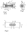
- FIG. 1 illustrated line adapter 1 is provided as a flow overgrowth unit for installation in an oil-air line, not shown, and has a first port 2, which serves as an inlet and a second port 3, which serves as an outlet.
- a body 4 of the conduit intermediate piece 1 according to the invention is designed substantially sleeve-shaped with a central bore 5.
- the body 4 is made of a metal.
- a glass tube 6 is inserted, which forms a transparent conduit element 7.
- a viewing window bore 9 is provided, through which a viewing window 10 and a lighting opening 11 are formed.
- the line spacer 1 thus has a transparent wall portion 12, which is formed by the glass tube 6.
- an oil-air mixture 13 flows through the line spacer 1, wherein vortex and / or phase boundaries 14 are transported in the flow direction 8 through the line spacer 1 and can be observed through the viewing window 10 through the glass tube 6 therethrough. In this way, it is possible to control whether the oil-air mixture 13 is flowing or whether there is possibly a stoppage, which indicates a generally undesirable line closure.
- sealing elements 15 adjacent to the terminals 2, 3 are provided. This makes it possible for the glass tube 6 to be inserted, for example, through the outlet 3 into the conduit intermediate piece 1 in order to be fixed there in a frictionally engaged manner.
- viewing window 10 and illumination opening 11 may not be aligned at an angle of 180 °, but at an angle of, for example, 90 ° to each other.
- a fixation of the glass tube 6 in the line spacer 1 can also be supported by the fact that end faces of the glass tube 6 are secured by not shown and screwed into the terminals 2, 3 or terminals against displacement along the flow direction 8.
- the in Fig. 1 shown longitudinal section corresponds to the section along a line AA, which in the in Fig. 2 illustrated cross section is located.
- This cross-section shows the sleeve-shaped body 4 of the conduit intermediate piece 1 and the glass tube 6 inserted therein. Furthermore, a connection 2 and a sealing element 15 are visible. All said elements are arranged concentrically with each other.
- the operation of the viewing window 10 is also in the in Fig. 3 shown top view of the line spacer 1 shown.
- the viewing window 10 is arranged in the sleeve-shaped body 4 of the line spacer 1, wherein the body 4 allows good mechanical protection of only partially visible through the window 10 glass tube 6.
- the body 4 allows good mechanical protection of only partially visible through the window 10 glass tube 6.
- the in Fig. 4 illustrated mixing block 17 has, as a flow overgrowth unit, a number of connections 2, which are provided for the outlet of an oil-air mixture.
- the mixing block 17 has an inlet, not shown, for oil and an inlet, not shown, for compressed air.
- the various terminals 2 are each associated with a line, not shown, which are in communication with the first input for the oil and the second input for the compressed air.
- These lines, not shown, are substantially below the viewing window 10, which serve a visual control of a flow of the oil-air mixture.
- an illumination opening 11 is provided, which is formed by a bore 18 which extends parallel to an outer edge 19 of the mixing block 17 longitudinally through the mixing block 17.
- FIG. 5 For a better overview of the mixing block 17 in Fig. 5 shown in a plan view.
- the viewing window 10 and the outlets 2 can be seen.
- six different inputs 20 are provided for a supply of oil.
- a supply of compressed air takes place via a compressed air connection 21.
- respective overflow valves 22 are provided adjacent to the viewing windows. Through the viewing window 10, in turn, vortex or phase boundaries 14 can be observed and thus determined whether a flow through the corresponding different ports 2 is present.
- the glass tubes 6 are in the in Fig. 6 shown front view of the mixing block 17 also to recognize.
- the glass tubes 6 are each attached to an associated connection bore 23.
- the illumination opening 11 is in Fig. 7 clarified.
- the illumination opening 11 is arranged such that light incident thereon falls on the glass tube 6 shown so that light scattered at vortices or phase boundaries 14 can be observed through the viewing window bore 9 shown in dashed lines.
- a flow course within the mixing block 17 is best in the representation of the cross section according to Fig. 8 to see.
- This cross section corresponds to a section along the line A'-A '.
- a line 24 is arranged, which is connected on the one hand with a compressed air connection 21 and on the other hand with an overflow valve 22 in flow communication.
- the conduit 24 has a glass tube 6 inserted therein, which is completely transparent. Therefore, an oil-air mixture 13 flowing through the conduit 24 in a flow direction 8 can be visually inspected through the inspection window 10.
- the bore 18 of the illumination opening 11 is provided.
- the line spacers or mixing blocks described in the preceding figures can, for example, in a progressive distributor system 25 according to Fig. 9 be used.
- a cascaded distribution of the oil and the compressed air takes place first as a mixture in a mixing block 17, which is preceded by an oil distributor 28.
- the mixing block 17 has viewing windows 10 for optical control. This allows a near-supply or near-distributor control of a flow of the oil-air mixture to be distributed.
- several line spacers 1 according to the invention are provided, which each have a viewing window 10. This also allows a reliable optical control of the desired material transport away from the oil or compressed air supply 26, 27. Via further distributor, the oil-air mixture finally reaches the lubrication points 29 to be supplied.
Landscapes
- Physics & Mathematics (AREA)
- General Physics & Mathematics (AREA)
- Indicating Or Recording The Presence, Absence, Or Direction Of Movement (AREA)
Applications Claiming Priority (1)
| Application Number | Priority Date | Filing Date | Title |
|---|---|---|---|
| DE200720016790 DE202007016790U1 (de) | 2007-11-29 | 2007-11-29 | Strömungs-Überwachungseinheit |
Publications (2)
| Publication Number | Publication Date |
|---|---|
| EP2065712A2 true EP2065712A2 (fr) | 2009-06-03 |
| EP2065712A3 EP2065712A3 (fr) | 2012-01-25 |
Family
ID=39105809
Family Applications (1)
| Application Number | Title | Priority Date | Filing Date |
|---|---|---|---|
| EP08018356A Withdrawn EP2065712A3 (fr) | 2007-11-29 | 2008-10-21 | Unité de surveillance d'écoulement |
Country Status (2)
| Country | Link |
|---|---|
| EP (1) | EP2065712A3 (fr) |
| DE (1) | DE202007016790U1 (fr) |
Families Citing this family (3)
| Publication number | Priority date | Publication date | Assignee | Title |
|---|---|---|---|---|
| DE102012010055A1 (de) | 2012-03-20 | 2013-09-26 | HyPneu Service GmbH | Einrichtung und Verfahren zur Überwachung der Dichtigkeit von druckluftverbrauchenden oder druckluftführenden pneumatischen Elementen |
| DE202019000970U1 (de) | 2019-02-25 | 2019-04-11 | Eberhard Zipplies | Strömungswächter |
| DE102019001406B4 (de) * | 2019-02-25 | 2022-05-25 | Eberhard Zipplies | Strömungswächter |
Family Cites Families (7)
| Publication number | Priority date | Publication date | Assignee | Title |
|---|---|---|---|---|
| US3384103A (en) * | 1966-03-03 | 1968-05-21 | Parker Hannifin Corp | Airline lubricator |
| US3618713A (en) * | 1969-12-12 | 1971-11-09 | Robert L Batchelor | Foam lubricating system and method |
| IT8122881V0 (it) * | 1981-09-14 | 1981-09-14 | Dropsa Spa | Apparecchiatura per il controllo della nebbia di lubrificazione. |
| JPH04142447A (ja) * | 1990-10-02 | 1992-05-15 | Ishikawajima Harima Heavy Ind Co Ltd | 潤滑油監視装置 |
| DE19956958A1 (de) * | 1999-11-16 | 2001-06-13 | Vogel Willi Ag | Verfahren und Vorrichtung zur Überwachung des Ölstroms einer Einrichtung zur Öl+Luft-Schmierung von Bauteilen |
| ITMI20030396A1 (it) * | 2003-03-04 | 2004-09-05 | Tiziano Barea | Dispositivo per il controllo di un flusso di un fluido che scorre in un condotto o fuoriesce da esso, quale un fluido lubrificante o di trattamento di manufatti, e metodo di controllo attuato da tale dispositivo. |
| GB0405596D0 (en) * | 2004-03-12 | 2004-04-21 | Imi Vision Ltd | Fluid flow monitoring device |
-
2007
- 2007-11-29 DE DE200720016790 patent/DE202007016790U1/de not_active Expired - Lifetime
-
2008
- 2008-10-21 EP EP08018356A patent/EP2065712A3/fr not_active Withdrawn
Also Published As
| Publication number | Publication date |
|---|---|
| EP2065712A3 (fr) | 2012-01-25 |
| DE202007016790U1 (de) | 2008-02-21 |
Similar Documents
| Publication | Publication Date | Title |
|---|---|---|
| WO2000071897A1 (fr) | Systeme de canalisation dote d'un filtre | |
| DE102017116417A1 (de) | Verteilervorrichtung | |
| DE202015100867U1 (de) | Leuchtenanordnung | |
| DE102013003926A1 (de) | Sanitäres Einbauteil, Innenschlauchanordnung für eine Sanitärarmatur und Sanitärarmatur | |
| EP1608902A1 (fr) | Dispositif pour reguler l'ecoulement de milieux liquides ou gazeux | |
| EP2065712A2 (fr) | Unité de surveillance d'écoulement | |
| DE102012212302C5 (de) | Sanitärarmatur | |
| EP0876564B1 (fr) | Raccord de tuyaux | |
| CH653426A5 (de) | Verbindungsvorrichtung fuer sanitaerinstallationen mit flexibler, beiderends anschlussmittel aufweisender verbindungsleitung. | |
| DE102009043024B4 (de) | Vorrichtung zum Verbinden zweier Rohrenden mit einem formschlüssig wirkenden Sicherungselement (Doppelkette) | |
| WO2009156107A1 (fr) | Raccord réducteur de tube en un matériau plastique | |
| DE102009031044B4 (de) | Anschluss einer sekundären Leitung einer Reinwasser-Hauptversorgungsleitung an ein Dialysegerät oder dergleichen | |
| EP0708209B1 (fr) | Assortiment d'armatures tubulaires pour les techniques relatives aux conduites d'eau, aux installations sanitaires, conduites de chauffage, de gaz etc | |
| DE102005002627A1 (de) | Duscheinrichtung | |
| DE102016208354A1 (de) | Filteranordnung | |
| DE102007033969B4 (de) | Vorrichtung zur Messung der Viskosität von Kunststoffschmelzen | |
| EP1097037B1 (fr) | Changeur de tamis avec equipement interchangeable associe | |
| EP2076702B1 (fr) | Vanne de régulation de débit | |
| DE202012100550U1 (de) | Verbindungsvorrichtung zum Verbinden von Leitungselementen | |
| EP1245909A2 (fr) | Dispositif de raccordement pour radiateur et radiateur | |
| DE102010040213B4 (de) | Druckschalter | |
| DE3532180C1 (en) | Device for shutting off a pipeline, especially a drinking-water line | |
| DE202019106638U1 (de) | Verbindungselement für Mehrkantrohre | |
| DE102020123432B4 (de) | Filter, insbesondere zum Abscheiden von Partikeln und/oder Gasen und/oder Flüssigkeiten aus einem Fluidstrom, insbesondere aus einem Druckluftstrom | |
| DE10233863A1 (de) | Anschlussblock für Sanitärarmaturen |
Legal Events
| Date | Code | Title | Description |
|---|---|---|---|
| PUAI | Public reference made under article 153(3) epc to a published international application that has entered the european phase |
Free format text: ORIGINAL CODE: 0009012 |
|
| AK | Designated contracting states |
Kind code of ref document: A2 Designated state(s): AT BE BG CH CY CZ DE DK EE ES FI FR GB GR HR HU IE IS IT LI LT LU LV MC MT NL NO PL PT RO SE SI SK TR |
|
| AX | Request for extension of the european patent |
Extension state: AL BA MK RS |
|
| PUAL | Search report despatched |
Free format text: ORIGINAL CODE: 0009013 |
|
| AK | Designated contracting states |
Kind code of ref document: A3 Designated state(s): AT BE BG CH CY CZ DE DK EE ES FI FR GB GR HR HU IE IS IT LI LT LU LV MC MT NL NO PL PT RO SE SI SK TR |
|
| AX | Request for extension of the european patent |
Extension state: AL BA MK RS |
|
| RIC1 | Information provided on ipc code assigned before grant |
Ipc: G01P 13/00 20060101AFI20111220BHEP |
|
| AKY | No designation fees paid | ||
| REG | Reference to a national code |
Ref country code: DE Ref legal event code: R108 |
|
| REG | Reference to a national code |
Ref country code: DE Ref legal event code: R108 Effective date: 20121004 |
|
| STAA | Information on the status of an ep patent application or granted ep patent |
Free format text: STATUS: THE APPLICATION IS DEEMED TO BE WITHDRAWN |
|
| 18D | Application deemed to be withdrawn |
Effective date: 20120726 |