EP2065725B1 - Ultraschallsystem und Verfahren zum Erzeugen eines BC-Mode-Bildes - Google Patents
Ultraschallsystem und Verfahren zum Erzeugen eines BC-Mode-Bildes Download PDFInfo
- Publication number
- EP2065725B1 EP2065725B1 EP08019747.8A EP08019747A EP2065725B1 EP 2065725 B1 EP2065725 B1 EP 2065725B1 EP 08019747 A EP08019747 A EP 08019747A EP 2065725 B1 EP2065725 B1 EP 2065725B1
- Authority
- EP
- European Patent Office
- Prior art keywords
- receive signals
- control signal
- mode image
- time ratio
- scan
- Prior art date
- Legal status (The legal status is an assumption and is not a legal conclusion. Google has not performed a legal analysis and makes no representation as to the accuracy of the status listed.)
- Not-in-force
Links
Images




Classifications
-
- A—HUMAN NECESSITIES
- A61—MEDICAL OR VETERINARY SCIENCE; HYGIENE
- A61B—DIAGNOSIS; SURGERY; IDENTIFICATION
- A61B8/00—Diagnosis using ultrasonic, sonic or infrasonic waves
-
- G—PHYSICS
- G01—MEASURING; TESTING
- G01S—RADIO DIRECTION-FINDING; RADIO NAVIGATION; DETERMINING DISTANCE OR VELOCITY BY USE OF RADIO WAVES; LOCATING OR PRESENCE-DETECTING BY USE OF THE REFLECTION OR RERADIATION OF RADIO WAVES; ANALOGOUS ARRANGEMENTS USING OTHER WAVES
- G01S7/00—Details of systems according to groups G01S13/00, G01S15/00, G01S17/00
- G01S7/52—Details of systems according to groups G01S13/00, G01S15/00, G01S17/00 of systems according to group G01S15/00
- G01S7/52017—Details of systems according to groups G01S13/00, G01S15/00, G01S17/00 of systems according to group G01S15/00 particularly adapted to short-range imaging
- G01S7/52023—Details of receivers
- G01S7/52025—Details of receivers for pulse systems
-
- G—PHYSICS
- G01—MEASURING; TESTING
- G01S—RADIO DIRECTION-FINDING; RADIO NAVIGATION; DETERMINING DISTANCE OR VELOCITY BY USE OF RADIO WAVES; LOCATING OR PRESENCE-DETECTING BY USE OF THE REFLECTION OR RERADIATION OF RADIO WAVES; ANALOGOUS ARRANGEMENTS USING OTHER WAVES
- G01S15/00—Systems using the reflection or reradiation of acoustic waves, e.g. sonar systems
- G01S15/88—Sonar systems specially adapted for specific applications
- G01S15/89—Sonar systems specially adapted for specific applications for mapping or imaging
- G01S15/8906—Short-range imaging systems; Acoustic microscope systems using pulse-echo techniques
- G01S15/8979—Combined Doppler and pulse-echo imaging systems
- G01S15/8988—Colour Doppler imaging
-
- G—PHYSICS
- G01—MEASURING; TESTING
- G01S—RADIO DIRECTION-FINDING; RADIO NAVIGATION; DETERMINING DISTANCE OR VELOCITY BY USE OF RADIO WAVES; LOCATING OR PRESENCE-DETECTING BY USE OF THE REFLECTION OR RERADIATION OF RADIO WAVES; ANALOGOUS ARRANGEMENTS USING OTHER WAVES
- G01S7/00—Details of systems according to groups G01S13/00, G01S15/00, G01S17/00
- G01S7/52—Details of systems according to groups G01S13/00, G01S15/00, G01S17/00 of systems according to group G01S15/00
- G01S7/52017—Details of systems according to groups G01S13/00, G01S15/00, G01S17/00 of systems according to group G01S15/00 particularly adapted to short-range imaging
- G01S7/52053—Display arrangements
- G01S7/52057—Cathode ray tube displays
- G01S7/5206—Two-dimensional coordinated display of distance and direction; B-scan display
- G01S7/52063—Sector scan display
-
- G—PHYSICS
- G01—MEASURING; TESTING
- G01S—RADIO DIRECTION-FINDING; RADIO NAVIGATION; DETERMINING DISTANCE OR VELOCITY BY USE OF RADIO WAVES; LOCATING OR PRESENCE-DETECTING BY USE OF THE REFLECTION OR RERADIATION OF RADIO WAVES; ANALOGOUS ARRANGEMENTS USING OTHER WAVES
- G01S7/00—Details of systems according to groups G01S13/00, G01S15/00, G01S17/00
- G01S7/52—Details of systems according to groups G01S13/00, G01S15/00, G01S17/00 of systems according to group G01S15/00
- G01S7/52017—Details of systems according to groups G01S13/00, G01S15/00, G01S17/00 of systems according to group G01S15/00 particularly adapted to short-range imaging
- G01S7/52085—Details related to the ultrasound signal acquisition, e.g. scan sequences
-
- A—HUMAN NECESSITIES
- A61—MEDICAL OR VETERINARY SCIENCE; HYGIENE
- A61B—DIAGNOSIS; SURGERY; IDENTIFICATION
- A61B8/00—Diagnosis using ultrasonic, sonic or infrasonic waves
- A61B8/08—Clinical applications
Definitions
- the present invention generally relates to ultrasound systems, and more particularly to an ultrasound system and a method for forming a BC-mode image.
- An ultrasound system has become an important and popular diagnostic tool due to its non-invasive and non-destructive nature.
- Modern high-performance ultrasound imaging diagnostic systems and techniques are commonly used to produce two- or three-dimensional images of internal features of patients.
- the ultrasound system may provide a BC-mode image indicating a blood flow or a motion of a target object, which is estimated by using a Doppler effect, on a B-mode image.
- the BC-mode image is a combination image comprising a B-mode image of a grey scale and a color flow image (i.e., C-mode image) indicating the blood flow or the motion of the target object.
- the BC-mode image may provide anatomical information as well as information regarding the blood flow or the motion of the target object.
- the conventional ultrasound image may form the B-mode image and the C-mode image with different frame rates and then combine the B-mode image with the C-mode image to thereby form the BC-mode image. Since the frame rate of the BC-mode may not be enough to obtain information regarding blood flow or the motion of the target object such as a cardiac muscle, the frame rate of the BC-mode must be improved such that motion information of the target object such as a cardiac, which is rapidly moved, can be accurately provided.
- a multi-mode ultrasonic images are formed by processing the ultrasonic echoes from a single transmit pulse in parallel to display both tissue and motion.
- short transmit bursts are employed to produce echo ensembles for tissue motion imaging.
- At least one sequence of echoes of the ensemble is also B mode processed for display of tissue structure.
- Preferably both the B mode and motion processing are performed in parallel.
- a substantially constant pulse repetition frequency reduces artifact development when imaging in the two modes from the same transmit pulse.
- the WO 2004/106969 A2 describes an ultrasonic diagnostic imaging system in which two planes of a volumetric region which are in different elevation planes are scanned in real time.
- the two planes are scanned with less than the maximum number of scanlines which the transducer (500) can transmit in a single plane.
- a user control enables the two planes to be moved laterally without moving the transducer probe.
- each image plane contains a color box depicting flow or motion in the same respective position in the image.
- the color boxes of the two images can be sized and positioned in tandem so that both are in the same corresponding area of the two images.
- a method is provided to simultaneously acquire two ultrasound images.
- a first set of ultrasound pulses are transmitted at a first frame rate utilizing a first mode of operation.
- the echoes from the first set of ultrasound pulses are received.
- a second set of ultrasound pulses are transmitted at a second frame rate utilizing a second mode of operation.
- the first and second frame rates are different.
- the first set of ultrasound pulses defines an entire image, while the second set of ultrasound pulses defines a partial image.
- the echoes from the second set of ultrasound pulses are received, and the echoes from the first and second sets of ultrasound pulses are displayed as a single image.
- XP01070193 discloses in ultrasound Color Doppler imaging, a grayscale B-mode image and a Doppler image representing velocities are overlaid to produce a color coded image of e.g. blood flow or myocardial movement. Normally, the B-mode and Doppler images are acquired at the same rate, resulting in trade offs between B-mode image quality and Doppler frame rate.
- a new scan sequencing technique for Color Doppler imaging is presented, where the B-mode image is acquired at a lower frame rate than the Doppler scan. This is achieved by splitting the B-mode image in subscans which are acquired in between multiple scans of the entire Doppler image. In this way, a full width B-mode image with high spatial resolution is kept while the temporal resolution of the velocity information is increased.
- Tissue Velocity Imaging TVI
- FIG. 1 is a block diagram showing an embodiment of an ultrasound system.
- the ultrasound system 100 includes a control unit 110, a transmit/receive unit 120, a storage unit 130, an image processing unit 140 and a display unit 150.
- the ultrasound system 110 further includes an input unit (not shown) to receive input information from a user.
- the input information may include setup information for setting a color box on a B-mode image, i.e., position and size information of the color box.
- the control unit 110 may be operable to control the formation of a BC-mode image in consideration of a time required to form a B-mode image and a time required to form a C-mode image.
- the control unit 110 may be further operable to control operations of the transmit/receive unit 120, the storage unit 130, the image processing unit 140 and the display unit 150.
- FIG. 2 is a block diagram showing an illustrative embodiment of the control unit 110.
- a time computing unit 111 may be operable to compute a time required to form a B-mode image ("first time") and a time required to form a C-mode image (“second time”).
- the first time (T B ) and the second time (Tc) may be computed by using the following equations (1) and (2).
- N B N B / PRF B
- T C N C ⁇ PS / PRF C
- N B the number of scan lines used to form the B-mode image
- PRF B represents a pulse repetition frequency used to form the B-mode image
- NC represents the number of the scan lines used to form the C-mode image
- PS represents a packet size indicating repetition times of transmitting and receiving an ultrasound beam along one scan line
- PRF C represents a pulse repetition frequency used to form the C-mode image.
- a ratio computing unit 112 may be operable to compute a time ratio of the first time T B to the second time Tc.
- a determining unit 113 may be operable to compare the time ratio with a preset critical value (e.g., 1) to check whether the time ratio excesses the critical value. If the time ratio excesses the critical value, the determining unit 113 may output first determination information containing the time ratio. On the contrary, if not, the determining unit 113 may output second determination information.
- a preset critical value e.g. 1
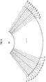
- a scan line group setting unit 114 may be operable to set a plurality of scan line groups as many as the time ratio indicated by the first determination information. For example, when the time ratio is "4," scan lines S 1 -S 64 illustrated in FIG. 3 may be divided into four scan line groups SG 1 , SG 2 , SG 3 and SG 4 , as follows.
- First scan line group SG 1 S 1 , S 5 , S 9 , S 13 , S 17 , ⁇ , S 53 , S 57 , S 61
- Second scan line group SG 2 S 2 , S 6 , S 10 , S 14 , S 18 , ⁇ , S 54 , S 58 , S 62
- Third scan line group SG 3 S 3 , S 7 , S 11 , S 15 , S 19 , ⁇ , S 55 , S 59 , S 63
- Fourth scan line group SG 4 S 4 , S 8 , S 12 , S 16 , S 20 , ⁇ , S 56 , S 60 , S 64
- a control signal generating unit 115 may be operable to generate a control signal for controlling transmission and reception of the ultrasound beam.
- the control signal may include a first control signal for controlling the formation of a B-mode image 210, i.e., a B-mode scan such that the ultrasound beam is transmitted are received along the scan lines S 1 -S 64 .
- the control signal may further include a second control signal for controlling the formation of the C-mode image, i.e., a C-mode scan such that the ultrasound beam is transmitted and received along scan lines S 10 to S 56 within a color box 220 set on the B-mode image 210 (see FIG. 3 ).
- the control signal also includes a third control signal for controlling the transmission and reception of the ultrasound beam such that the ultrasound beam for the B-mode image is alternately transmitted and received along scan lines included in the respective scan line groups.
- control signal generating unit 115 may be operable to generate a fourth control signal for a B-mode scan such that the ultrasound beam is transmitted along scan lines S 1 -S 9 and S 57 -S 64 , which do not belong to the color box 220.
- the transmit/receive unit 120 is operable to transmit the ultrasound beam along scan lines set in a target object and receive ultrasound echoes reflected from the target object in response to the control signal. If the first control signal is inputted from the control unit 110, the transmit/receive unit 120 may be operable to sequentially transmit the ultrasound beam along the scan lines S 1 -S 64 in response to the first control signal and receive ultrasound echoes reflected from the target object to thereby form receive signals corresponding to the scan lines S 1 -S 64 ("first receive signals") for a B-mode image.
- the first receive signals may include information associated with the scan lines, e.g., position information of the scan lines, position information of sampling points on the scan lines, data obtained at the sampling points and the like.
- the transmit/receive unit 120 may be operable to transmit the ultrasound beam along the scan lines S 10 -S 56 belonging to the color box 220 in response to the second control signal and receive ultrasound echoes reflected from the target object to thereby form receive signals corresponding to the scan lines S 10 -S 56 ("second receive signals") for the C-mode image.
- the second receive signals may include information associated with the scan lines S 10 -S 56 , e.g., position information of the scan lines, position information of sampling points on the scan lines, data obtained from the sampling points and the like.
- the transmit/receive unit 120 may be operable to transmit the ultrasound beam along the scan lines S 1 , S 5 , S 9 , S 13 , S 17 , ..., S 53 , S 57 and S 61 included in the first scan line group SG 1 and receive ultrasound echoes from the target object in response to the third control signal to thereby form receive signals corresponding to the scan lines included in the first scan line group SG 1 ("first scan line group receive signals").
- the first scan line group receive signals may include information associated with the scan lines of the first scan line group SG 1 , e.g., position information of the scan lines, position information of sampling points on the scan lines, data obtained from the sampling points and the like.
- the transmit/receive unit 120 may be operable to transmit the ultrasound beam along the scan lines S 10 -S 56 within the color box 220 and receive ultrasound echoes reflected from the target object in response to the second control signal to thereby form new second receive signals for a C-mode image.
- the transmit/receive unit 120 may be operable to transmit the ultrasound beam along the scan lines S 2 , S 6 , S 10 , S 14 , S 18 , ..., S 54 , S 58 and S 62 included in the second scan line group SG 2 and receive ultrasound echoes from the target object in response to the third control signal to thereby form receive signals corresponding to the scan lines included in the second scan line group SG 2 ("second scan line group receive signals").
- the second scan line group receive signals may include information associated with the scan lines of the first scan line group SG2, e.g., position information of the scan lines, position information of sampling points on the scan lines, data obtained from the sampling points and the like.
- the transmit/receive unit 120 may be operable to transmit the ultrasound beam along the scan lines S 10 -S 56 within the color box 220 and receive ultrasound echoes reflected from the target object in response to the second control signal to thereby form new second receive signals.
- the transmit/receive unit 120 may be operable to transmit the ultrasound beam along the scan lines S 3 , S 7 , S 11 , S 15 , S 19 , ..., S 55 , S 59 and S 63 included in the third scan line group SG 3 and receive ultrasound echoes from the target object in response to the third control signal to thereby form receive signals corresponding to the scan lines included in the third scan line group SG 3 ("third scan line group receive signals").
- the third scan line group receive signals may include information associated with the scan lines of the third scan line group SG 3 , e.g., position information of the scan lines, position information of sampling points on the scan lines, data obtained from the sampling points and the like.
- the transmit/receive unit 120 may be operable to transmit the ultrasound beam along the scan lines S 10 -S 56 within the color box 220 and receive ultrasound echoes reflected from the target object in response to the second control signal to thereby form new second receive signals.
- the transmit/receive unit 120 may be operable to transmit the ultrasound beam along the scan lines S 4 , S 8 , S 12 , S 16 , S 20 , ..., S 56 , S 60 and S 64 included in the fourth scan line group SG 4 and receive ultrasound echoes from the target object in response to the third control signal to thereby form receive signals corresponding to the scan lines included in the fourth scan line group SG 4 ("fourth scan line group receive signals").
- the fourth scan line group receive signals may include information associated with the scan lines of the fourth scan line group SG 4 , e.g., position information of the scan lines, position information of sampling points on the scan lines, data obtained from the sampling points and the like.
- the transmit/receive unit 120 may be operable to transmit the ultrasound beam along the scan lines S 10 -S 56 within the color box 220 and receive ultrasound echoes reflected from the target object in response to the second control signal to thereby form new second receive signals.
- the transmit/receive unit 120 may be operable to repeat the above process until an end request is inputted.
- the transmit/receive unit 120 may be operable to transmit the ultrasound beam along scan lines S 1 -S 9 and S 57 -S 64 , which are not within the color box 220 among the scan lines S1-S64, and receive ultrasound echoes reflected from the target object to thereby form receive signals corresponding to the scan lines S 1 -S 9 and S 57 -S 64 ("third receive signals").
- the third receive signals may contain information associated with the scan lines S 1 -S 9 and S 57 -S 64 , i.e., position information of the scan lines, position information of sampling points on the scan lines, data obtained at the sampling points and the like.
- the transmit/receive unit 120 may be operable to transmit the ultrasound beam along the scan lines S 10 -S 56 within the color box 220 and receive ultrasound echoes reflected from the target object in response to the second control signal to thereby form new second receive signals.
- the transmit/receive unit 120 may be operable to repeat the above process until an end request is inputted from the control unit 110.
- the storage unit 130 may sequentially store the first receive signals, the second receive signals, the first to fourth scan line group receive signals and the third receive signals.
- the image processing unit 140 may be operable to extract the first receive signals from the storage unit 130 and form a B-mode image based on the first receive signals.
- the image processing unit may operable to extract the second receive signals from the storage unit 130 and form a C-mode image based on the extracted second receive signals.
- the image processing unit 140 may be operable to combine the B-mode image with the C-mode image to form a BC-mode image.
- the image processing unit 140 may be operable to extract the first scan line group receive signals and first receive signals in which first receive signals corresponding to the scan lines S 1 , S 5 , S 9 , S 13 , S 17 , ..., S 53 , S 57 and S 61 included in the first scan line group SG 1 are excluded, and then update the first receive signals with the extracted first scan line group receive signals.
- the image processing unit 140 may be operable to form a B-mode image 310 based on the updated first receive signals, as illustrated in FIG. 4 .
- the image processing unit may extract the new second receive signals from the storage unit 130 and form a C-mode image based on the extracted second receive signals. Thereafter, the image processing unit 140 may be operable to combine the B-mode image 310 with the C-mode image to form a BC-mode image.
- the image processing unit 140 may be operable to extract the second scan line group receive signals and first receive signals excepting the receive signals corresponding to the scan lines included in the second scan line group SG 2 to update the first receive signals.
- the image processing unit 140 may be operable to form a B-mode image 320 based on the updated first receive signals, as illustrated in FIG. 5 .
- the image processing unit may extract the new second receive signals from the storage unit 130 and form a C-mode image based on the extracted new second receive signals. Thereafter, the image processing unit 140 may be operable to combine the B-mode image 320 with the C-mode image to form a BC-mode image.
- the image processing unit 140 may be operable to extract the third scan line group receive signals and first receive signals in which the receive signals corresponding to the scan lines included in the third scan line group SG 3 are excluded to update the first receive signals.
- the image processing unit 140 may be operable to form a B-mode image 330 based on the updated first receive signals, as illustrated in FIG. 6 .
- the image processing unit may extract the new second receive signals from the storage unit 130 and form a C-mode image based on the extracted second receive signals. Thereafter, the image processing unit 140 may be operable to combine the B-mode image 330 with the C-mode image to form a BC-mode image.
- the image processing unit 140 may be operable to extract the fourth scan line group receive signals and first receive signals in which the receive signals corresponding to the scan lines included in the fourth scan line group SG 4 are excluded to update the first receive signals.
- the image processing unit 140 may be operable to form a B-mode image 340 based on the updated first receive signals, as illustrated in FIG. 7 .
- the image processing unit may extract the new second receive signals from the storage unit 130 and form a C-mode image based on the extracted second receive signals. Thereafter, the image processing unit 140 may be operable to combine the B-mode image 340 with the C-mode image to form a BC-mode image.
- the image processing unit 140 may repeatedly carry out the above process until an end request is inputted from the control unit 110.
- the image processing unit 140 may extract the third receive signals and the first receive signals from the storage unit 130, and then from a B-mode image 350 based on the extracted third and first receive signals, as illustrated in FIG. 8 . Thereafter, the image processing unit 140 may extract the second receive signals and form a C-mode image based on the extracted second receive signals. The image processing unit 140 may combine the B-mode image with the C-mode image to form a BC-mode image.
- the display unit 150 may be operable to display the B-mode image and the BC-mode image formed in the image processing unit 140.
- the frame rate of the BC-mode image may be improved.
- an ultrasound image of a rapidly moving target object may be clearly provided.
Landscapes
- Engineering & Computer Science (AREA)
- Physics & Mathematics (AREA)
- Radar, Positioning & Navigation (AREA)
- Remote Sensing (AREA)
- Computer Networks & Wireless Communication (AREA)
- General Physics & Mathematics (AREA)
- Acoustics & Sound (AREA)
- Health & Medical Sciences (AREA)
- Life Sciences & Earth Sciences (AREA)
- Nuclear Medicine, Radiotherapy & Molecular Imaging (AREA)
- Molecular Biology (AREA)
- Pathology (AREA)
- Radiology & Medical Imaging (AREA)
- Biomedical Technology (AREA)
- Heart & Thoracic Surgery (AREA)
- Medical Informatics (AREA)
- Biophysics (AREA)
- Surgery (AREA)
- Animal Behavior & Ethology (AREA)
- General Health & Medical Sciences (AREA)
- Public Health (AREA)
- Veterinary Medicine (AREA)
- Ultra Sonic Daignosis Equipment (AREA)
Claims (10)
- Ultraschallsystem (100), welches Folgendes aufweist:eine Steuereinheit (110), die dafür vorgesehen ist, ein erstes Steuersignal für einen B-Modus-Scan und ein zweites Steuersignal für einen C-Modus-Scan zu erzeugen;eine Eingabeeinheit, die dafür vorgesehen ist, Informationen bezüglich einer Farbbox (220) zu empfangen, um eine Farbbox (220) einzustellen;eine Übertragungs-/Empfangs-Einheit (120), die auf die ersten und zweiten Steuersignale reagiert und in der Lage ist, Ultraschallsignale entlang einer Vielzahl von in einem Zielobjekt eingestellten Scanlinien zu übertragen und Empfangssignale basierend auf den von dem Zielobjekt reflektierten Ultraschallechosignalen zu erzeugen, wobei die Empfangssignale erste Empfangssignale, die den als Reaktion auf das erste Steuersignal gebildeten Scanlinien entsprechen, und zweite Empfangssignale beinhalten, die denjenigen der Scanlinien innerhalb der Farbbox (220) entsprechen, die als Reaktion auf das zweite Steuersignal erzeugt wurden;eine Bildverarbeitungseinheit (140), die dafür vorgesehen ist, ein erstes B-Modus-Bild und ein erstes C-Modus-Bild basierend auf den ersten und zweiten Empfangssignalen zu erzeugen und das erste B-Modus-Bild mit dem ersten C-Modus-Bild zu kombinieren, um ein erstes BC-Modus-Bild zu erzeugen,wobei die Steuereinheit (110) des Weiteren dafür vorgesehen ist, ein Zeitverhältnis zwischen einer ersten Zeit, die erforderlich ist, um das erste B-Modus-Bild zu erzeugen, und einer zweiten Zeit zu berechnen, die erforderlich ist, um das erste C-Modus-Bild zu erzeugen, und zu ermitteln, ob das Zeitverhältnis größer oder kleiner als ein kritischer Wert ist, und ein drittes Steuersignal für einen B-Modus-Scan entlang von Scanlinien von einer der Gruppen zu erzeugen, die durch Teilen der Vielzahl von Scanlinien in Gruppen gebildet wurde, unddas zweite Steuersignal zu erzeugen, wenn das Zeitverhältnis größer als der kritische Wert ist, und ein viertes Steuersignal für einen B-Modus-Scan entlang von Scanlinien zu erzeugen, die sich nicht innerhalb der Farbbox (220) befinden, und das zweite Steuersignal zu erzeugen, wenn das Zeitverhältnis kleiner als der kritische Wert ist;wobei die Empfangssignale des Weiteren Scanliniengruppenempfangssignale, die als Reaktion auf das dritte Steuersignal erzeugt wurden, und neue zweite Empfangssignale beinhalten, die als Reaktion auf das letzte zweite Steuersignal erzeugt wurden, oder dritte Empfangssignale, die als Reaktion auf das vierte Steuersignal gebildet wurden, und neue zweite Empfangssignale beinhalten, die als Reaktion auf das letzte zweite Steuersignal erzeugt wurden, und wobei die Bildverarbeitungseinheit (140) des Weiteren dafür vorgesehen ist, ein zweites B-Modus-Bild und ein zweites C-Modus-Bild basierend auf den ersten Empfangssignalen und den Scanliniengruppenempfangssignalen und auf den neuen zweiten Empfangssignalen zu erzeugen, wenn das Zeitverhältnis größer als der kritische Wert ist, und basierend auf den ersten Empfangssignalen, den dritten Empfangssignalen und den neuen zweiten Empfangssignalen, wenn das Zeitverhältnis kleiner als der kritische Wert ist, und das zweite B-Modus-Bild mit dem zweiten C-Modus-Bild zu kombinieren, um ein zweites BC-Modus-Bild zu erzeugen.
- Ultraschallsystem (100) nach Anspruch 1, welches des Weiteren eine Speichereinheit (130) aufweist, um die ersten, zweiten und dritten Empfangssignale zu speichern.
- Ultraschallsystem (100) nach Anspruch 2, wobei die Steuereinheit (110) Folgendes aufweist:eine Zeitberechnungseinheit (111), die dafür vorgesehen ist, die ersten und zweiten Zeiten zu berechnen;eine Verhältnisberechnungseinheit (112), die dafür vorgesehen ist, das Zeitverhältnis zu berechnen;eine Ermittlungseinheit (113), die dafür vorgesehen ist, zu prüfen, ob die das Zeitverhältnis größer oder kleiner als der kritische Wert ist, wobei die Ermittlungseinheit (113) des Weiteren dafür vorgesehen ist, erste Ermittlungsinformationen zu erzeugen, wenn das Zeitverhältnis größer als der kritische Wert ist,und zweite Ermittlungsinformationen zu erzeugen, wenn das Zeitverhältnis kleiner als der kritische Wert ist;eine Scanliniengruppenfestlegungseinheit (114), die dafür vorgesehen ist, die Scanlinien in die Vielzahl von Scanliniengruppen basierend auf dem Zeitverhältnis einzuteilen, wobei jede der Scanliniengruppen unterschiedliche Scanlinien beinhalten; undeine Steuersignalerzeugungseinheit (115), die dafür vorgesehen ist, das dritte Steuersignal für einen alternierenden B-Modus-Scan entlang von Scanlinien der jeweiligen Scanliniengruppen basierend auf den ersten Ermittlungsinformationen, und ein viertes Steuersignal basierend auf den zweiten Ermittlungsinformationen zu erzeugen.
- Ultraschallsystem (100) nach Anspruch 3, wobei die Empfangssignale des Weiteren Scanliniengruppenempfangssignale beinhalten, die als Reaktion auf das dritte Steuersignal gebildet wurden, und wobei die Bildverarbeitungseinheit (140) des Weiteren dafür vorgesehen ist, die ersten Empfangssignale mit den Scanliniengruppenempfangssignalen zu aktualisieren und das zweite B-Modus-Bild basierend auf den aktualisierten ersten Empfangssignalen zu erzeugen, wobei die Steuereinheit (110) des Weiteren dafür vorgesehen ist, die dritten Steuersignale und die zweiten Steuersignale abwechselnd zu erzeugen.
- Ultraschallsystem (100) nach Anspruch 3, wobei die Verhältnisberechnungseinheit (112) das Zeitverhältnis als die folgende Gleichung berechnet:Zeitverhältnis = erste Zeit/zweite Zeit.
- Verfahren zum Erzeugen eines BG-Modus-Bilds, welches folgendes aufweist:Erzeugen eines ersten Steuersignals für einen B-Modus-Scan und eines zweiten Steuersignals für einen C-Modus-Scan;Empfangen von Informationen bezüglich einer Farbbox (220) zum Einstellen einer Farbbox (220) auf dem B-Modus-Bild;Übertragen von Ultraschallsignalen entlang einer Vielzahl von Scanlinien, die in einem Zielobjekt eingestellt sind, und Erzeugen von Empfangssignalen basierend auf den Ultraschallechosignalen, die von dem Zielobjekt reflektiert wurden, wobei die Empfangssignale erste Empfangssignale, die den als Reaktion auf das erste Steuersignal erzeugten Scanlinien entsprechen, und zweite Empfangssignale beinhalten, die dem Abschnitt der Scanlinien innerhalb der Farbbox (220) entsprechen, die als Reaktion auf das zweite Steuersignal erzeugt wurden;Erzeugen eines ersten B-Modus-Bilds und eines ersten C-Modus-Bilds basierend auf den ersten und zweiten Empfangssignalen;Kombinieren des ersten B-Modus-Bilds mit dem ersten C-Modus-Bild, um ein erstes BC-Modus-Bild zu erzeugen;Berechnen eines Zeitverhältnisses zwischen einer ersten Zeit, die erforderlich ist, um das B-Modus-Bild zu erzeugen, und einer zweiten Zeit, die erforderlich ist, um das C-Modus-Bild zu erzeugen;Ermitteln, ob das Zeitverhältnis größer oder kleiner als ein kritischer Wert ist;Erzeugen eines dritten Steuersignals für einen B-Modus-Scan entlang von Scanlinien von einer der Gruppen, die durch Teilen der Vielzahl von Scanlinien in Gruppen gebildet wurde, und des zweiten Steuersignals, wenn das Zeitverhältnis größer als der kritische Wert ist, und Erzeugen eines vierten Steuersignals für einen B-Modus-Scan entlang von Scanlinien, die sich nicht innerhalb der Farbbox (220) befinden, und des zweiten Steuersignals, wenn das Zeitverhältnis kleiner als der kritische Wert ist;Übertragen von Ultraschallsignalen in Richtung des Zielobjekts basierend auf den dritten und zweiten Steuersignalen oder den vierten und zweiten Steuersignalen, und Erzeugen von Scanliniengruppenempfangssignalen, die als Reaktion auf das dritte Steuersignal erzeugt wurden, und neuer zweiter Empfangssignale, die als Reaktion auf das letzte zweite Steuersignal erzeugt wurden, oder dritter Empfangssignale, die als Reaktion auf das vierte Steuersignal erzeugt wurden, und neuer zweiter Empfangssignale, die als Reaktion auf das letzte zweite Steuersignal erzeugt wurden;Erzeugen eines zweiten B-Modus-Bilds und eines zweiten C-Modus-Bilds basierend auf den ersten Empfangssignalen und den Scanliniengruppenempfangssignalen und auf den neuen zweiten Empfangssignalen, wenn das Zeitverhältnis größer als der kritische Wert ist, und basierend auf den ersten Empfangssignalen, den dritten Empfangssignalen und den neuen zweiten Empfangssignalen, wenn das Zeitverhältnis kleiner als der kritische Wert ist; und Kombinieren des zweiten B-Modus-Bilds mit dem zweiten C-Modus-Bild, um ein zweites BC-Modus-Bild zu erzeugen.
- Verfahren nach Anspruch 6, welches des Weiteren das Speichern der ersten, zweiten und dritten Empfangssignale aufweist.
- Verfahren nach Anspruch 7, wobei das Berechnen des Zeitverhältnisses Folgendes aufweist:Berechnen der ersten und zweiten Zeiten; unddes Zeitverhältnisses der ersten Zeit zu der zweiten Zeit,wobei das Ermitteln, ob das Zeitverhältnis größer oder kleiner als der kritische Wert ist, das Prüfen, ob das Zeitverhältnis größer oder kleiner als der kritische Wert ist, beinhaltet;wenn ermittelt wird, dass das Zeitverhältnis größer als der kritische Wert ist, Erzeugen erster Ermittlungsinformationen, und wenn ermittelt wird, dass das Zeitverhältnis kleiner als der kritische Wert ist, Erzeugen zweiter Ermittlungsinformationen; undEinteilen der Scanlinien in die Vielzahl von Scanliniengruppen basierend auf dem Zeitverhältnis,wobei jede der Scanliniengruppen unterschiedliche Scanlinien beinhaltet; undwobei das Erzeugen des dritten Steuersignals oder des vierten Steuersignals das Erzeugen des dritten Steuersignals für einen alternierenden B-Modus-Scan entlang von Scanlinien der jeweiligen Scanliniengruppen basierend auf den ersten Ermittlungsinformationen und des vierten Steuersignals basierend auf den zweiten Ermittlungsinformationen umfasst.
- Verfahren nach Anspruch 8, wobei die Empfangssignale des Weiteren Scanliniengruppenempfangssignale beinhalten, die als Reaktion auf das dritte Steuersignal gebildet wurden, wobei das Verfahren des Weiteren das Aktualisieren der ersten Empfangssignale mit den Scanliniengruppenempfangssignalen, das Erzeugen des zweiten B-Modus-Bilds basierend auf den aktualisierten ersten Empfangssignalen und das abwechselnde Erzeugen der dritten Steuersignale und der zweiten Steuersignale beinhaltet.
- Verfahren nach Anspruch 9, wobei das Zeitverhältnis als die folgende Gleichung berechnet wird:
Applications Claiming Priority (1)
| Application Number | Priority Date | Filing Date | Title |
|---|---|---|---|
| KR1020070116212A KR101055500B1 (ko) | 2007-11-14 | 2007-11-14 | Bc-모드 영상을 형성하는 초음파 시스템 및 방법 |
Publications (3)
| Publication Number | Publication Date |
|---|---|
| EP2065725A2 EP2065725A2 (de) | 2009-06-03 |
| EP2065725A3 EP2065725A3 (de) | 2013-04-24 |
| EP2065725B1 true EP2065725B1 (de) | 2017-08-16 |
Family
ID=40383941
Family Applications (1)
| Application Number | Title | Priority Date | Filing Date |
|---|---|---|---|
| EP08019747.8A Not-in-force EP2065725B1 (de) | 2007-11-14 | 2008-11-12 | Ultraschallsystem und Verfahren zum Erzeugen eines BC-Mode-Bildes |
Country Status (4)
| Country | Link |
|---|---|
| US (2) | US8216141B2 (de) |
| EP (1) | EP2065725B1 (de) |
| JP (1) | JP5405803B2 (de) |
| KR (1) | KR101055500B1 (de) |
Families Citing this family (6)
| Publication number | Priority date | Publication date | Assignee | Title |
|---|---|---|---|---|
| KR101055580B1 (ko) * | 2007-11-14 | 2011-08-23 | 삼성메디슨 주식회사 | Bc-모드 영상을 형성하는 초음파 시스템 및 방법 |
| KR101055500B1 (ko) * | 2007-11-14 | 2011-08-08 | 삼성메디슨 주식회사 | Bc-모드 영상을 형성하는 초음파 시스템 및 방법 |
| CN105050505B (zh) * | 2013-03-20 | 2019-01-29 | 皇家飞利浦有限公司 | 用于超声微钙化检测的波束形成技术 |
| JP6733445B2 (ja) * | 2016-09-13 | 2020-07-29 | コニカミノルタ株式会社 | 超音波診断装置、超音波画像生成方法及びプログラム |
| CN113017682B (zh) * | 2019-12-24 | 2023-10-27 | 深圳迈瑞生物医疗电子股份有限公司 | 一种超声成像设备及方法 |
| JP7472691B2 (ja) * | 2020-07-09 | 2024-04-23 | コニカミノルタ株式会社 | 超音波診断装置、および、超音波信号処理方法 |
Family Cites Families (54)
| Publication number | Priority date | Publication date | Assignee | Title |
|---|---|---|---|---|
| US4228804A (en) * | 1978-02-28 | 1980-10-21 | Case Western Reserve University | Diagnostic ultrasonography utilizing frequency spectrum analysis presented in terms of B-scan color patterns or X-Y graph displays |
| JP3144819B2 (ja) * | 1991-04-17 | 2001-03-12 | 株式会社東芝 | 超音波診断装置 |
| US5447158A (en) * | 1992-06-16 | 1995-09-05 | Kabushiki Kaisha Toshiba | Ultrasonic imaging method and system capable of displaying B-mode image and color flow mapping image over wide field |
| JP3270158B2 (ja) | 1992-12-11 | 2002-04-02 | アロカ株式会社 | 超音波三次元画像表示装置 |
| JPH06269453A (ja) * | 1993-03-23 | 1994-09-27 | Aloka Co Ltd | 超音波診断装置 |
| US5509413A (en) * | 1993-08-11 | 1996-04-23 | Kabushiki Kaisha Toshiba | Ultrasonic diagnostic apparatus |
| US5492125A (en) * | 1995-02-10 | 1996-02-20 | University Of Washington | Ultrasound signal processing apparatus |
| JP3724846B2 (ja) * | 1995-06-15 | 2005-12-07 | 株式会社東芝 | 超音波診断装置 |
| WO1997034530A1 (en) * | 1996-03-18 | 1997-09-25 | Furuno Electric Company, Limited | Ultrasonic diagnostic device |
| US5876341A (en) * | 1997-06-30 | 1999-03-02 | Siemens Medical Systems, Inc. | Removing beam interleave effect on doppler spectrum in ultrasound imaging |
| US5873830A (en) * | 1997-08-22 | 1999-02-23 | Acuson Corporation | Ultrasound imaging system and method for improving resolution and operation |
| US6071240A (en) * | 1997-09-22 | 2000-06-06 | General Electric Company | Method and apparatus for coherence imaging |
| US5882315A (en) | 1997-12-23 | 1999-03-16 | Acuson Corporation | Ultrasonic imaging method and image for doppler tissue parameters |
| US6210168B1 (en) * | 1998-03-16 | 2001-04-03 | Medsim Ltd. | Doppler ultrasound simulator |
| US5961462A (en) * | 1998-05-18 | 1999-10-05 | Atl Ultrasound | Ultrasonic doppler imaging at high frame rates of display |
| US6123670A (en) * | 1998-12-15 | 2000-09-26 | General Electric Company | Ultrasound imaging with optimal image quality in region of interest |
| US6077226A (en) * | 1999-03-30 | 2000-06-20 | General Electric Company | Method and apparatus for positioning region of interest in image |
| JP4346147B2 (ja) * | 1999-04-05 | 2009-10-21 | 株式会社東芝 | 超音波診断装置および超音波診断装置の作動方法 |
| JP4408988B2 (ja) * | 1999-05-31 | 2010-02-03 | 株式会社東芝 | 超音波診断装置 |
| US6450961B1 (en) * | 1999-06-03 | 2002-09-17 | Kabushiki Kaisha Toshiba | Ultrasound imaging using flash echo imaging technique |
| US6139501A (en) * | 1999-06-08 | 2000-10-31 | Atl Ultrasound, Inc. | Coincident tissue and motion ultrasonic diagnostic imaging |
| US6425868B1 (en) * | 1999-07-26 | 2002-07-30 | Aloka Co., Ltd. | Ultrasonic imaging system |
| US6176830B1 (en) * | 1999-07-27 | 2001-01-23 | Siemens Medical Systems, Inc. | Method and system for pre-determining spectral doppler user parameters |
| JP4418052B2 (ja) * | 1999-07-29 | 2010-02-17 | Geヘルスケア・ジャパン株式会社 | 超音波ビーム走査方法および装置並びに超音波撮像装置 |
| US6368277B1 (en) * | 2000-04-05 | 2002-04-09 | Siemens Medical Solutions Usa, Inc. | Dynamic measurement of parameters within a sequence of images |
| US6547738B2 (en) * | 2001-05-03 | 2003-04-15 | Ge Medical Systems Global Technology Company, Llc | Methods and apparatus for using ultrasound with contrast agent |
| US6537217B1 (en) * | 2001-08-24 | 2003-03-25 | Ge Medical Systems Global Technology Company, Llc | Method and apparatus for improved spatial and temporal resolution in ultrasound imaging |
| US6638226B2 (en) * | 2001-09-28 | 2003-10-28 | Teratech Corporation | Ultrasound imaging system |
| US6709392B1 (en) * | 2002-10-10 | 2004-03-23 | Koninklijke Philips Electronics N.V. | Imaging ultrasound transducer temperature control system and method using feedback |
| US6932767B2 (en) * | 2003-03-20 | 2005-08-23 | Siemens Medical Solutions Usa, Inc. | Diagnostic medical ultrasound system having a pipes and filters architecture |
| US6733449B1 (en) * | 2003-03-20 | 2004-05-11 | Siemens Medical Solutions Usa, Inc. | System and method for real-time streaming of ultrasound data to a diagnostic medical ultrasound streaming application |
| US8292811B2 (en) * | 2003-03-20 | 2012-10-23 | Siemens Medical Solutions Usa, Inc. | Advanced application framework system and method for use with a diagnostic medical ultrasound streaming application |
| JP4800214B2 (ja) * | 2003-05-30 | 2011-10-26 | コーニンクレッカ フィリップス エレクトロニクス エヌ ヴィ | カラーフローバイプレーンの超音波撮像システム及び方法 |
| US7156551B2 (en) * | 2003-06-23 | 2007-01-02 | Siemens Medical Solutions Usa, Inc. | Ultrasound transducer fault measurement method and system |
| JP2005040225A (ja) * | 2003-07-24 | 2005-02-17 | Toshiba Corp | 超音波診断装置 |
| JP2005058332A (ja) * | 2003-08-08 | 2005-03-10 | Hitachi Medical Corp | 超音波診断装置 |
| US6953433B2 (en) * | 2003-08-29 | 2005-10-11 | Siemens Medical Solutions Usa, Inc. | Protocol controller for a medical diagnostic imaging system |
| US20050093859A1 (en) * | 2003-11-04 | 2005-05-05 | Siemens Medical Solutions Usa, Inc. | Viewing direction dependent acquisition or processing for 3D ultrasound imaging |
| JP4488726B2 (ja) * | 2003-12-08 | 2010-06-23 | 株式会社東芝 | 超音波ドプラ診断装置 |
| US7627386B2 (en) * | 2004-10-07 | 2009-12-01 | Zonaire Medical Systems, Inc. | Ultrasound imaging system parameter optimization via fuzzy logic |
| JP4653454B2 (ja) * | 2004-10-22 | 2011-03-16 | 株式会社東芝 | 超音波診断装置、及びこの装置の制御プログラム |
| US7771355B2 (en) * | 2004-10-30 | 2010-08-10 | Sonowise, Inc. | System and method for medical imaging with robust mode switching via serial channel |
| US9814439B2 (en) * | 2005-01-19 | 2017-11-14 | Siemens Medical Solutions Usa, Inc. | Tissue motion comparison display |
| KR100825054B1 (ko) | 2005-06-28 | 2008-04-28 | 주식회사 메디슨 | 컬러 플로우 영상을 촬상하는 방법 및 초음파 진단 시스템 |
| KR101120675B1 (ko) * | 2005-08-26 | 2012-03-30 | 삼성메디슨 주식회사 | 공간합성을 이용한 초음파영상 합성방법 |
| JP4687343B2 (ja) * | 2005-09-06 | 2011-05-25 | 日本電気株式会社 | チャネル帯域占有率評価方法、無線通信システム、チャネル帯域占有率評価装置及びプログラム |
| US20070073152A1 (en) * | 2005-09-13 | 2007-03-29 | General Electric Company | Systems and methods for acquiring images simultaneously |
| US7946990B2 (en) * | 2005-09-30 | 2011-05-24 | Siemens Medical Solutions Usa, Inc. | Ultrasound color flow imaging at high frame rates |
| JP4928801B2 (ja) * | 2006-02-23 | 2012-05-09 | 株式会社東芝 | 超音波診断装置 |
| JP4892267B2 (ja) * | 2006-03-31 | 2012-03-07 | 日本電波工業株式会社 | デュアルモード水晶発振回路 |
| KR101055589B1 (ko) * | 2007-03-23 | 2011-08-23 | 삼성메디슨 주식회사 | 초음파 영상을 형성하는 초음파 시스템 및 방법 |
| US8357093B2 (en) * | 2007-08-29 | 2013-01-22 | Siemens Medical Solutions Usa, Inc. | Medical diagnostic imaging with real-time scan conversion |
| KR101055500B1 (ko) * | 2007-11-14 | 2011-08-08 | 삼성메디슨 주식회사 | Bc-모드 영상을 형성하는 초음파 시스템 및 방법 |
| KR101055580B1 (ko) * | 2007-11-14 | 2011-08-23 | 삼성메디슨 주식회사 | Bc-모드 영상을 형성하는 초음파 시스템 및 방법 |
-
2007
- 2007-11-14 KR KR1020070116212A patent/KR101055500B1/ko not_active Expired - Fee Related
-
2008
- 2008-11-12 EP EP08019747.8A patent/EP2065725B1/de not_active Not-in-force
- 2008-11-13 US US12/270,750 patent/US8216141B2/en not_active Expired - Fee Related
- 2008-11-14 JP JP2008292106A patent/JP5405803B2/ja not_active Expired - Fee Related
-
2012
- 2012-04-03 US US13/438,553 patent/US9322902B2/en not_active Expired - Fee Related
Non-Patent Citations (1)
| Title |
|---|
| None * |
Also Published As
| Publication number | Publication date |
|---|---|
| EP2065725A2 (de) | 2009-06-03 |
| US9322902B2 (en) | 2016-04-26 |
| KR101055500B1 (ko) | 2011-08-08 |
| JP5405803B2 (ja) | 2014-02-05 |
| KR20090049877A (ko) | 2009-05-19 |
| US20120265073A1 (en) | 2012-10-18 |
| US20090124905A1 (en) | 2009-05-14 |
| US8216141B2 (en) | 2012-07-10 |
| JP2009119273A (ja) | 2009-06-04 |
| EP2065725A3 (de) | 2013-04-24 |
Similar Documents
| Publication | Publication Date | Title |
|---|---|---|
| US6537217B1 (en) | Method and apparatus for improved spatial and temporal resolution in ultrasound imaging | |
| EP0226044B1 (de) | Darstellung von Stromlinien in inhomogenen Medien | |
| EP3150127B1 (de) | Ultraschallbildgebungsverfahren und system | |
| EP2065725B1 (de) | Ultraschallsystem und Verfahren zum Erzeugen eines BC-Mode-Bildes | |
| EP2392264B1 (de) | Störechofilterung mit Eigenvektoren in einem Ultraschallsystem | |
| JP2005342516A (ja) | 反転モード超音波画像とヒストグラム情報の同時表示用方法および装置 | |
| EP2610641A2 (de) | Ultraschall und System zum Erzeugen von Doppler Ultraschallbildern | |
| EP2462872B1 (de) | Bereitstellung von zusätzlichen Informationen in Bezug auf die Änderung des Blutflusses mit der Zeit in einem Ultraschallsystem | |
| US11793492B2 (en) | Methods and systems for performing color doppler ultrasound imaging | |
| EP2077456B1 (de) | Ultraschallsystem und Verfahren zur Ultraschall- Bilderzeugung | |
| EP2610640B1 (de) | Ultraschallsystem und Verfahren zur Vektorinformationserkennung mittels Übertragungsverzögerungen | |
| JP4426472B2 (ja) | 超音波診断装置 | |
| US12285296B2 (en) | Ultrasonic diagnostic apparatus, ultrasonic diagnostic system, and method for use with the ultrasonic diagnostic apparatus | |
| EP2063288A2 (de) | Ultraschallsystem und Verfahren zum Erzeugen eines BC-Mode-Bildes | |
| KR20080060625A (ko) | 대상체의 움직임에 기초하여 초음파 영상 획득하는 초음파진단 시스템 및 방법 | |
| KR101014556B1 (ko) | 초음파 영상을 형성하는 초음파 시스템 및 방법 | |
| EP4132364B1 (de) | Verfahren und systeme zur herstellung eines 3d-vektor-strömungsfeldes | |
| US20120197125A1 (en) | Ultrasound diagnostic device | |
| US12324706B2 (en) | Ultrasound diagnostic apparatus | |
| EP2238912B1 (de) | Ultraschallsystem und Verfahren zur Bereitstellung eines Farb-M-Modus-Bildes und eines Hell-M-Modus-Bildes | |
| US20170086784A1 (en) | Acoustic wave diagnostic apparatus and control method thereof | |
| JPH02224648A (ja) | 超音波診断装置 |
Legal Events
| Date | Code | Title | Description |
|---|---|---|---|
| PUAI | Public reference made under article 153(3) epc to a published international application that has entered the european phase |
Free format text: ORIGINAL CODE: 0009012 |
|
| AK | Designated contracting states |
Kind code of ref document: A2 Designated state(s): AT BE BG CH CY CZ DE DK EE ES FI FR GB GR HR HU IE IS IT LI LT LU LV MC MT NL NO PL PT RO SE SI SK TR |
|
| AX | Request for extension of the european patent |
Extension state: AL BA MK RS |
|
| PUAL | Search report despatched |
Free format text: ORIGINAL CODE: 0009013 |
|
| AK | Designated contracting states |
Kind code of ref document: A3 Designated state(s): AT BE BG CH CY CZ DE DK EE ES FI FR GB GR HR HU IE IS IT LI LT LU LV MC MT NL NO PL PT RO SE SI SK TR |
|
| AX | Request for extension of the european patent |
Extension state: AL BA MK RS |
|
| RIC1 | Information provided on ipc code assigned before grant |
Ipc: G01S 15/89 20060101ALI20130319BHEP Ipc: G01S 7/52 20060101AFI20130319BHEP |
|
| 17P | Request for examination filed |
Effective date: 20131024 |
|
| RBV | Designated contracting states (corrected) |
Designated state(s): AT BE BG CH CY CZ DE DK EE ES FI FR GB GR HR HU IE IS IT LI LT LU LV MC MT NL NO PL PT RO SE SI SK TR |
|
| AKX | Designation fees paid |
Designated state(s): DE FR IT NL |
|
| 17Q | First examination report despatched |
Effective date: 20160627 |
|
| GRAP | Despatch of communication of intention to grant a patent |
Free format text: ORIGINAL CODE: EPIDOSNIGR1 |
|
| RIC1 | Information provided on ipc code assigned before grant |
Ipc: G01S 15/89 20060101ALI20170228BHEP Ipc: A61B 8/08 20060101ALI20170228BHEP Ipc: G01S 7/52 20060101AFI20170228BHEP |
|
| INTG | Intention to grant announced |
Effective date: 20170317 |
|
| RAP1 | Party data changed (applicant data changed or rights of an application transferred) |
Owner name: MEDISON CO., LTD. |
|
| RAP1 | Party data changed (applicant data changed or rights of an application transferred) |
Owner name: SAMSUNG MEDISON CO., LTD. |
|
| GRAS | Grant fee paid |
Free format text: ORIGINAL CODE: EPIDOSNIGR3 |
|
| GRAA | (expected) grant |
Free format text: ORIGINAL CODE: 0009210 |
|
| AK | Designated contracting states |
Kind code of ref document: B1 Designated state(s): DE FR IT NL |
|
| REG | Reference to a national code |
Ref country code: DE Ref legal event code: R096 Ref document number: 602008051607 Country of ref document: DE |
|
| REG | Reference to a national code |
Ref country code: FR Ref legal event code: PLFP Year of fee payment: 10 |
|
| REG | Reference to a national code |
Ref country code: NL Ref legal event code: FP |
|
| REG | Reference to a national code |
Ref country code: DE Ref legal event code: R097 Ref document number: 602008051607 Country of ref document: DE |
|
| PLBE | No opposition filed within time limit |
Free format text: ORIGINAL CODE: 0009261 |
|
| STAA | Information on the status of an ep patent application or granted ep patent |
Free format text: STATUS: NO OPPOSITION FILED WITHIN TIME LIMIT |
|
| 26N | No opposition filed |
Effective date: 20180517 |
|
| REG | Reference to a national code |
Ref country code: FR Ref legal event code: PLFP Year of fee payment: 11 |
|
| PGFP | Annual fee paid to national office [announced via postgrant information from national office to epo] |
Ref country code: DE Payment date: 20191004 Year of fee payment: 12 Ref country code: NL Payment date: 20191007 Year of fee payment: 12 |
|
| PGFP | Annual fee paid to national office [announced via postgrant information from national office to epo] |
Ref country code: FR Payment date: 20191008 Year of fee payment: 12 Ref country code: IT Payment date: 20191122 Year of fee payment: 12 |
|
| REG | Reference to a national code |
Ref country code: DE Ref legal event code: R119 Ref document number: 602008051607 Country of ref document: DE |
|
| REG | Reference to a national code |
Ref country code: NL Ref legal event code: MM Effective date: 20201201 |
|
| PG25 | Lapsed in a contracting state [announced via postgrant information from national office to epo] |
Ref country code: NL Free format text: LAPSE BECAUSE OF NON-PAYMENT OF DUE FEES Effective date: 20201201 |
|
| PG25 | Lapsed in a contracting state [announced via postgrant information from national office to epo] |
Ref country code: FR Free format text: LAPSE BECAUSE OF NON-PAYMENT OF DUE FEES Effective date: 20201130 Ref country code: IT Free format text: LAPSE BECAUSE OF NON-PAYMENT OF DUE FEES Effective date: 20201112 |
|
| PG25 | Lapsed in a contracting state [announced via postgrant information from national office to epo] |
Ref country code: DE Free format text: LAPSE BECAUSE OF NON-PAYMENT OF DUE FEES Effective date: 20210601 |