EP2065744A1 - Objectif à deux lentilles - Google Patents
Objectif à deux lentilles Download PDFInfo
- Publication number
- EP2065744A1 EP2065744A1 EP08105805A EP08105805A EP2065744A1 EP 2065744 A1 EP2065744 A1 EP 2065744A1 EP 08105805 A EP08105805 A EP 08105805A EP 08105805 A EP08105805 A EP 08105805A EP 2065744 A1 EP2065744 A1 EP 2065744A1
- Authority
- EP
- European Patent Office
- Prior art keywords
- lens
- face
- expression
- imaging lens
- satisfying
- Prior art date
- Legal status (The legal status is an assumption and is not a legal conclusion. Google has not performed a legal analysis and makes no representation as to the accuracy of the status listed.)
- Withdrawn
Links
- 230000009977 dual effect Effects 0.000 title 1
- 238000003384 imaging method Methods 0.000 claims abstract description 99
- 230000003287 optical effect Effects 0.000 claims abstract description 29
- 230000005499 meniscus Effects 0.000 claims abstract description 13
- 230000004075 alteration Effects 0.000 description 53
- 201000009310 astigmatism Diseases 0.000 description 41
- 239000006059 cover glass Substances 0.000 description 13
- 238000010586 diagram Methods 0.000 description 13
- 239000013585 weight reducing agent Substances 0.000 description 10
- 239000007787 solid Substances 0.000 description 5
- 206010010071 Coma Diseases 0.000 description 4
- 239000000463 material Substances 0.000 description 4
- 229920005989 resin Polymers 0.000 description 3
- 239000011347 resin Substances 0.000 description 3
- 229920000089 Cyclic olefin copolymer Polymers 0.000 description 1
- XUIMIQQOPSSXEZ-UHFFFAOYSA-N Silicon Chemical compound [Si] XUIMIQQOPSSXEZ-UHFFFAOYSA-N 0.000 description 1
- 230000000295 complement effect Effects 0.000 description 1
- 150000001925 cycloalkenes Chemical class 0.000 description 1
- 230000006866 deterioration Effects 0.000 description 1
- 230000000694 effects Effects 0.000 description 1
- 229920006015 heat resistant resin Polymers 0.000 description 1
- 238000001746 injection moulding Methods 0.000 description 1
- 238000009434 installation Methods 0.000 description 1
- 238000004519 manufacturing process Methods 0.000 description 1
- 229910044991 metal oxide Inorganic materials 0.000 description 1
- 150000004706 metal oxides Chemical class 0.000 description 1
- 238000012986 modification Methods 0.000 description 1
- 230000004048 modification Effects 0.000 description 1
- 229920000515 polycarbonate Polymers 0.000 description 1
- 239000004417 polycarbonate Substances 0.000 description 1
- 229920000098 polyolefin Polymers 0.000 description 1
- 210000001747 pupil Anatomy 0.000 description 1
- 239000004065 semiconductor Substances 0.000 description 1
- 229910052710 silicon Inorganic materials 0.000 description 1
- 239000010703 silicon Substances 0.000 description 1
- 238000005476 soldering Methods 0.000 description 1
- 230000004580 weight loss Effects 0.000 description 1
Images


Classifications
-
- G—PHYSICS
- G02—OPTICS
- G02B—OPTICAL ELEMENTS, SYSTEMS OR APPARATUS
- G02B9/00—Optical objectives characterised both by the number of the components and their arrangements according to their sign, i.e. + or -
- G02B9/04—Optical objectives characterised both by the number of the components and their arrangements according to their sign, i.e. + or - having two components only
- G02B9/06—Optical objectives characterised both by the number of the components and their arrangements according to their sign, i.e. + or - having two components only two + components
-
- G—PHYSICS
- G02—OPTICS
- G02B—OPTICAL ELEMENTS, SYSTEMS OR APPARATUS
- G02B13/00—Optical objectives specially designed for the purposes specified below
- G02B13/001—Miniaturised objectives for electronic devices, e.g. portable telephones, webcams, PDAs, small digital cameras
- G02B13/0015—Miniaturised objectives for electronic devices, e.g. portable telephones, webcams, PDAs, small digital cameras characterised by the lens design
- G02B13/002—Miniaturised objectives for electronic devices, e.g. portable telephones, webcams, PDAs, small digital cameras characterised by the lens design having at least one aspherical surface
- G02B13/003—Miniaturised objectives for electronic devices, e.g. portable telephones, webcams, PDAs, small digital cameras characterised by the lens design having at least one aspherical surface having two lenses
Definitions
- the present invention relates to an imaging lens.
- the present invention relates to an imaging lens having a two-lens structure suitable for size and weight reduction, and improved optical performance.
- the imaging lens is used in a camera that forms an image of an object, such as scenery and human figures, on an image-taking surface of an image sensor element, such as a charge-coupled device (CCD) and a complementary metal oxide semiconductor (CMOS), mounted on a portable computer, a television phone, a portable phone, and the like.
- CCD charge-coupled device
- CMOS complementary metal oxide semiconductor
- an imaging lens used in a camera such as this is also required to be similarly small and light.
- a single-lens structure lens system using a single lens has been used as such an imaging lens.
- a three-lens structure lens system an extremely high optical performance can be achieved because each aberration leading to deterioration of optical performance can be effectively corrected.
- a three-lens structure lens system such as this has a large number of components, making size and weight reduction difficult. Production cost also increases because each component requires high precision.
- the two-lens structure lens system is compact and suitable for a high-resolution solid image sensor element.
- Patent Literature 1 Japanese Patent Unexamined Publication No. Heisei 4-211214
- Patent Literature 2 Japanese Patent Unexamined Publication No. 2003-107344
- Patent Literature 3 Japanese Patent Unexamined Publication No. 2004-62014
- a second lens is a meniscus lenses having little power whose convex surface faces an object side. Therefore, correction of magnification chromatic aberration is difficult.
- a first lens has negative power. Therefore, size and weight reduction is difficult. Moreover, a diaphragm is disposed on an image surface side of a second lens. Therefore, telecentricity is poor.
- An object of the invention is to provide an imaging lens that has excellent optical performance while being compact and light.
- an imaging lens is an imaging lens used for forming an image of an object on an image-taking surface of an image sensor element comprising, in order from an object side to an image surface side: a diaphragm, a first lens that is a meniscus lens having a positive power whose convex surface faces the object side, and a second lens that is a meniscus lens having a positive power whose convex surface faces the image surface side, wherein a condition expressed by the following expression (1) is to be satisfied: - 30.5 ⁇ r 3 / d 3 ⁇ - 19 where,
- the first lens is a meniscus lens having a positive power whose convex surface faces the object side.
- the second lens is a meniscus lens having a positive power whose convex surface faces the image surface side.
- the condition expressed by the expression (1) is satisfied. Therefore, size and weight can be reduced, and various aberrations, such as magnification chromatic aberration, can be successfully corrected.
- An imaging lens according to a second aspect is the imaging lens according to the first aspect, wherein, further, a condition expressed by a following expression (2) is to be satisfied: - 11.5 ⁇ r 3 / r 2 ⁇ - 7 where,
- the expression (2) is satisfied. Therefore, distortion can be successfully corrected.
- An imaging lens according to a third aspect is the imaging lens according to the first or second aspect, wherein, further, a condition expressed by a following expression (3) is to be satisfied: 0.45 ⁇ r 1 / r 2 ⁇ 0.55 where,
- the expression (3) is satisfied. Therefore, spherical aberration, astigmatism, distortion, and coma aberration can be corrected with more certainty, while achieving size and weight reduction.
- An imaging lens according to a fourth aspect is the imaging lens according to any one of aspects 1 to 3, wherein, further, a condition expressed by a following expression (4) is to be satisfied: 0.9 ⁇ f 1 / F ⁇ 1.1 where,
- an imaging lens that has excellent optical performance, while being compact and light, can be provided.
- FIG. 1 An embodiment of the imaging lens according to the present invention will be described hereinafter with reference to FIG. 1 .
- an imaging lens 1 comprises, in order from the object side toward the image surface side, a diaphragm 2, a first lens 3 that is a meniscus lens having a positive power whose convex surface faces the object side, and a second lens 4 that is a meniscus lens having a positive power whose convex surface faces the image surface side.
- Each lens 3 and lens 4 is formed from resin material, such as cyclo-olefin copolymers, cycle-olefin polymers, and polycarbonate, using an injection-molding method.
- resin material such as cyclo-olefin copolymers, cycle-olefin polymers, and polycarbonate
- each lens 3 and lens 4 is formed using a heat-resistant resin, such as silicon resin.
- respective lens surfaces of the first lens 3 and the second lens 4 on the object side are referred to as a first face 3a and a first face 4a.
- Respective lens surfaces of the first lens 3 and the second lens 4 on the image surface side are referred to as a second face 3b and a second face 4b.
- filters 5 such as a cover glass, an infrared (IR) cut filter, and a low-pass filter, and an image -taking surface 6 that is a light-receiving surface of an image sensor element (such as a solid image sensor element), such as a CCD or a CMOS, are disposed on the second face 4b side of the second lens 4.
- the filters 5 can be omitted as required.
- magnification chromatic aberration can be reduced.
- size and weight reduction and improved performance become difficult to achieve.
- a condition expressed by a following expression (1) is satisfied: - 30.5 ⁇ r 3 / d 3 ⁇ - 19 where, r 3 in the expression (1) is the center radius curvature of the first face 4a of the second lens 4 (the same applies hereafter). d 3 in the expression (1) is the center thickness of the second lens 4 (the same applies hereafter).
- the first lens 3 is a meniscus lens having a positive power whose convex surface faces the object side
- a second lens 4 is a meniscus lens having a positive power whose convex surface faces the image surface side.
- the value of r 3 /d 3 is set to satisfy the expression (1).
- a projection pupil position can be set at a position far from the image-taking surface 6. Therefore, telecentricity can be ensured.
- r 3 and d 3 are more preferably - 27 ⁇ r 3 /d 3 ⁇ -19.
- a condition expressed by a following expression (2) is satisfied: - 11.5 ⁇ r 3 / r 2 ⁇ - 7 where, r 2 in the expression (2) is the center radius curvature of the second face 3b of the first lens 3 (the same applies hereafter).
- r 3 and r 2 are more preferably - 10 ⁇ r 3 /r 2 ⁇ -8.
- a condition expressed by a following expression (3) is satisfied: 0.45 ⁇ r 1 / r 2 ⁇ 0.55 where, r 1 in the expression (3) is the center radius curvature of the first face 3a of the first lens 3 (the same applies hereafter).
- spherical aberration, astigmatism, distortion, and coma aberration can be corrected with more certainty, while achieving size and weight loss.
- r 1 and r 2 are more preferably 0.47 ⁇ r 1 /r 2 ⁇ 0.53.
- a condition expressed by a following expression (4) is satisfied: 0.9 ⁇ f 1 / F ⁇ 1.1 where, f 1 in the expression (4) is the focal distance of the first lens 3. F in the expression (4) is the focal distance of the entire optical system.
- f 1 and F are more preferably 0.95 ⁇ f 1 /F ⁇ 1.05.
- F no denotes F number
- ⁇ denotes half of the angle-of-view
- r denotes the radius curvature of an optical surface (center radius curvature of a lens).
- d denotes a distance to the next optical surface
- nd denotes the index of refraction of each optical system when the d line (yellow) is irradiated
- ⁇ d denotes the Abbe number of each optical system also when the d line is irradiated.
- k, A, B, C, D, and E denote each coefficient in a following expression (5).
- the shape of the aspherical surface of the lens is expressed by the following expression provided that the direction of an optical axis 7 is taken as the Z axis, the direction orthogonal to the optical axis 7 as the X axis, the traveling direction of light is positive, k is the constant of cone, A, B, C, D, and E are the aspherical coefficients, and r is the center radius curvature.
- Z X r - 1 ⁇ X 2 / 1 + 1 - k + 1 ⁇ r - 2 ⁇ X 2 1 / 2 + AX 4 + BX 6 + CX 8 + DX 10 + EX 12
- reference code E used for a numerical value denoting the constant of cone and the aspherical coefficient indicates that the numerical value following E is an exponent having 10 as the base and that the numerical value before E is multiplied by the numerical value denoted by the exponent having 10 as the base.
- -2.7566E-1 denotes -2.7566 ⁇ 10 -1 .
- FIG. 2 shows an imaging lens 1 that is the same imaging lens 1 as that shown in Fig. 1 as the FIRST EXAMPLE of the present invention.
- a cover glass serving as the filter 5 is disposed between the second face 4b of the second lens 4 and the image-taking surface 6.
- the imaging lens 1 of the FIRST EXAMPLE was set under the following conditions:
- r 3 /d 3 -20.269 was achieved, thereby satisfying the expression (1).
- r 3 /r 2 -9.742 was achieved, thereby satisfying the expression (2).
- r 1 /r 2 0.513 was achieved, thereby satisfying the expression (3).
- f 1 /F 1.072 was achieved, thereby satisfying the expression (4).
- FIG. 3 shows the spherical aberration, astigmatism, and distortion in the imaging lens 1 of the FIRST EXAMPLE.
- FIG. 4 shows a SECOND EXAMPLE of the present invention.
- a cover glass serving as the filter 5 is disposed between the second face 4b of the second lens 4 and the image-taking surface 6.
- the imaging lens 1 of the SECOND EXAMPLE was set under the following conditions:
- r 3 /d 3 -25.000 was achieved, thereby satisfying the expression (1).
- r 3 /r 2 -11.000 was achieved, thereby satisfying the expression (2).
- r 1 /r 2 0.507 was achieved, thereby satisfying the expression (3).
- f 1 /F 1.008 was achieved, thereby satisfying the expression (4).
- FIG. 5 shows the spherical aberration, astigmatism, and distortion in the imaging lens 1 of the SECOND EXAMPLE.
- FIG. 6 shows a THIRD EXAMPLE of the present invention.
- a cover glass serving as the filter 5 is disposed between the second face 4b of the second lens 4 and the image-taking surface 6.
- the imaging lens 1 of the THIRD EXAMPLE was set under the following conditions:
- r 3 /d 3 -30.000 was achieved, thereby satisfying the expression (1).
- r 3 /r 2 -11.000 was achieved, thereby satisfying the expression (2).
- r 1 /r 2 0.483 was achieved, thereby satisfying the expression (3).
- f 1 /F 1.000 was achieved, thereby satisfying the expression (4).
- FIG. 7 shows the spherical aberration, astigmatism, and distortion in the imaging lens 1 of the THIRD EXAMPLE.
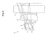
- FIG. 8 shows a FOURTH EXAMPLE of the present invention.
- a cover glass serving as the filter 5 is disposed between the second face 4b of the second lens 4 and the image-taking surface 6.
- the imaging lens 1 of the FOURTH EXAMPLE was set under the following conditions:
- r 3 /d 3 -20.003 was achieved, thereby satisfying the expression (1).
- r 3 /r 2 -7.001 was achieved, thereby satisfying the expression (2).
- r 1 /r 2 0.460 was achieved, thereby satisfying the expression (3).
- f 1 /F 1.026 was achieved, thereby satisfying the expression (4).
- FIG. 9 shows the spherical aberration, astigmatism, and distortion in the imaging lens 1 of the FOURTH EXAMPLE.
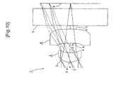
- FIG. 10 shows a FIFTH EXAMPLE of the present invention.
- a cover glass serving as the filter 5 is disposed between the second face 4b of the second lens 4 and the image-taking surface 6.
- the imaging lens 1 of the FIFTH EXAMPLE was set under the following conditions:
- r 3 /d 3 -22.450 was achieved, thereby satisfying the expression (1).
- r 3 /r 2 -11. 000 was achieved, thereby satisfying the expression (2).
- r 1 /r 2 0.522 was achieved, thereby satisfying the expression (3).
- f 1 /F 1.024 was achieved, thereby satisfying the expression (4).
- FIG. 11 shows the spherical aberration, astigmatism, and distortion in the imaging lens 1 of the FIFTH EXAMPLE.
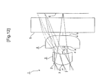
- FIG. 12 shows a SIXTH EXAMPLE of the present invention.
- a cover glass serving as the filter 5 is disposed between the second face 4b of the second lens 4 and the image-taking surface 6.
- the imaging lens 1 of the SIXTH EXAMPLE was set under the following conditions:
- r 3 /d 3 -30.400 was achieved, thereby satisfying the expression (1).
- r 3 /r 2 -11.000 was achieved, thereby satisfying the expression (2).
- r 1 /r 2 0.479 was achieved, thereby satisfying the expression (3).
- f 1 /F 1.003 was achieved, thereby satisfying the expression (4).
- FIG. 13 shows the spherical aberration, astigmatism, and distortion in the imaging lens 1 of the SIXTH EXAMPLE.
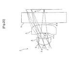
- FIG. 14 shows a SEVENTH EXAMPLE of the present invention.
- a cover glass serving as the filter 5 is disposed between the second face 4b of the second lens 4 and the image-taking surface 6.
- the imaging lens 1 of the SEVENTH EXAMPLE was set under the following conditions:
- r 3 /d 3 -28.000 was achieved, thereby satisfying the expression (1).
- r 3 /r 2 -11. 200 was achieved, thereby satisfying the expression (2).
- r 1 /r 2 0.501 was achieved, thereby satisfying the expression (3).
- f 1 /F 0.992 was achieved, thereby satisfying the expression (4).
- FIG. 15 shows the spherical aberration, astigmatism, and distortion in the imaging lens 1 of the SEVENTH EXAMPLE.
- FIG. 16 shows a EIGHTH EXAMPLE of the present invention.
- a cover glass serving as the filter 5 is disposed between the second face 4b of the second lens 4 and the image-taking surface 6.
- the imaging lens 1 of the EIGHTH EXAMPLE was set under the following conditions:
- r 3 /d 3 -19.100 was achieved, thereby satisfying the expression (1).
- r 3 /r 2 -9.067 was achieved, thereby satisfying the expression (2).
- r 1 /r 2 0.520 was achieved, thereby satisfying the expression (3).
- f 1 /F 0.998 was achieved, thereby satisfying the expression (4).
- FIG. 17 shows the spherical aberration, astigmatism, and distortion in the imaging lens 1 of the EIGHTH EXAMPLE.
- FIG. 18 shows a NINTH EXAMPLE of the present invention.
- a cover glass serving as the filter 5 is disposed between the second face 4b of the second lens 4 and the image-taking surface 6.
- the imaging lens 1 of the NINTH EXAMPLE was set under the following conditions:
- r 3 /d 3 -19.300 was achieved, thereby satisfying the expression (1).
- r 3 /r 2 -9.221 was achieved, thereby satisfying the expression (2).
- r 1 /r 2 0.519 was achieved, thereby satisfying the expression (3).
- f 1 /F 0.989 was achieved, thereby satisfying the expression (4).
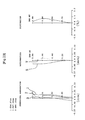
- FIG. 19 shows the spherical aberration, astigmatism, and distortion in the imaging lens 1 of the NINTH EXAMPLE.
- FIG. 20 shows a TENTH EXAMPLE of the present invention.
- a cover glass serving as the filter 5 is disposed between the second face 4b of the second lens 4 and the image-taking surface 6.
- the imaging lens 1 of the NINTH EXAMPLE was set under the following conditions:
- r 3 /d 3 -19.600 was achieved, thereby satisfying the expression (1).
- r 3 /r 2 -9.366 was achieved, thereby satisfying the expression (2).
- r 1 /r 2 0.519 was achieved, thereby satisfying the expression (3).
- f 1 /F 0.989 was achieved, thereby satisfying the expression (4).
- FIG. 21 shows the spherical aberration, astigmatism, and distortion in the imaging lens 1 of the TENTH EXAMPLE.
- FIG. 22 shows an ELEVENTH EXAMPLE of the present invention.
- a cover glass serving as the filter 5 is disposed between the second face 4b of the second lens 4 and the image-taking surface 6.
- the imaging lens 1 of the NINTH EXAMPLE was set under the following conditions:
- FIG. 23 shows the spherical aberration, astigmatism, and distortion in the imaging lens 1 of the ELEVENTH EXAMPLE.
- FIG. 24 shows a TWELFTH EXAMPLE of the present invention.
- a cover glass serving as the filter 5 is disposed between the second face 4b of the second lens 4 and the image-taking surface 6.
- the imaging lens 1 of the NINTH EXAMPLE was set under the following conditions:
- r 3 /d 3 -20.000 was achieved, thereby satisfying the expression (1).
- FIG. 25 shows the spherical aberration, astigmatism, and distortion in the imaging lens 1 of the TWELFTH EXAMPLE.
- a light-transmitting material other than resin material can be suitably used as the material for the first lens and the second lens.
Landscapes
- Physics & Mathematics (AREA)
- General Physics & Mathematics (AREA)
- Optics & Photonics (AREA)
- Lenses (AREA)
Applications Claiming Priority (1)
| Application Number | Priority Date | Filing Date | Title |
|---|---|---|---|
| JP2007307252A JP5090874B2 (ja) | 2007-11-28 | 2007-11-28 | 撮像レンズ |
Publications (1)
| Publication Number | Publication Date |
|---|---|
| EP2065744A1 true EP2065744A1 (fr) | 2009-06-03 |
Family
ID=40379095
Family Applications (1)
| Application Number | Title | Priority Date | Filing Date |
|---|---|---|---|
| EP08105805A Withdrawn EP2065744A1 (fr) | 2007-11-28 | 2008-11-17 | Objectif à deux lentilles |
Country Status (4)
| Country | Link |
|---|---|
| US (1) | US7782553B2 (fr) |
| EP (1) | EP2065744A1 (fr) |
| JP (1) | JP5090874B2 (fr) |
| CN (1) | CN101446680B (fr) |
Cited By (1)
| Publication number | Priority date | Publication date | Assignee | Title |
|---|---|---|---|---|
| US11448858B2 (en) * | 2018-08-08 | 2022-09-20 | Meta Platforms Technologies, Llc | Ultracompact wide field of view lens assembly |
Families Citing this family (5)
| Publication number | Priority date | Publication date | Assignee | Title |
|---|---|---|---|---|
| TW201122716A (en) * | 2009-12-23 | 2011-07-01 | Asia Optical Co Inc | Compact image pickup lens. |
| CN102466862A (zh) * | 2010-11-05 | 2012-05-23 | 亚洲光学股份有限公司 | 微型取像镜头 |
| JPWO2014203675A1 (ja) * | 2013-06-17 | 2017-02-23 | コニカミノルタ株式会社 | 複眼撮像光学系及び複眼撮像装置 |
| CN105572846A (zh) * | 2016-02-19 | 2016-05-11 | 南京昂驰光电科技有限公司 | 一种新型微型光学镜头 |
| CN105549182A (zh) * | 2016-02-19 | 2016-05-04 | 南京昂驰光电科技有限公司 | 一种新型微型光学镜头组 |
Citations (6)
| Publication number | Priority date | Publication date | Assignee | Title |
|---|---|---|---|---|
| JPH04211214A (ja) | 1989-12-28 | 1992-08-03 | Asahi Optical Co Ltd | 撮像レンズ |
| JP2003107344A (ja) | 2000-12-26 | 2003-04-09 | Matsushita Electric Works Ltd | 広角レンズ |
| JP2004062014A (ja) | 2002-07-31 | 2004-02-26 | Milestone Kk | 撮像用レンズ |
| EP1650591A1 (fr) * | 2004-10-19 | 2006-04-26 | Enplas Corporation | Système d'imagerie à deux lentilles positives |
| EP1791012A1 (fr) * | 2005-11-25 | 2007-05-30 | Samsung Electro-Mechanics Co., Ltd. | Système optique très petite |
| EP1887400A1 (fr) * | 2006-08-10 | 2008-02-13 | Enplas Corporation | Lentille d'imagerie à deux lentilles |
Family Cites Families (3)
| Publication number | Priority date | Publication date | Assignee | Title |
|---|---|---|---|---|
| JPH07333494A (ja) * | 1994-06-06 | 1995-12-22 | Konica Corp | 写真撮影用レンズ |
| JP2006337473A (ja) * | 2005-05-31 | 2006-12-14 | Nidec Nissin Corp | 光学装置 |
| JP2009098183A (ja) * | 2007-10-12 | 2009-05-07 | Komatsulite Mfg Co Ltd | 撮像レンズ |
-
2007
- 2007-11-28 JP JP2007307252A patent/JP5090874B2/ja not_active Expired - Fee Related
-
2008
- 2008-11-17 EP EP08105805A patent/EP2065744A1/fr not_active Withdrawn
- 2008-11-25 US US12/315,171 patent/US7782553B2/en not_active Expired - Fee Related
- 2008-11-27 CN CN2008101815555A patent/CN101446680B/zh not_active Expired - Fee Related
Patent Citations (6)
| Publication number | Priority date | Publication date | Assignee | Title |
|---|---|---|---|---|
| JPH04211214A (ja) | 1989-12-28 | 1992-08-03 | Asahi Optical Co Ltd | 撮像レンズ |
| JP2003107344A (ja) | 2000-12-26 | 2003-04-09 | Matsushita Electric Works Ltd | 広角レンズ |
| JP2004062014A (ja) | 2002-07-31 | 2004-02-26 | Milestone Kk | 撮像用レンズ |
| EP1650591A1 (fr) * | 2004-10-19 | 2006-04-26 | Enplas Corporation | Système d'imagerie à deux lentilles positives |
| EP1791012A1 (fr) * | 2005-11-25 | 2007-05-30 | Samsung Electro-Mechanics Co., Ltd. | Système optique très petite |
| EP1887400A1 (fr) * | 2006-08-10 | 2008-02-13 | Enplas Corporation | Lentille d'imagerie à deux lentilles |
Cited By (1)
| Publication number | Priority date | Publication date | Assignee | Title |
|---|---|---|---|---|
| US11448858B2 (en) * | 2018-08-08 | 2022-09-20 | Meta Platforms Technologies, Llc | Ultracompact wide field of view lens assembly |
Also Published As
| Publication number | Publication date |
|---|---|
| CN101446680B (zh) | 2012-07-04 |
| US7782553B2 (en) | 2010-08-24 |
| JP2009128883A (ja) | 2009-06-11 |
| JP5090874B2 (ja) | 2012-12-05 |
| US20090135504A1 (en) | 2009-05-28 |
| CN101446680A (zh) | 2009-06-03 |
Similar Documents
| Publication | Publication Date | Title |
|---|---|---|
| EP3961281B1 (fr) | Ensemble lentille d'image optique, unité de capture d'image et dispositif électronique | |
| US7359127B2 (en) | Imaging lens | |
| EP2860564B1 (fr) | Module de lentille | |
| US7821724B2 (en) | Photographing optical lens assembly | |
| EP1348990B1 (fr) | Objectif composé de trois lentilles | |
| US7196856B2 (en) | Imaging lens system | |
| US9897777B2 (en) | Optical system | |
| US20160313538A1 (en) | Photographic Lens System Enabling Reduction in Tightness of Manufacturing Tolerance | |
| US7450323B2 (en) | Imaging lens and imaging device including the imaging lens | |
| EP2336815A1 (fr) | Objectif rétrofocus à quatre lentilles et appareil d'imagerie | |
| US8289624B2 (en) | Imaging lens system | |
| EP1995620A1 (fr) | Objectif d'imagerie | |
| EP4137858B1 (fr) | Lentille d'imagerie optique | |
| US20060126193A1 (en) | Lens assembly for an image sensor background of the invention | |
| KR20150135919A (ko) | 줌렌즈계 | |
| KR101215826B1 (ko) | 촬영 렌즈 광학계 | |
| EP2065744A1 (fr) | Objectif à deux lentilles | |
| JPH10325919A (ja) | 結像レンズ | |
| US6987625B2 (en) | Imaging lens system | |
| EP1650592B1 (fr) | Objectif compact à deux lentilles | |
| EP1777568B1 (fr) | Objectif compact ayant trois lentilles simples | |
| EP1965238A1 (fr) | Lentille d'imagerie et dispositif d'imagerie l'incluant | |
| JP3595308B2 (ja) | 撮像レンズ | |
| EP4099074B1 (fr) | Lentille d'imagerie optique | |
| EP1914581A1 (fr) | Objectif compact du type téléobjectif et ayant trois lentilles minces |
Legal Events
| Date | Code | Title | Description |
|---|---|---|---|
| PUAI | Public reference made under article 153(3) epc to a published international application that has entered the european phase |
Free format text: ORIGINAL CODE: 0009012 |
|
| AK | Designated contracting states |
Kind code of ref document: A1 Designated state(s): AT BE BG CH CY CZ DE DK EE ES FI FR GB GR HR HU IE IS IT LI LT LU LV MC MT NL NO PL PT RO SE SI SK TR |
|
| AX | Request for extension of the european patent |
Extension state: AL BA MK RS |
|
| AKX | Designation fees paid | ||
| REG | Reference to a national code |
Ref country code: DE Ref legal event code: 8566 |
|
| STAA | Information on the status of an ep patent application or granted ep patent |
Free format text: STATUS: THE APPLICATION IS DEEMED TO BE WITHDRAWN |
|
| 18D | Application deemed to be withdrawn |
Effective date: 20091204 |