EP2065963B1 - Système de batterie refroidi via un agent de refroidissement - Google Patents
Système de batterie refroidi via un agent de refroidissement Download PDFInfo
- Publication number
- EP2065963B1 EP2065963B1 EP20080020759 EP08020759A EP2065963B1 EP 2065963 B1 EP2065963 B1 EP 2065963B1 EP 20080020759 EP20080020759 EP 20080020759 EP 08020759 A EP08020759 A EP 08020759A EP 2065963 B1 EP2065963 B1 EP 2065963B1
- Authority
- EP
- European Patent Office
- Prior art keywords
- cooling
- battery
- plate
- battery system
- cited
- Prior art date
- Legal status (The legal status is an assumption and is not a legal conclusion. Google has not performed a legal analysis and makes no representation as to the accuracy of the status listed.)
- Not-in-force
Links
Images

Classifications
-
- H—ELECTRICITY
- H01—ELECTRIC ELEMENTS
- H01M—PROCESSES OR MEANS, e.g. BATTERIES, FOR THE DIRECT CONVERSION OF CHEMICAL ENERGY INTO ELECTRICAL ENERGY
- H01M10/00—Secondary cells; Manufacture thereof
- H01M10/05—Accumulators with non-aqueous electrolyte
- H01M10/052—Li-accumulators
-
- H—ELECTRICITY
- H01—ELECTRIC ELEMENTS
- H01M—PROCESSES OR MEANS, e.g. BATTERIES, FOR THE DIRECT CONVERSION OF CHEMICAL ENERGY INTO ELECTRICAL ENERGY
- H01M10/00—Secondary cells; Manufacture thereof
- H01M10/34—Gastight accumulators
- H01M10/345—Gastight metal hydride accumulators
-
- H—ELECTRICITY
- H01—ELECTRIC ELEMENTS
- H01M—PROCESSES OR MEANS, e.g. BATTERIES, FOR THE DIRECT CONVERSION OF CHEMICAL ENERGY INTO ELECTRICAL ENERGY
- H01M10/00—Secondary cells; Manufacture thereof
- H01M10/60—Heating or cooling; Temperature control
- H01M10/61—Types of temperature control
- H01M10/613—Cooling or keeping cold
-
- H—ELECTRICITY
- H01—ELECTRIC ELEMENTS
- H01M—PROCESSES OR MEANS, e.g. BATTERIES, FOR THE DIRECT CONVERSION OF CHEMICAL ENERGY INTO ELECTRICAL ENERGY
- H01M10/00—Secondary cells; Manufacture thereof
- H01M10/60—Heating or cooling; Temperature control
- H01M10/62—Heating or cooling; Temperature control specially adapted for specific applications
- H01M10/625—Vehicles
-
- H—ELECTRICITY
- H01—ELECTRIC ELEMENTS
- H01M—PROCESSES OR MEANS, e.g. BATTERIES, FOR THE DIRECT CONVERSION OF CHEMICAL ENERGY INTO ELECTRICAL ENERGY
- H01M10/00—Secondary cells; Manufacture thereof
- H01M10/60—Heating or cooling; Temperature control
- H01M10/64—Heating or cooling; Temperature control characterised by the shape of the cells
- H01M10/647—Prismatic or flat cells, e.g. pouch cells
-
- H—ELECTRICITY
- H01—ELECTRIC ELEMENTS
- H01M—PROCESSES OR MEANS, e.g. BATTERIES, FOR THE DIRECT CONVERSION OF CHEMICAL ENERGY INTO ELECTRICAL ENERGY
- H01M10/00—Secondary cells; Manufacture thereof
- H01M10/60—Heating or cooling; Temperature control
- H01M10/65—Means for temperature control structurally associated with the cells
- H01M10/655—Solid structures for heat exchange or heat conduction
- H01M10/6554—Rods or plates
- H01M10/6555—Rods or plates arranged between the cells
-
- H—ELECTRICITY
- H01—ELECTRIC ELEMENTS
- H01M—PROCESSES OR MEANS, e.g. BATTERIES, FOR THE DIRECT CONVERSION OF CHEMICAL ENERGY INTO ELECTRICAL ENERGY
- H01M10/00—Secondary cells; Manufacture thereof
- H01M10/60—Heating or cooling; Temperature control
- H01M10/65—Means for temperature control structurally associated with the cells
- H01M10/655—Solid structures for heat exchange or heat conduction
- H01M10/6556—Solid parts with flow channel passages or pipes for heat exchange
-
- H—ELECTRICITY
- H01—ELECTRIC ELEMENTS
- H01M—PROCESSES OR MEANS, e.g. BATTERIES, FOR THE DIRECT CONVERSION OF CHEMICAL ENERGY INTO ELECTRICAL ENERGY
- H01M10/00—Secondary cells; Manufacture thereof
- H01M10/60—Heating or cooling; Temperature control
- H01M10/65—Means for temperature control structurally associated with the cells
- H01M10/656—Means for temperature control structurally associated with the cells characterised by the type of heat-exchange fluid
- H01M10/6561—Gases
- H01M10/6562—Gases with free flow by convection only
-
- H—ELECTRICITY
- H01—ELECTRIC ELEMENTS
- H01M—PROCESSES OR MEANS, e.g. BATTERIES, FOR THE DIRECT CONVERSION OF CHEMICAL ENERGY INTO ELECTRICAL ENERGY
- H01M10/00—Secondary cells; Manufacture thereof
- H01M10/60—Heating or cooling; Temperature control
- H01M10/65—Means for temperature control structurally associated with the cells
- H01M10/656—Means for temperature control structurally associated with the cells characterised by the type of heat-exchange fluid
- H01M10/6567—Liquids
- H01M10/6568—Liquids characterised by flow circuits, e.g. loops, located externally to the cells or cell casings
-
- H—ELECTRICITY
- H01—ELECTRIC ELEMENTS
- H01M—PROCESSES OR MEANS, e.g. BATTERIES, FOR THE DIRECT CONVERSION OF CHEMICAL ENERGY INTO ELECTRICAL ENERGY
- H01M50/00—Constructional details or processes of manufacture of the non-active parts of electrochemical cells other than fuel cells, e.g. hybrid cells
- H01M50/10—Primary casings; Jackets or wrappings
- H01M50/102—Primary casings; Jackets or wrappings characterised by their shape or physical structure
- H01M50/103—Primary casings; Jackets or wrappings characterised by their shape or physical structure prismatic or rectangular
-
- H—ELECTRICITY
- H01—ELECTRIC ELEMENTS
- H01M—PROCESSES OR MEANS, e.g. BATTERIES, FOR THE DIRECT CONVERSION OF CHEMICAL ENERGY INTO ELECTRICAL ENERGY
- H01M50/00—Constructional details or processes of manufacture of the non-active parts of electrochemical cells other than fuel cells, e.g. hybrid cells
- H01M50/10—Primary casings; Jackets or wrappings
- H01M50/116—Primary casings; Jackets or wrappings characterised by the material
- H01M50/117—Inorganic material
- H01M50/119—Metals
-
- H—ELECTRICITY
- H01—ELECTRIC ELEMENTS
- H01M—PROCESSES OR MEANS, e.g. BATTERIES, FOR THE DIRECT CONVERSION OF CHEMICAL ENERGY INTO ELECTRICAL ENERGY
- H01M50/00—Constructional details or processes of manufacture of the non-active parts of electrochemical cells other than fuel cells, e.g. hybrid cells
- H01M50/20—Mountings; Secondary casings or frames; Racks, modules or packs; Suspension devices; Shock absorbers; Transport or carrying devices; Holders
- H01M50/204—Racks, modules or packs for multiple batteries or multiple cells
- H01M50/207—Racks, modules or packs for multiple batteries or multiple cells characterised by their shape
- H01M50/209—Racks, modules or packs for multiple batteries or multiple cells characterised by their shape adapted for prismatic or rectangular cells
-
- H—ELECTRICITY
- H01—ELECTRIC ELEMENTS
- H01M—PROCESSES OR MEANS, e.g. BATTERIES, FOR THE DIRECT CONVERSION OF CHEMICAL ENERGY INTO ELECTRICAL ENERGY
- H01M50/00—Constructional details or processes of manufacture of the non-active parts of electrochemical cells other than fuel cells, e.g. hybrid cells
- H01M50/20—Mountings; Secondary casings or frames; Racks, modules or packs; Suspension devices; Shock absorbers; Transport or carrying devices; Holders
- H01M50/233—Mountings; Secondary casings or frames; Racks, modules or packs; Suspension devices; Shock absorbers; Transport or carrying devices; Holders characterised by physical properties of casings or racks, e.g. dimensions
- H01M50/24—Mountings; Secondary casings or frames; Racks, modules or packs; Suspension devices; Shock absorbers; Transport or carrying devices; Holders characterised by physical properties of casings or racks, e.g. dimensions adapted for protecting batteries from their environment, e.g. from corrosion
-
- H—ELECTRICITY
- H01—ELECTRIC ELEMENTS
- H01M—PROCESSES OR MEANS, e.g. BATTERIES, FOR THE DIRECT CONVERSION OF CHEMICAL ENERGY INTO ELECTRICAL ENERGY
- H01M50/00—Constructional details or processes of manufacture of the non-active parts of electrochemical cells other than fuel cells, e.g. hybrid cells
- H01M50/20—Mountings; Secondary casings or frames; Racks, modules or packs; Suspension devices; Shock absorbers; Transport or carrying devices; Holders
- H01M50/289—Mountings; Secondary casings or frames; Racks, modules or packs; Suspension devices; Shock absorbers; Transport or carrying devices; Holders characterised by spacing elements or positioning means within frames, racks or packs
- H01M50/291—Mountings; Secondary casings or frames; Racks, modules or packs; Suspension devices; Shock absorbers; Transport or carrying devices; Holders characterised by spacing elements or positioning means within frames, racks or packs characterised by their shape
-
- H—ELECTRICITY
- H01—ELECTRIC ELEMENTS
- H01M—PROCESSES OR MEANS, e.g. BATTERIES, FOR THE DIRECT CONVERSION OF CHEMICAL ENERGY INTO ELECTRICAL ENERGY
- H01M50/00—Constructional details or processes of manufacture of the non-active parts of electrochemical cells other than fuel cells, e.g. hybrid cells
- H01M50/20—Mountings; Secondary casings or frames; Racks, modules or packs; Suspension devices; Shock absorbers; Transport or carrying devices; Holders
- H01M50/289—Mountings; Secondary casings or frames; Racks, modules or packs; Suspension devices; Shock absorbers; Transport or carrying devices; Holders characterised by spacing elements or positioning means within frames, racks or packs
- H01M50/293—Mountings; Secondary casings or frames; Racks, modules or packs; Suspension devices; Shock absorbers; Transport or carrying devices; Holders characterised by spacing elements or positioning means within frames, racks or packs characterised by the material
-
- H—ELECTRICITY
- H01—ELECTRIC ELEMENTS
- H01M—PROCESSES OR MEANS, e.g. BATTERIES, FOR THE DIRECT CONVERSION OF CHEMICAL ENERGY INTO ELECTRICAL ENERGY
- H01M10/00—Secondary cells; Manufacture thereof
- H01M10/60—Heating or cooling; Temperature control
- H01M10/65—Means for temperature control structurally associated with the cells
- H01M10/656—Means for temperature control structurally associated with the cells characterised by the type of heat-exchange fluid
- H01M10/6569—Fluids undergoing a liquid-gas phase change or transition, e.g. evaporation or condensation
-
- Y—GENERAL TAGGING OF NEW TECHNOLOGICAL DEVELOPMENTS; GENERAL TAGGING OF CROSS-SECTIONAL TECHNOLOGIES SPANNING OVER SEVERAL SECTIONS OF THE IPC; TECHNICAL SUBJECTS COVERED BY FORMER USPC CROSS-REFERENCE ART COLLECTIONS [XRACs] AND DIGESTS
- Y02—TECHNOLOGIES OR APPLICATIONS FOR MITIGATION OR ADAPTATION AGAINST CLIMATE CHANGE
- Y02E—REDUCTION OF GREENHOUSE GAS [GHG] EMISSIONS, RELATED TO ENERGY GENERATION, TRANSMISSION OR DISTRIBUTION
- Y02E60/00—Enabling technologies; Technologies with a potential or indirect contribution to GHG emissions mitigation
- Y02E60/10—Energy storage using batteries
-
- Y—GENERAL TAGGING OF NEW TECHNOLOGICAL DEVELOPMENTS; GENERAL TAGGING OF CROSS-SECTIONAL TECHNOLOGIES SPANNING OVER SEVERAL SECTIONS OF THE IPC; TECHNICAL SUBJECTS COVERED BY FORMER USPC CROSS-REFERENCE ART COLLECTIONS [XRACs] AND DIGESTS
- Y02—TECHNOLOGIES OR APPLICATIONS FOR MITIGATION OR ADAPTATION AGAINST CLIMATE CHANGE
- Y02T—CLIMATE CHANGE MITIGATION TECHNOLOGIES RELATED TO TRANSPORTATION
- Y02T10/00—Road transport of goods or passengers
- Y02T10/60—Other road transportation technologies with climate change mitigation effect
- Y02T10/70—Energy storage systems for electromobility, e.g. batteries
Definitions
- the present invention relates to a battery system having a battery block with a plurality of stacked rectangular batteries joined together and cooled via a coolant, and in particular relates to a battery system best suited as a power source for automobile applications such as in a hybrid car.
- a battery system provided with many rectangular batteries can produce higher output voltages and charge and discharge with high currents.
- a battery system used as a power source unit for an automobile is discharged at high currents during vehicle acceleration and is charged with high currents under conditions such as regenerative braking.
- forced cooling is implemented via air or coolant. Because of the low heat capacity of air, it is difficult to rapidly air-cool batteries generating considerable amounts of heat. Further, if the amount of ventilation is increased to increase forced air-cooling, it has the additional drawback that noise levels increase.
- a forced air-cooling system also has the detrimental effect that dust included in the air deposits inside the system to reduce cooling efficiency over time.
- Document JP 07006796 describes a battery case in which side walls are stood along the peripheral edge of a bottom plate and plural partitioning plates are provided in parallel with each other inside thereof to house batteries.
- a cap plate is provided in the upper part of the battery case, and a coolant pipeline is embedded in the bottom plate and the partitioning plates.
- the cooling medium is flowed in this coolant pipeline to cool the multiple batteries through the bottom of the battery, which contacts with the bottom plate, and the side wall of the battery, which contacts with the partitioning plates. Since a wide cooling area can be obtained, the necessary and the sufficient cooling is performed.
- Document WO 03/015192 A2 describes a thermal jacket adapted to accommodate and cool a storage battery placed in the engine compartment of an automobile and exposed to heat at elevated temperatures emanating from the engine.
- the walls of the rectangular jacket are formed of rigid, foam-plastic material which thermally isolate the battery from the engine.
- cooling pipe is disposed between stacked rectangular batteries. Cooling pipe is chilled by the supply of cooling water to in-turn cool the rectangular batteries. Although this system can efficiently cool rectangular batteries with cooling water, it requires a network of cooling pipe disposed between rectangular batteries. Arrangement of cooling pipe in a battery system having many stacked rectangular batteries is extremely complicated.
- the first object of the present invention addresses this drawback.
- the first object is to provide a battery system that can efficiently cool rectangular batteries via cooling pipe, which can be installed easily.
- Japanese Patent Application Disclosure HEI2-79567 (1990 ) cites a simpler structure that can cool a plurality of batteries.
- This disclosure describes a battery system having a battery block disposed on top of a cooling plate, and the batteries are cooled via that cooling plate.
- the cooling plate is chilled to cool a plurality of batteries.
- the cooling plate can be a thick metal plate provided with coolant passageways traversing in the horizontal direction. Coolant can be supplied to those passageways for cooling.
- the cooling plate can be a thick metal plate provided with coolant passageways traversing in the horizontal direction. Coolant can be supplied to those passageways for cooling.
- there is large thermal resistance between the coolant and the batteries there is large thermal resistance between the coolant and the batteries, and rapid, efficient battery cooling is difficult to attain. Battery temperature rise is detected, and the cooling plate is chilled.
- the second object of the present invention addresses these drawbacks.
- the second object is to provide a battery system that can rapidly and efficiently cool batteries via coolant while effectively preventing thermal efficiency reduction due to transfer of external heat to the coolant.
- the battery system of claim 1 in particular has a battery block 3, 33 with a plurality of rectangular batteries 1, 31 retained in a stacked configuration by a battery holder 4, 34; a cooling plate 8, 38 disposed in thermal contact with the bottom surface of the battery block 3, 33 and having a hollow region 18, 48 inside; cooling pipe 6, 36 disposed inside the hollow region 18, 48 of the cooling plate 8, 38; and a coolant supply device 7, 37 to supply coolant to the cooling pipe 6, 36.
- the hollow cooling plate 8, 38 has a surface plate 8A, 38A that makes thermal contact with the bottom surface of the battery block 3, 33. Cooling pipe 6, 36 is disposed within the hollow region 18, 38 in contact with the inside of the surface plate 8A, 38A. Finally, the cooling plate 8, 38 hollow region 18, 48 is filled with plastic foam 9.
- the battery system above has the characteristic that rectangular batteries can be efficiently cooled with cooling pipe that can be arranged in simple fashion.
- cooling pipe that can be arranged in simple fashion.
- rectangular batteries can be cooled quietly and efficiently with a simple structure. This is because the battery system above has cooling pipe disposed beneath the battery block and coolant is used to cool the rectangular batteries.
- the battery system above has the characteristic that batteries can be rapidly and efficiently cooled via coolant while effectively preventing thermal efficiency reduction due to absorption of external heat by the coolant.
- the battery system above is provided with a hollow region in the battery cooling plate, cooling pipe is disposed in that hollow region, and a surface plate is provided on the cooling plate for thermal contact with the bottom surface of the battery block.
- Cooling pipe is disposed in contact with the inside of the surface plate and the hollow region of the cooling plate is filled with plastic foam.
- plastic foam filling the hollow region presses the cooling pipe against the surface plate.
- cooling pipe makes intimate contact with the surface plate for ideal thermal connection. Therefore, cooling pipe chilled by coolant can efficiently cool the surface plate, and the surface plate can efficiently cool the batteries.
- plastic foam filling the hollow region supports and reinforces the surface plate from the inside. This dampens any resonant vibration of the surface plate, and gives the cooling plate a robust structure to support the weight of the heavy battery block loaded on top.
- urethane foam can be used as the plastic foam 9 for filling the hollow region 18, 48 of the cooling plate 8, 38. Further, urethane foam, which is injected into the hollow region 18, 48, and which turns to foam and hardens inside the hollow region 18, 48, can be used as the plastic foam 9 in the cooling plate 8, 38 of the battery system of the present invention.
- self-foaming plastic foam 9 can be used to fill the hollow region 18, 48 of the cooling plate 8, 38.
- the thermal insulating properties of the plastic foam can be improved by using self-foaming plastic foam. Therefore, cooling pipe can be thermally insulated in an ideal fashion, and external heat absorption and reduced thermal efficiency can be prevented.
- cooling pipe 6, 36 can be configured with a cross-sectional shape having a flat section 6a, 36a, and this flat section 6a, 36a can be put in contact with the surface plate 8A, 38A.
- the contact area between the cooling pipe and the surface plate is increased, and the cooling pipe and surface plate can be thermally joined in a preferable arrangement. Furthermore, the cooling plate hollow region is filled with plastic foam while cooling pipe flat sections are in close contact with the surface plate. Close contact between the cooling pipe and surface plate can be made even more reliable due to the plastic foam.
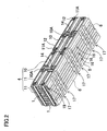
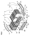
- Fig. 1 is an abbreviated structural diagram of a battery system for one embodiment of the present invention
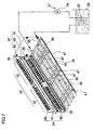
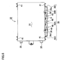
- Figs. 1-6 show a first embodiment and Figs. 7 and 8 show a second embodiment of the present invention.
- the battery system shown in these figures is most suitable as a power source primarily for an electrically powered vehicle such as a hybrid car, which is driven by both an engine and an electric motor, or an electric automobile, which is driven by only an electric motor.
- an electrically powered vehicle such as a hybrid car, which is driven by both an engine and an electric motor, or an electric automobile, which is driven by only an electric motor.
- the present invention can be used in vehicles other than a hybrid car or electric automobile, and it can also be used in applications that require large output other than electrically powered vehicles.
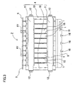
- the battery systems of the following embodiments are provided with a battery block 3, 33 having a plurality of rectangular batteries 1, 31 that are wider than they are thick connected in a stacked configuration by a battery holder 4, 34; a cooling plate 8, 38 disposed in thermal contact with the bottom surface of the battery block 3, 33 and having a hollow region 18, 48 inside; cooling pipe 6, 36 disposed inside the hollow region 18, 48 of the cooling plate 8, 38; and a coolant supply device 7, 37 to supply coolant to the cooling pipe 6, 36.
- rectangular batteries 1 are assembled as four rows of battery units 2, which are retained by the battery holder 4.
- the four rows of battery units 2 each have the same number of rectangular batteries 1 stacked together. Since the battery block 3 of the figures has ten rectangular batteries 1 stacked in each battery unit 2, it is provided with a total of forty rectangular batteries 1.
- the battery block 3 is provided with ducts 14 for cooling gas ventilation between the four rows of battery units 2.
- the rectangular batteries 1 of the four battery units 2 are retained in parallel orientation by the battery holder 4.
- a rectangular battery 1 in one battery unit 2, which is opposite a rectangular battery 1 in an adjacent battery unit 2, lies in the same plane as its counterpart in the adjacent battery unit 2.
- the battery holder there is no requirement for the battery holder to hold four rows of battery units.
- rectangular batteries can also be arranged in battery units of three rows or less, or five rows or more.
- the battery block 3 has cooling spacers 15 sandwiched between the stacked rectangular batteries 1.
- the cooling spacers 15 are made of metal plate with superior thermal conductivity such as aluminum or copper.
- the surfaces of the rectangular batteries 1 are electrically insulated from intervening cooling spacers 15 by insulating material (not illustrated). Rectangular batteries 1 with electrically insulated surfaces can have external cases made of metal such as aluminum. Sandwiching cooling spacers 15, also made of metal, between those rectangular batteries 1 allows efficient and uniform cooling.
- An external battery case made of metal has superior thermal conduction, and allows the entire battery to efficiently attain a uniform temperature.
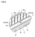
- a cooling spacer 15 has a vertical section 15A that makes thermal contact on both sides with adjacent rectangular battery 1 surfaces.
- a horizontal section 15B that makes thermal contact with the cooling plate 8 is established at the base of the vertical section 15A.
- the vertical section 15A of the cooling spacer 15 is shaped to mate with rectangular batteries 1 on both sides and align in a fixed location. As a result, rectangular batteries 1 and cooling spacers 15 can be stacked without shifting out of position.
- the bottom surface of the horizontal section 15B makes close contact with the surface plate 8A of the cooling plate 8 to enable efficient cooling by the cooling plate 8. In a battery system having this type of cooling spacers 15 sandwiched between rectangular batteries 1, rectangular batteries 1 can be efficiently cooled by the cooling spacers 15.
- Both sides of the vertical sections 15A of the cooling spacers 15 of the figures are provided with a plurality of cooling channels 15a for forced cooling by a cooling gas.
- a cooling spacer 15 of this configuration is cooled by the cooling plate 8 and can also be cooled by cooling gas forced to pass through the cooling channels 15a.
- the battery system of Fig. 1 is provided with ducts 14 between battery units 2. Cooling gas is forced to pass through these ducts 14 and to pass through the cooling channels 15a of the cooling spacers 15.
- cooling spacers which are cooled by thermal contact with the cooling plate, do not necessarily have to be cooled by a cooling gas. Consequently, cooling spacer vertical sections do not necessarily need cooling channels.
- a battery system provided with cooling spacers 15 between rectangular batteries 1 can efficiently cool the rectangular batteries 1 via the cooling spacers 15.
- cooling spacers do not necessarily have to be provided between the rectangular batteries. This is because the bottom surfaces of the rectangular batteries are cooled by the cooling plate.
- electrically insulating spacers can be sandwiched between rectangular batteries. In this type of battery system, adjacent rectangular batteries are electrically insulated by insulating material. Insulating spacers can also be provided with cooling channels for cooling by a cooling gas.
- a rectangular battery 1 is wider than it is thick or thinner than it is wide. Rectangular batteries 1 are stacked in the direction of their thin side to form a battery block 3. These rectangular batteries 1 are lithium ion rechargeable batteries. However, the rectangular batteries can also be other rechargeable batteries such as nickel hydride or nickel cadmium batteries.
- the rectangular batteries 1 of the figures have wide rectangular surfaces on both sides, and those wide surfaces are stacked opposite one-another to form a battery block 3.
- the upper surface of a rectangular battery 1 is provided with positive and negative electrode terminals 5 projecting upward at both ends, and a safety valve opening 1A is provided at the center of the upper surface.
- Each rectangular battery of the figures has its positive and negative electrode terminals 5 bent in opposite directions, and adjacent rectangular batteries 1 have their positive and negative electrode terminals 5 opposite each other and bent in opposite directions.
- positive and negative electrode terminals 5 of adjacent rectangular batteries 1 are joined with the batteries in a stacked configuration to connect the batteries in series.
- electrode terminals joined in the stacked configuration are connected by fasteners such as nuts and bolts.
- the positive and negative electrode terminals of the rectangular batteries can also be connected in series via bus bars.
- a battery system with adjacent rectangular batteries connected in series can increase output voltage to enable large output.
- the battery system can also have adjacent rectangular batteries connected in parallel.
- a battery block 3 has stacked rectangular batteries 1 held in a battery holder 4.
- a battery block 3 of the figures has two rows of battery units 2 held in a battery holder 4.
- a battery holder 4 sandwiches two rows of battery units 2 within a pair of retaining plates 10.
- the retaining plates 10 are held together by connecting rails 11.
- the battery block 3 has retaining plates 10 disposed at both ends, the pair of retaining plates 10 are connected by connecting rails 11, and the stacked rectangular batteries 1 are held in the stacked configuration by the battery holder 4.
- a retaining plate 10 has a rectangular outline with approximately the same shape as two side-by-side rectangular batteries 1.
- a through-hole 10A is provided in the center region to open the retaining plate 10 for the duct established between adjacent battery units 2.
- An inward right-angle bend 11A is provided at both ends of each connecting rail 11 for attachment to the retaining plates 10 via screws 12.
- the retaining plates 10 of the figures are provided with connecting, holes 10B to attach the right-angle bends 11A of the connecting rails 11.
- Each retaining plate 10 has four connecting holes 10B established at its four corners.
- Connecting holes 10B are formed to accept and mate with screws 12.
- Connecting rails 11 can be attached to the retaining plates 10 by screwing screws 12 through holes in the right-angle bends 11A into connecting holes 10B in the retaining plates 10.
- the cooling plate 8 is disposed in thermal contact with the bottom surface of the battery block 3 to cool battery block 3 rectangular batteries 1 from below.
- a cooling plate 8 is disposed only under the bottom surface of the battery block 3 to cool it from below.
- cooling can be implemented by a cooling plate disposed at the upper surface or side surface of the battery block in addition to the bottom surface.
- Figs 7 and 8 show a battery system with rectangular batteries 31 rotated onto their side to orient the positive and negative electrode terminal 35 surface as a side surface. Since rectangular battery 31 side surfaces become upper surfaces in this orientation, cooling plates 38 can be disposed at both the upper and lower surfaces to efficiently cool the rectangular batteries 31.
- rectangular batteries 31 are rotated onto their side and stacked in that orientation to form a battery unit 32.
- Two battery units 32 are joined in a straight line to form a single row battery block 33.
- Each battery unit 32 has a plurality of stacked rectangular batteries 31 held in place by a battery holder 34.
- the battery holder is made up of a pair of retaining plates 40 that sandwich the stacked rectangular batteries 31, and connecting rails 41 that join the retaining plates 40.
- Electrically insulating spacers (not illustrated) are sandwiched between rectangular batteries 31 of a battery unit 32, and adjacent rectangular batteries 31 are insulated by those insulating spacers.
- a cooling plate 38 is disposed under the bottom surface of the battery block 33 to cool the rectangular batteries 31.
- the cooling plate 38 of the figures is positioned at the bottom surface of the battery block 33, and makes direct contact and thermal connection with side surfaces of the rectangular batteries 31.
- the cooling plate 38 can make direct contact with rectangular battery 31 surfaces for efficient cooling.
- the battery system can also have cooling spacers sandwiched between rectangular batteries. These cooling spacers can make thermal contact with the surfaces of adjacent rectangular batteries on both sides to cool the batteries.
- a cooling spacer can be, for example, a spacer having a vertical section disposed between adjacent rectangular batteries and a horizontal section at the base of the vertical section for thermal contact with the cooling plate.
- cooling spacer In this cooling spacer, adjacent rectangular batteries are retained in fixed positions by the vertical section while the bottom surface of the horizontal section makes close contact with the cooling plate to allow effective cooling by the cooling plate.
- cooling spacers can be provided with a plurality of cooling channels, and rectangular batteries can be cooled by forced passage of cooling gas through those cooling channels.
- the cooling plate 8, 38 and rectangular batteries 1, 31 are thermally connected in an electrically insulated fashion.
- the external cases of rectangular batteries 1, 31 are covered with insulating material (not illustrated). Electrical insulation of rectangular batteries from the cooling plate can also be implemented by a configuration that covers the surface of the cooling plate opposite rectangular battery surfaces with insulating material.
- rectangular battery external cases are not insulated, adjacent rectangular batteries are insulated by insulating separators, and rectangular batteries are insulated from the cooling plate by insulating material provided on the surface of the cooling plate.
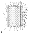
- the cooling plate 8, 38 has a box-shape with a hollow region 18, 48 inside.
- the cooling plate 8, 38 has a surface plate 8A, 38A on top that makes thermal contact with the bottom surface of the battery block 3, 33.
- a bottom plate 8B, 38B is provided beneath the surface plate 8A, 38A.
- the surface plate 8A, 38A and bottom plate 8B, 38B have the same outline shape and are joined around the perimeter by side-walls 8C, 38C to form an enclosure that establishes the hollow region 18, 48.
- the cooling plate 8, 38 of the figures has its bottom plate 8B, 38B and side-walls 8C, 38C connected in a single-piece fashion.
- the surface plate 8A, 38A, the bottom plate 8B, 38B, and the side-walls 8C, 38C are made of metal plate.
- the surface plate 8A, 38A is made of metal plate having high thermal conductivity such as aluminum or copper. Since superior thermal conductivity characteristics are not required for the bottom plate 8B, 38B and side-walls 8C, 38C, they do not need to be made from metal plate and they can be made of plate material having low thermal conductivity such as plastic.
- Cooling pipe 6, 36 is arranged inside the hollow region 18, 48 of the cooling plate 8, 38. Cooling pipe 6, 36 is made of high thermal conductivity metal such as aluminum or copper. Cooling pipe 6, 36 is disposed in contact with the inside of the surface plate 8A, 38A, and specifically, is disposed in thermal contact with the surface plate 8A, 38A. In a battery system having both the surface plate 8A, 38A and cooling pipe 6, 36 made of thin high thermal conductivity aluminum or copper, rectangular batteries 1, 31 can be efficiently cooled via a coolant. Cooling pipe 6, 36 shown in the cross-section views of Figs.
- cooling pipe 6, 36 is disposed in contact with, and thermally connected with the surface plate 8A, 38A, and also separated from the bottom plate 8B, 38B.
- the bottom plate 8B, 38B is not directly cooled by the cooling pipe 6, 36. Therefore, cooling pipe 6, 36 efficiently cools the surface plate 8A, 38A.
- the bottom plate 8B, 38B of the figures is provided with a plurality of lengthwise grooves 16, 46 and lateral grooves 17, 47. Fabrication of lengthwise and laterally extending grooves in the bottom plate 8B, 38B improves bending strength.
- the hollow region 18, 48 of the cooling plate 8, 38 is filled with plastic foam 9. Except for the interior of the cooling pipe 6, 36, the entire hollow region 18, 48 is filled with plastic foam 9. In addition to thermally insulating the cooling pipe 6, 36, the plastic foam 9 also stabilizes the thermal connection between the cooling pipe 6, 36 and the surface plate 8A, 38A.
- This plastic foam 9 is injected into the hollow region 18, 48 with the cooling pipe 6, 36 in place, and hardens in a foam state. Unhardened plastic is injected into the hollow region 18, 48 through an injection hole 19, 49 at the bottom of the hollow region 18, 48. Unhardened plastic injected into the bottom of the hollow region 18, 48 is in the form of a paste or liquid. The injected plastic turns to foam and expands to fill the hollow region 18, 48.
- the cooling plate 8 shown in Figs. 1-4 has both ends of the cooling pipe 6 disposed inside the hollow region 18 pulled-out one end of the cooling plate 8. These pulled-out sections are bent upwards to establish coolant plumbing access points 6Y. Cooling pipe 6 is connected to a coolant supply device 7 via these plumbing access points 6Y.
- a coolant supply device 7, 37 supplies coolant to the cooling pipe. Coolant that chills the cooling pipe by the heat of vaporization, and cooled liquid such as water or oil that cools the cooling pipe are both used.
- a coolant supply device 7 that supplies coolant to chill the cooling pipe by the heat of vaporization is provided with a compressor 21 to pressurize coolant discharged from the cooling pipe 6 in the gas state, a condenser 22 to chill and liquefy coolant gas pressurized by the compressor 21, and an expansion valve 23 to supply coolant liquefied by the condenser 22 to the cooling pipe 6. Coolant supplied by the expansion valve 23 of this coolant supply device 7 vaporizes within the cooling pipe 6 to chill the cooling pipe 6 with a large heat of vaporization. Consequently, the cooling pipe 6 can be efficiently chilled to a low temperature.
- a coolant supply device 37 that uses cooled water or oil as coolant is provided with a circulation pump 24 to circulate the coolant such as water or oil, and a heat exchanger 25 to cool the coolant circulated by the circulation pump 24.
- the circulation pump 24 circulates coolant between the cooling pipe 36 and heat exchanger 25.
- the heat exchanger 25 cools the circulating coolant.
- the heat exchanger 25 cools the coolant by forced ventilation of cooling air, or by immersion of the heat exchanger 25 in cooling liquid 26.
Landscapes
- Chemical & Material Sciences (AREA)
- Chemical Kinetics & Catalysis (AREA)
- Electrochemistry (AREA)
- General Chemical & Material Sciences (AREA)
- Engineering & Computer Science (AREA)
- Manufacturing & Machinery (AREA)
- Inorganic Chemistry (AREA)
- Secondary Cells (AREA)
- Battery Mounting, Suspending (AREA)
Claims (18)
- Système de batteries refroidi par un agent de refroidissement comprenant :un bloc de batteries (3) comportant une pluralité de batteries rectangulaires maintenues en étant empilées par un support de batteries (4) ;une plaque de refroidissement (8, 38) disposée en contact thermique avec la surface inférieure du bloc de batteries (3) et comportant une région creuse à l'intérieur de celle-ci ;un tuyau de refroidissement (6, 36) disposé dans la région creuse de la plaque de refroidissement (8, 38) ; etun dispositif d'alimentation en agent de refroidissement (7) pour délivrer un agent de refroidissement au tuyau de refroidissement (6, 36) ; dans lequella plaque de refroidissement (8, 38) creuse comporte une plaque de surface (8A, 38A) qui est en contact thermique avec la surface inférieure du bloc de batteries (3) ; etle tuyau de refroidissement (6, 36) est disposé à l'intérieur de la région creuse en contact avec l'intérieur de la plaque de surface (8A, 38A) ; caractérisé en ce que :la région creuse de la plaque de refroidissement (8, 38) est remplie de mousse plastique ;le bloc de batteries (3) comporte des éléments d'espacement de refroidissement (15) intercalés entre les batteries (1) rectangulaires empilées, et ces éléments d'espacement de refroidissement (15) sont en tôle ;les batteries (1) rectangulaires avec les éléments d'espacement de refroidissement (15) en tôle intercalés comportent des surfaces électriquement isolées ; etchaque élément d'espacement de refroidissement (15) est pourvu d'une section verticale (15A) qui est en contact thermique des deux côtés avec les surfaces de batteries (1) rectangulaires adjacentes, et une section horizontale (15B) à la base de la section verticale (15A) qui est en contact thermique avec la plaque de refroidissement (8) ; et cette section horizontale (15B) est en contact avec la plaque de surface (8A) de la plaque de refroidissement (8).
- Système de batteries selon la revendication 1, caractérisé en ce que la mousse plastique qui remplit la région creuse de la plaque de refroidissement (8, 38) est une mousse d'uréthane.
- Système de batteries selon la revendication 2, caractérisé en ce que la mousse plastique qui remplit la région creuse de la plaque de refroidissement (8, 38) est une mousse d'uréthane, qui est injectée dans la région creuse, et qui se transforme en mousse et durcit à l'intérieur de la région creuse.
- Système de batteries selon l'une quelconque des revendications 1 à 3, caractérisé en ce que la mousse plastique qui remplit la région creuse de la plaque de refroidissement (8, 38) comporte des bulles de gaz qui forment de la mousse de manière indépendante.
- Système de batteries selon l'une quelconque des revendications 1 à 4, caractérisé en ce que le tuyau de refroidissement (6, 36) a une forme en coupe avec une section plate, et cette section plate est en contact avec la plaque de surface (8A, 38A).
- Système de batteries selon l'une quelconque des revendications 1 à 5, caractérisé en ce que le système de batteries est une source de puissance de véhicule électrique.
- Système de batteries selon la revendication 6, caractérisé en ce que le système de batteries est une source de puissance de voiture hybride.
- Système de batteries selon l'une quelconque des revendications 1 à 7, caractérisé en ce que le bloc de batteries (3) est pourvu d'une pluralité de rangées d'unités de batteries (2), et des conduites de ventilation de gaz de refroidissement (14) sont établies entre les rangées d'unités de batteries (2).
- Système de batteries selon l'une quelconque des revendications 1 à 8, caractérisé en ce qu'une pluralité de canaux de refroidissement (15a) sont prévus des deux côtés de la section verticale (15A) de chaque élément d'espacement de refroidissement (15) pour un refroidissement forcé par un gaz de refroidissement.
- Système de batteries selon la revendication 9, caractérisé en ce que le bloc de batteries (3) est pourvu d'une pluralité de rangées d'unités de batteries (2) ; des conduites de ventilation de gaz de refroidissement (14) sont établies entre les rangées d'unités de batteries (2) ; des canaux de refroidissement (15a) sont reliés aux conduites (14) ; et un refroidissement forcé agit des conduites (14) vers les canaux de refroidissement (15a) des éléments d'espacement de refroidissement (15).
- Système de batteries selon l'une quelconque des revendications 1 à 10, caractérisé en ce que les batteries rectangulaires sont des batteries ion-lithium.
- Système de batteries selon l'une quelconque des revendications 1 à 10, caractérisé en ce que les batteries rectangulaires sont des batteries NiMH.
- Système de batteries selon l'une quelconque des revendications 1 à 12, caractérisé en ce que la plaque de refroidissement (8) est disposée de manière à être en contact thermique avec la surface inférieure du bloc de batteries (3).
- Système de batteries selon l'une quelconque des revendications 1 à 13, caractérisé en ce que les boîtiers externes des batteries (1, 31) rectangulaires et la plaque de refroidissement (8, 38) sont réalisés en métal, et la plaque de refroidissement (8, 38) et les batteries (1, 31) rectangulaires sont en contact thermique de manière électriquement isolées.
- Système de batteries selon l'une quelconque des revendications 1 à 14, caractérisé en ce que la plaque de surface (8A, 38A) de la plaque de refroidissement (8, 38) est une plaque métallique.
- Système de batteries selon la revendication 15, caractérisé en ce que la plaque de surface (8A, 38A) est en aluminium.
- Système de batteries selon la revendication 15, caractérisé en ce que la plaque de surface (8A, 38A) est en cuivre.
- Système de batteries selon l'une quelconque des revendications 1 à 17, caractérisé en ce que la plaque de refroidissement (8, 38) comporte une région creuse (18, 48) à l'intérieur de celle-ci, une plaque de surface (8A, 38A) en tant que surface supérieure qui est en contact thermique avec la surface inférieure du bloc de batteries (3, 33), et une plaque inférieure (8B, 38B) disposée au-dessous de la plaque de surface (8A, 38A) ; et un tuyau de refroidissement (6, 36) est disposé en contact avec la plaque de surface (8A, 38A) et joint thermiquement à celle-ci tout en étant séparé de la plaque inférieure (8B, 38B).
Applications Claiming Priority (1)
| Application Number | Priority Date | Filing Date | Title |
|---|---|---|---|
| JP2007309000A JP5147373B2 (ja) | 2007-11-29 | 2007-11-29 | バッテリシステム |
Publications (3)
| Publication Number | Publication Date |
|---|---|
| EP2065963A2 EP2065963A2 (fr) | 2009-06-03 |
| EP2065963A3 EP2065963A3 (fr) | 2009-07-08 |
| EP2065963B1 true EP2065963B1 (fr) | 2010-08-04 |
Family
ID=40329104
Family Applications (1)
| Application Number | Title | Priority Date | Filing Date |
|---|---|---|---|
| EP20080020759 Not-in-force EP2065963B1 (fr) | 2007-11-29 | 2008-11-28 | Système de batterie refroidi via un agent de refroidissement |
Country Status (4)
| Country | Link |
|---|---|
| US (1) | US20090142628A1 (fr) |
| EP (1) | EP2065963B1 (fr) |
| JP (1) | JP5147373B2 (fr) |
| DE (1) | DE602008002039D1 (fr) |
Cited By (5)
| Publication number | Priority date | Publication date | Assignee | Title |
|---|---|---|---|---|
| US9559393B2 (en) | 2014-09-30 | 2017-01-31 | Johnson Controls Technology Company | Battery module thermal management fluid guide assembly |
| US10084218B2 (en) | 2014-05-09 | 2018-09-25 | Lg Chem, Ltd. | Battery pack and method of assembling the battery pack |
| CN109103540A (zh) * | 2017-12-06 | 2018-12-28 | 蔚来汽车有限公司 | 电芯冷却装置 |
| US10770762B2 (en) | 2014-05-09 | 2020-09-08 | Lg Chem, Ltd. | Battery module and method of assembling the battery module |
| DE102024131140A1 (de) | 2024-10-25 | 2026-04-30 | Audi Aktiengesellschaft | Zwischenzellkühleinheit mit Kompressionseigenschaften, Batteriemodul und Verfahren zum Herstellen einer Zwischenzellkühleinheit |
Families Citing this family (107)
| Publication number | Priority date | Publication date | Assignee | Title |
|---|---|---|---|---|
| US9140501B2 (en) | 2008-06-30 | 2015-09-22 | Lg Chem, Ltd. | Battery module having a rubber cooling manifold |
| DE102008061277A1 (de) * | 2008-12-10 | 2010-06-24 | Conti Temic Microelectronic Gmbh | Energiespeicher |
| DE102008054947A1 (de) * | 2008-12-19 | 2010-06-24 | Robert Bosch Gmbh | Wiederaufladbare Batterie mit einer Wärmetransporteinrichtung zum Heizen und/oder Kühlen der Batterie |
| DE102009030017A1 (de) * | 2009-06-23 | 2010-12-30 | Bayerische Motoren Werke Aktiengesellschaft | Vorrichtung zur Spannungsversorgung eines Kraftfahrzeugs mit einem Kühlerblock |
| DE102009030016A1 (de) | 2009-06-23 | 2010-12-30 | Bayerische Motoren Werke Aktiengesellschaft | Vorrichtung zur Spannungsversorung eines Kraftfahrzeugs mit einem Kühlerblock |
| JP2011034775A (ja) * | 2009-07-31 | 2011-02-17 | Sanyo Electric Co Ltd | 組電池の冷却構造、及び、バッテリーシステム |
| JP2011049138A (ja) * | 2009-07-31 | 2011-03-10 | Sanyo Electric Co Ltd | バッテリー装置 |
| DE102009046801A1 (de) * | 2009-11-18 | 2011-05-19 | SB LiMotive Company Ltd., Suwon | Batteriezelle und Batterie mit einer Mehrzahl von Batteriezellen |
| KR101106373B1 (ko) | 2009-11-19 | 2012-01-18 | 에스비리모티브 주식회사 | 배터리 팩 |
| JP5847377B2 (ja) * | 2009-12-28 | 2016-01-20 | 三洋電機株式会社 | 電源装置及びこれを備える車両 |
| US20120301773A1 (en) * | 2010-01-28 | 2012-11-29 | MAGNA E-Car Systems GmbH & Co. OG | Accumulator having a device for conditioning accumulator cells |
| US8808898B2 (en) * | 2010-01-29 | 2014-08-19 | Renault S.A.S. | Battery pack for an electric powertrain vehicle |
| EP2355201B1 (fr) * | 2010-01-29 | 2018-12-26 | Renault S.A.S. | Bloc-batterie pour un véhicule à transmission électrique |
| US9780421B2 (en) | 2010-02-02 | 2017-10-03 | Dana Canada Corporation | Conformal heat exchanger for battery cell stack |
| JP2011171029A (ja) * | 2010-02-17 | 2011-09-01 | Sanyo Electric Co Ltd | 電池モジュール |
| DE102010012925A1 (de) * | 2010-03-26 | 2011-09-29 | Audi Ag | Vorrichtung zur elektrischen Energiespeicherung, insbesondere für ein Kraftfahrzeug |
| DE102010013023A1 (de) * | 2010-03-26 | 2011-09-29 | Daimler Ag | Batterie mit einer Mehrzahl von Einzelzellen |
| US8802264B2 (en) | 2010-05-06 | 2014-08-12 | GM Global Technology Operations LLC | Easy-to-assemble battery pack with prismatic battery cells |
| DE102010020065A1 (de) * | 2010-05-11 | 2011-11-17 | Bayerische Motoren Werke Aktiengesellschaft | Energiespeichermodul aus mehreren prismatischen Speicherzellen und Verfahren zur Herstellung eines Energiespeichermoduls |
| US9716296B2 (en) | 2010-05-21 | 2017-07-25 | Advanced Energy Technologies Llc | Thermal solution for prismatic lithium ion battery pack |
| US9318768B2 (en) * | 2010-05-26 | 2016-04-19 | Sumitomo Heavy Industries, Ltd. | Shovel |
| KR101126889B1 (ko) * | 2010-05-31 | 2012-03-20 | 에스비리모티브 주식회사 | 배터리 팩 |
| US9196938B2 (en) * | 2010-07-06 | 2015-11-24 | Samsung Sdi Co., Ltd. | Battery module |
| US8574740B2 (en) | 2010-08-10 | 2013-11-05 | GM Global Technology Operations LLC | Molded frame with corrugated cooling fin for air-cooled battery |
| US8673473B2 (en) * | 2010-08-10 | 2014-03-18 | GM Global Technology Operations LLC | Integrated cooling fin and frame |
| US9385360B2 (en) | 2010-08-10 | 2016-07-05 | GM Global Technology Operations LLC | Integrated stackable battery |
| CN103125046A (zh) | 2010-12-20 | 2013-05-29 | 株式会社Lg化学 | 用于冷却锂二次电池的方法和系统 |
| JP5777734B2 (ja) * | 2011-02-22 | 2015-09-09 | エルジー ケム. エルティーディ. | 冷却効率の改善された冷却部材及びそれを用いたバッテリーモジュール |
| DE112012001293T5 (de) | 2011-03-18 | 2014-01-09 | Dana Canada Corporation | Batteriezellenkühler |
| US9016080B2 (en) | 2011-03-18 | 2015-04-28 | Denso International America, Inc. | Battery heating and cooling system |
| WO2012133707A1 (fr) * | 2011-03-31 | 2012-10-04 | 三洋電機株式会社 | Dispositif de source d'alimentation et véhicule comportant un dispositif de source d'alimentation |
| DE202012101076U1 (de) * | 2011-04-14 | 2012-04-19 | Visteon Global Technologies, Inc. | Vorrichtung zum Kühlen von Batterien, insbesondere für Kraftfahrzeuge |
| WO2012160573A2 (fr) * | 2011-05-11 | 2012-11-29 | Tata Motors Limited | Système de gestion thermique de batterie |
| DE102011102765A1 (de) | 2011-05-28 | 2012-11-29 | Audi Ag | Batterie für ein Fahrzeug und Verfahren zum Fertigen einer Batterie |
| DE102011109011A1 (de) * | 2011-07-30 | 2013-05-16 | GEDIA Gebrüder Dingerkus GmbH | Batterierahmen |
| DE102011052513A1 (de) * | 2011-08-09 | 2013-02-14 | Rehau Ag + Co. | Batteriegehäuseteil zur Aufnahme einer Traktionsbatterie eines Elektrofahrzeugs und Verfahren zur Herstellung des Batteriegehäuseteils |
| DE102011109918A1 (de) * | 2011-08-10 | 2013-02-14 | Audi Ag | Verfahren zum Bauen einer Energieversorgungseinrichtung sowie Modul |
| US8835039B2 (en) | 2011-10-21 | 2014-09-16 | Avl Powertrain Engineering, Inc. | Battery cooling plate and cooling system |
| CN104247143B (zh) * | 2011-10-26 | 2018-01-26 | 住友重机械工业株式会社 | 挖土机 |
| JP2013125617A (ja) * | 2011-12-13 | 2013-06-24 | Sanyo Electric Co Ltd | 電源装置及びこれを備える車両並びに蓄電装置 |
| EP2608309A1 (fr) * | 2011-12-21 | 2013-06-26 | Fortu Intellectual Property AG | Module de batterie doté d'un boîtier de module de batterie et de cellules de batterie |
| US9647249B2 (en) * | 2012-01-17 | 2017-05-09 | Ford Global Technologies, Llc | Cooling system for vehicle batteries |
| US9379420B2 (en) | 2012-03-29 | 2016-06-28 | Lg Chem, Ltd. | Battery system and method for cooling the battery system |
| US9605914B2 (en) | 2012-03-29 | 2017-03-28 | Lg Chem, Ltd. | Battery system and method of assembling the battery system |
| US9105950B2 (en) * | 2012-03-29 | 2015-08-11 | Lg Chem, Ltd. | Battery system having an evaporative cooling member with a plate portion and a method for cooling the battery system |
| KR101428997B1 (ko) * | 2012-06-20 | 2014-08-13 | 국민대학교산학협력단 | 배터리팩 조립체 및 이를 사용한 배터리 조립체 |
| JP2015187914A (ja) * | 2012-08-09 | 2015-10-29 | 三洋電機株式会社 | 電源装置及びこれを備える電動車両並びに蓄電装置 |
| US9306199B2 (en) | 2012-08-16 | 2016-04-05 | Lg Chem, Ltd. | Battery module and method for assembling the battery module |
| AT513127B1 (de) * | 2012-08-21 | 2014-02-15 | Avl List Gmbh | Elektrischer Energiespeicher |
| EP2701219B1 (fr) * | 2012-08-23 | 2014-12-24 | MAGNA STEYR Battery Systems GmbH & Co OG | Accumulateur d'énergie |
| JP2015232922A (ja) * | 2012-09-27 | 2015-12-24 | 三洋電機株式会社 | 電源システム |
| KR101554877B1 (ko) | 2012-10-04 | 2015-09-22 | 주식회사 엘지화학 | 높은 냉각 효율성의 전지모듈 |
| EP2731164B1 (fr) * | 2012-11-12 | 2017-06-28 | Samsung SDI Co., Ltd. | Système de batterie |
| US9419315B2 (en) | 2012-12-28 | 2016-08-16 | Johnson Controls Technology Company | Polymerized lithium ion battery cells and modules with permeability management features |
| US9373872B2 (en) * | 2013-05-20 | 2016-06-21 | GM Global Technology Operations LLC | Protective battery cell plates |
| KR101589996B1 (ko) * | 2013-06-07 | 2016-01-29 | 주식회사 엘지화학 | 액상 냉매 유출에 대한 안전성이 향상된 전지팩 |
| DE102013210932A1 (de) * | 2013-06-12 | 2014-12-18 | Robert Bosch Gmbh | Batteriegehäuse zur Aufnahme von Batteriezellen und Batteriesystem |
| US9184424B2 (en) | 2013-07-08 | 2015-11-10 | Lg Chem, Ltd. | Battery assembly |
| JP6130916B2 (ja) * | 2013-07-17 | 2017-05-17 | カルソニックカンセイ株式会社 | 組電池 |
| FR3010834B1 (fr) * | 2013-09-18 | 2017-01-27 | Valeo Systemes Thermiques | Dispositif de regulation thermique d'un pack-batterie |
| KR101601149B1 (ko) * | 2013-10-17 | 2016-03-08 | 주식회사 엘지화학 | 2이상의 분리된 유로를 가진 히트싱크 |
| KR101601142B1 (ko) * | 2013-10-18 | 2016-03-08 | 주식회사 엘지화학 | 단열재를 포함하여 2이상의 분리된 유로를 가진 히트싱크 |
| US9455478B2 (en) | 2014-01-07 | 2016-09-27 | Ford Global Technologies, Llc | EV battery pack with battery cooling assembly and method |
| DE102014206770A1 (de) * | 2014-04-08 | 2015-10-08 | MAHLE Behr GmbH & Co. KG | Batteriekühleinrichtung und zugehöriges Betriebsverfahren |
| US20160064708A1 (en) * | 2014-08-26 | 2016-03-03 | Ford Global Technologies, Llc | Angled Battery Cell Configuration for a Traction Battery Assembly |
| US9666844B2 (en) * | 2014-08-26 | 2017-05-30 | Ford Global Technologies, Llc | Support structure for angled battery cell configuration for a traction battery assembly |
| US9911951B2 (en) | 2014-09-30 | 2018-03-06 | Johnson Controls Technology Company | Battery module compressed cell assembly |
| JP6529276B2 (ja) * | 2015-02-18 | 2019-06-12 | キヤノン株式会社 | 撮像装置 |
| JP2018060595A (ja) * | 2015-02-27 | 2018-04-12 | 三洋電機株式会社 | 電源装置及びこれを備える車両 |
| TW201703312A (zh) * | 2015-07-14 | 2017-01-16 | 新普科技股份有限公司 | 具有熱管理功能的電池系統 |
| US9960465B2 (en) | 2015-07-30 | 2018-05-01 | Lg Chem, Ltd. | Battery pack |
| DE102015216029A1 (de) * | 2015-08-21 | 2017-02-23 | Robert Bosch Gmbh | Batteriepack |
| US9755198B2 (en) | 2015-10-07 | 2017-09-05 | Lg Chem, Ltd. | Battery cell assembly |
| PL3327821T3 (pl) | 2016-01-12 | 2020-05-18 | Lg Chem, Ltd. | Zespół modułu akumulatora mający stabilne środki mocujące dla modułów jednostkowych |
| CN108604718B (zh) * | 2016-03-14 | 2021-06-25 | 松下知识产权经营株式会社 | 复合片以及使用该复合片的电池组 |
| CN106025435B (zh) * | 2016-07-26 | 2018-08-28 | 李清雪 | 动力电池散热系统 |
| US10367238B2 (en) | 2016-08-05 | 2019-07-30 | Ford Global Technologies, Llc | Space efficient battery pack designs |
| CN108075066B (zh) * | 2016-11-18 | 2019-11-08 | 比亚迪股份有限公司 | 动力电池底托以及动力电池模组 |
| DE102017104711A1 (de) * | 2017-03-07 | 2018-09-13 | Dr. Ing. H.C. F. Porsche Aktiengesellschaft | Kraftfahrzeug-Hochspannungs-Energiespeicher |
| FR3066327B1 (fr) * | 2017-05-10 | 2019-11-22 | Valeo Systemes Thermiques | Boitier de support de batterie pour vehicule automobile hybride ou electrique |
| DE102017117696B4 (de) * | 2017-08-04 | 2021-04-22 | Deutsches Zentrum für Luft- und Raumfahrt e.V. | Bodensystem für ein Elektrofahrzeug mit einer Kühlstruktur |
| US10461383B2 (en) * | 2017-08-07 | 2019-10-29 | Ford Global Technologies, Llc | Battery enclosure having a composite structure with a coolant channel |
| DE102017122724A1 (de) * | 2017-08-18 | 2019-02-21 | Fahrenheit Gmbh | Verfahren und Vorrichtung zur Temperierung einer Battrieanordnung |
| US12080898B2 (en) * | 2017-12-22 | 2024-09-03 | Cummins Inc. | Thermal runaway mitigation system for high capacity energy cell |
| JP7098355B2 (ja) * | 2018-03-06 | 2022-07-11 | 株式会社東芝 | 電池モジュール及び組電池 |
| CN108461866B (zh) * | 2018-03-07 | 2024-01-19 | 华霆(合肥)动力技术有限公司 | 温控组件及电池模组 |
| JP7049892B2 (ja) * | 2018-04-04 | 2022-04-07 | 昭和電工株式会社 | 組電池用冷却兼加熱装置 |
| DE102018209045A1 (de) | 2018-06-07 | 2019-12-12 | Mahle International Gmbh | Akkumulatoranordnung und ein Verfahren zum Herstellen einer Akkumulatoranordnung |
| DE102019108160A1 (de) * | 2019-03-29 | 2020-10-01 | Airbus Operations Gmbh | Bipolarplatte zur Verwendung in einem Brennstoffzellenstapel |
| DE102019120606B4 (de) * | 2019-07-31 | 2025-08-28 | Witzenmann Gmbh | Gehäuse für eine Batteriezellen-Anordnung, Verfahren zu dessen Herstellung und temperierte Batteriezellen-Anordnung |
| CN110676411B (zh) * | 2019-10-25 | 2024-08-27 | 广东汽车检测中心有限公司 | 一种电池散热装置 |
| TR202001078A2 (tr) * | 2020-01-23 | 2021-07-26 | Altinay Robot Teknolojileri Sanayi Ve Ticaret Anonim Sirketi | Bataryalar için geliştirilmiş bir termal koruma plakası. |
| KR102951964B1 (ko) | 2020-04-22 | 2026-04-10 | 주식회사 엘지에너지솔루션 | 전지 모듈 및 그 제조 방법 |
| US11909020B2 (en) | 2020-05-28 | 2024-02-20 | Cummins Inc. | Battery packs with reduced weight and improved thermal performance |
| KR102976686B1 (ko) * | 2020-10-15 | 2026-06-11 | 주식회사 엘지에너지솔루션 | 냉각성능이 향상된 전지 팩 및 이를 포함하는 디바이스 |
| FR3125111B1 (fr) * | 2021-07-12 | 2024-06-14 | Valeo Systemes Thermiques | Unité de production thermique d’un véhicule automobile. |
| CN113823864B (zh) * | 2021-09-28 | 2023-03-31 | 深圳电通信息技术有限公司 | 一种新能源汽车的冷却装置 |
| CN114256549B (zh) * | 2021-12-20 | 2023-04-14 | 厦门海辰储能科技股份有限公司 | 电池模组和储能设备 |
| JP7556900B2 (ja) * | 2022-02-09 | 2024-09-26 | プライムプラネットエナジー&ソリューションズ株式会社 | 電池モジュール |
| DE102022105511B3 (de) * | 2022-03-09 | 2023-07-27 | Dr. Ing. H.C. F. Porsche Aktiengesellschaft | Fahrzeug mit einem Gaskanal zwischen einem Batteriesystem und einer Unterfahrschutzplatte |
| KR102651966B1 (ko) * | 2022-04-12 | 2024-03-27 | 강환수 | 하이브리드식 ess 냉각 시스템 |
| KR102765738B1 (ko) * | 2022-04-12 | 2025-02-07 | 강환수 | 증발기를 이용한 직냉식 ess 냉각 시스템 |
| CN218448207U (zh) * | 2022-07-15 | 2023-02-03 | 宁德时代新能源科技股份有限公司 | 电池和用电设备 |
| DE102022127099B4 (de) * | 2022-10-17 | 2024-06-27 | Bayerische Motoren Werke Aktiengesellschaft | Immersions-Temperierungseinrichtung, Kraftfahrzeugbatterie mit einer solchen Temperierungseinrichtung und Kraftfahrzeug |
| DE102022130029A1 (de) | 2022-11-14 | 2024-05-16 | Dr. Ing. H.C. F. Porsche Aktiengesellschaft | Vorrichtung zum Kühlen einer Batterie, die Vorrichtung umfassende Batterie, die Batterie umfassendes Fahrzeug |
| US20250026241A1 (en) * | 2023-07-18 | 2025-01-23 | Ample, Inc. | Cooling Plate and Assembly for Swappable Electric-Vehicle Batteries |
| KR20250037895A (ko) * | 2023-09-11 | 2025-03-19 | 주식회사 엘지에너지솔루션 | 배터리 팩 |
Family Cites Families (18)
| Publication number | Priority date | Publication date | Assignee | Title |
|---|---|---|---|---|
| JPH01294365A (ja) * | 1988-02-04 | 1989-11-28 | Fuji Electric Co Ltd | 燃料電池の冷却板構造 |
| JPH0744628B2 (ja) | 1988-09-16 | 1995-05-15 | 株式会社日立製作所 | イメージセンサ駆動方法 |
| US5082753A (en) * | 1989-07-19 | 1992-01-21 | Fuji Electric Co., Ltd. | Cooling device for fuel cell |
| KR940010453A (ko) * | 1992-10-01 | 1994-05-26 | 가나이 쯔도무 | 전기 자동차의 냉각 시스템 및 이것에 이용되는 전기 모터 |
| JP3458239B2 (ja) * | 1993-06-17 | 2003-10-20 | 三菱アルミニウム株式会社 | 車載用バッテリーケース |
| US6653002B1 (en) * | 1997-05-09 | 2003-11-25 | Ronald J. Parise | Quick charge battery with thermal management |
| IL144832A (en) * | 2001-08-09 | 2005-06-19 | Polyrit | Thermal jacket for battery |
| JP2003346921A (ja) * | 2002-05-24 | 2003-12-05 | Matsushita Electric Ind Co Ltd | 蓄電池 |
| JP2005262961A (ja) * | 2004-03-17 | 2005-09-29 | Tokai Rubber Ind Ltd | ラジエータ周りの遮熱用シール材 |
| US7183020B2 (en) * | 2004-08-13 | 2007-02-27 | Mitsui Chemicals, Inc. | Separator for battery and lithium ion battery using the same |
| US20070259271A1 (en) * | 2004-12-13 | 2007-11-08 | Tetsuo Nanno | Laminate Including Active Material Layer and Solid Electrolyte Layer, and All Solid Lithium Secondary Battery Using the Same |
| US7427156B2 (en) * | 2004-12-20 | 2008-09-23 | Odyne Corporation | Thermally managed battery enclosure for electric and hybrid electric vehicles |
| KR100880388B1 (ko) * | 2005-04-20 | 2009-01-23 | 주식회사 엘지화학 | 전지모듈용 하우징 부재 |
| JP4687287B2 (ja) * | 2005-07-05 | 2011-05-25 | 富士ゼロックス株式会社 | 液滴吐出装置 |
| US20070082313A1 (en) * | 2005-08-04 | 2007-04-12 | Katsuhiro Itakura | Wafer holder, heater unit having the wafer holder, and wafer prober having the heater unit |
| KR100903182B1 (ko) * | 2005-09-28 | 2009-06-17 | 주식회사 엘지화학 | 차량용 전지팩의 냉각 시스템 |
| JP4782611B2 (ja) | 2006-05-19 | 2011-09-28 | 榎本金属株式会社 | 明り窓及びその取付構造 |
| WO2008018374A1 (fr) * | 2006-08-11 | 2008-02-14 | Calsonic Kansei Corporation | Système de refroidissement de batterie d'automobile |
-
2007
- 2007-11-29 JP JP2007309000A patent/JP5147373B2/ja active Active
-
2008
- 2008-11-26 US US12/292,805 patent/US20090142628A1/en not_active Abandoned
- 2008-11-28 DE DE200860002039 patent/DE602008002039D1/de active Active
- 2008-11-28 EP EP20080020759 patent/EP2065963B1/fr not_active Not-in-force
Cited By (5)
| Publication number | Priority date | Publication date | Assignee | Title |
|---|---|---|---|---|
| US10084218B2 (en) | 2014-05-09 | 2018-09-25 | Lg Chem, Ltd. | Battery pack and method of assembling the battery pack |
| US10770762B2 (en) | 2014-05-09 | 2020-09-08 | Lg Chem, Ltd. | Battery module and method of assembling the battery module |
| US9559393B2 (en) | 2014-09-30 | 2017-01-31 | Johnson Controls Technology Company | Battery module thermal management fluid guide assembly |
| CN109103540A (zh) * | 2017-12-06 | 2018-12-28 | 蔚来汽车有限公司 | 电芯冷却装置 |
| DE102024131140A1 (de) | 2024-10-25 | 2026-04-30 | Audi Aktiengesellschaft | Zwischenzellkühleinheit mit Kompressionseigenschaften, Batteriemodul und Verfahren zum Herstellen einer Zwischenzellkühleinheit |
Also Published As
| Publication number | Publication date |
|---|---|
| EP2065963A3 (fr) | 2009-07-08 |
| US20090142628A1 (en) | 2009-06-04 |
| JP2009134938A (ja) | 2009-06-18 |
| EP2065963A2 (fr) | 2009-06-03 |
| JP5147373B2 (ja) | 2013-02-20 |
| DE602008002039D1 (de) | 2010-09-16 |
Similar Documents
| Publication | Publication Date | Title |
|---|---|---|
| EP2065963A2 (fr) | Système de batterie refroidi via un agent de refroidissement | |
| US8409743B2 (en) | Battery system with battery cells arranged in array alignment | |
| JP5183175B2 (ja) | バッテリシステム | |
| KR102609117B1 (ko) | 배터리 팩 및 자동차 | |
| JP7171615B2 (ja) | 電源装置と電源装置用のセパレータ | |
| JP5183172B2 (ja) | バッテリシステム | |
| KR101431717B1 (ko) | 신규한 구조의 버스 바 | |
| KR101833526B1 (ko) | 수냉식 냉각구조를 포함하는 전지모듈 | |
| KR101560561B1 (ko) | 콤팩트한 구조와 우수한 방열 특성의 전지모듈 및 그것을 포함하는 중대형 전지팩 | |
| KR101909215B1 (ko) | 전지 서브 모듈 캐리어, 전지 서브 모듈, 전지 시스템 및 자동차 | |
| US8563155B2 (en) | Battery module having excellent heat dissipation ability and battery pack employed with the same | |
| JP5137480B2 (ja) | 車両用の電源装置 | |
| KR101181807B1 (ko) | 전지 조립체 | |
| JP5644086B2 (ja) | 電池モジュール、電源装置及びそれを備える車両 | |
| US20200373638A1 (en) | Heat exchanger with thermoelectric module and system for managing heat of battery including same | |
| US20170309869A1 (en) | Battery module comprising cartridge having gripping part | |
| JP2010536127A (ja) | 特にハイブリッド駆動のためのバッテリー | |
| WO2013146561A1 (fr) | Dispositif d'alimentation électrique, ainsi que véhicule et dispositif de stockage d'énergie pourvus de ce dernier | |
| EP2366202B1 (fr) | Module de batterie comportant des moyens de refroidissement, et bloc-batterie de taille moyenne ou de grande taille renfermant ce module de batterie | |
| CN213026305U (zh) | 动力电池包和车辆 | |
| JP2009238643A (ja) | 車両用の電池ブロック | |
| JP2011198688A (ja) | 車両用電池トレーおよびこれを備えた車両用電池装置 | |
| KR102829347B1 (ko) | 차량용 배터리 냉각 장치 | |
| EP3579322A1 (fr) | Dispositif de refroidissement de batterie pour véhicule et son procédé de fabrication | |
| KR20190018107A (ko) | 배터리 모듈 |
Legal Events
| Date | Code | Title | Description |
|---|---|---|---|
| PUAI | Public reference made under article 153(3) epc to a published international application that has entered the european phase |
Free format text: ORIGINAL CODE: 0009012 |
|
| AK | Designated contracting states |
Kind code of ref document: A2 Designated state(s): AT BE BG CH CY CZ DE DK EE ES FI FR GB GR HR HU IE IS IT LI LT LU LV MC MT NL NO PL PT RO SE SI SK TR |
|
| AX | Request for extension of the european patent |
Extension state: AL BA MK RS |
|
| PUAL | Search report despatched |
Free format text: ORIGINAL CODE: 0009013 |
|
| AK | Designated contracting states |
Kind code of ref document: A3 Designated state(s): AT BE BG CH CY CZ DE DK EE ES FI FR GB GR HR HU IE IS IT LI LT LU LV MC MT NL NO PL PT RO SE SI SK TR |
|
| AX | Request for extension of the european patent |
Extension state: AL BA MK RS |
|
| 17P | Request for examination filed |
Effective date: 20090902 |
|
| GRAP | Despatch of communication of intention to grant a patent |
Free format text: ORIGINAL CODE: EPIDOSNIGR1 |
|
| AKX | Designation fees paid |
Designated state(s): DE FR IT |
|
| GRAS | Grant fee paid |
Free format text: ORIGINAL CODE: EPIDOSNIGR3 |
|
| GRAA | (expected) grant |
Free format text: ORIGINAL CODE: 0009210 |
|
| AK | Designated contracting states |
Kind code of ref document: B1 Designated state(s): DE FR IT |
|
| REF | Corresponds to: |
Ref document number: 602008002039 Country of ref document: DE Date of ref document: 20100916 Kind code of ref document: P |
|
| PLBE | No opposition filed within time limit |
Free format text: ORIGINAL CODE: 0009261 |
|
| STAA | Information on the status of an ep patent application or granted ep patent |
Free format text: STATUS: NO OPPOSITION FILED WITHIN TIME LIMIT |
|
| 26N | No opposition filed |
Effective date: 20110506 |
|
| REG | Reference to a national code |
Ref country code: DE Ref legal event code: R097 Ref document number: 602008002039 Country of ref document: DE Effective date: 20110506 |
|
| PGFP | Annual fee paid to national office [announced via postgrant information from national office to epo] |
Ref country code: IT Payment date: 20121117 Year of fee payment: 5 |
|
| PGFP | Annual fee paid to national office [announced via postgrant information from national office to epo] |
Ref country code: FR Payment date: 20131108 Year of fee payment: 6 Ref country code: DE Payment date: 20131120 Year of fee payment: 6 |
|
| PG25 | Lapsed in a contracting state [announced via postgrant information from national office to epo] |
Ref country code: IT Free format text: LAPSE BECAUSE OF NON-PAYMENT OF DUE FEES Effective date: 20131128 |
|
| REG | Reference to a national code |
Ref country code: DE Ref legal event code: R119 Ref document number: 602008002039 Country of ref document: DE |
|
| REG | Reference to a national code |
Ref country code: FR Ref legal event code: ST Effective date: 20150731 |
|
| PG25 | Lapsed in a contracting state [announced via postgrant information from national office to epo] |
Ref country code: DE Free format text: LAPSE BECAUSE OF NON-PAYMENT OF DUE FEES Effective date: 20150602 |
|
| PG25 | Lapsed in a contracting state [announced via postgrant information from national office to epo] |
Ref country code: FR Free format text: LAPSE BECAUSE OF NON-PAYMENT OF DUE FEES Effective date: 20141201 |