EP2065990B1 - Armoire électrique - Google Patents
Armoire électrique Download PDFInfo
- Publication number
- EP2065990B1 EP2065990B1 EP08018630.7A EP08018630A EP2065990B1 EP 2065990 B1 EP2065990 B1 EP 2065990B1 EP 08018630 A EP08018630 A EP 08018630A EP 2065990 B1 EP2065990 B1 EP 2065990B1
- Authority
- EP
- European Patent Office
- Prior art keywords
- electric cabinet
- cover plate
- upper cover
- roof
- cabinet housing
- Prior art date
- Legal status (The legal status is an assumption and is not a legal conclusion. Google has not performed a legal analysis and makes no representation as to the accuracy of the status listed.)
- Active
Links
Images


Classifications
-
- H—ELECTRICITY
- H02—GENERATION; CONVERSION OR DISTRIBUTION OF ELECTRIC POWER
- H02B—BOARDS, SUBSTATIONS OR SWITCHING ARRANGEMENTS FOR THE SUPPLY OR DISTRIBUTION OF ELECTRIC POWER
- H02B1/00—Frameworks, boards, panels, desks, casings; Details of substations or switching arrangements
- H02B1/26—Casings; Parts thereof or accessories therefor
- H02B1/30—Cabinet-type casings; Parts thereof or accessories therefor
Definitions
- the invention relates to a control cabinet with a control cabinet, which is bounded on its upper side by an upper cover plate and has at least one cabinet door on its front. At the top of the cabinet housing a plurality of eyelets is attached, which can be covered by a detachably attachable roof.
- CS Basic housing which consists essentially of a cabinet housing with at least one door and an additional weatherproof roof mounted.
- Such cabinets are designed especially for outdoor use and are intended to allow the entry of rainwater into the interior of the housing and on the other a certain cooling effect in direct sunlight on the one hand.
- the weather protection roof consists essentially of a flat roof panel, which is attached by means of a separate angle profile to the upper frame of the control cabinet or on the upper cover plate.
- the angle profile is attached to the rear, the user facing away from the control cabinet housing by means of screw.
- the weather protection roof closes by also on the cabinet housing attached, separate side panels, which in turn are connected by corner pieces with the angle section and the cover plate.
- a separate roof front part At the user-facing part of the control cabinet housing is connected by corner pieces with the two side panels, a separate roof front part, which limits the weather protection roof towards the front, screwed.
- the assembly and parts costs are not negligible in the known control cabinet. It is particularly very expensive to remove the weather protection roof for transport and put on a transport again and secure. Because for a transport four eyebolts are inserted and screwed into corresponding holes on the upper frame profile in the corner areas on the upper cover of the switchboard. These eyebolts serve as so-called transport or crane eyes, in which, for example, by means of carabiners four transport ropes can be attached, which in turn can be brought together centrally and absorbed by a crane. The crane eyelets are covered with the weatherproof roof by this, so that the weatherproof roof also serves as a vandal or theft protection. In the known control cabinet, the crane eyelets are designed as very heavy, separately screwed components whose assembly is expensive on the cabinet housing and mean a significant extra weight.
- Such a cabinet is from the document US 6062665 known.
- control cabinet according to the invention in the region of the attached roof should have a transport device, which is designed to save weight and material and yet allows substantially the same load as conventional eyebolts.
- the transport eyelets are formed by angle elements.
- the angle elements each have a protruding from the upper cover plate, provided with a through-hole legs and a standing angle to the mounting leg.
- the fastening legs of at least part of the angle elements each have a fastening region with which the angle elements are attached to the upper side of the control cabinet housing.
- the angle elements each have a holding area with which the angle elements engage behind an integrally formed on the attached roof edge profile.
- the roof mounted on the control cabinet housing can be mounted on the control cabinet housing in a simple manner and with a low component outlay.
- the control cabinet has a transport device in the area of the attached roof, which fulfills a dual function.
- the angle elements secure the roof against lifting.
- the angle elements can be screwed, riveted or welded to the control cabinet housing in a simple manner.
- the angle elements which can essentially consist of a folded metal sheet of predetermined thickness, are designed to save weight and material. Depending on the mounting position and choice of material and material thickness, the angle elements have substantially the same load as conventional eyebolts.
- the holding area can be resiliently biased relative to the edge profile, so that in the assembled state of the roof, a back pressure acts on the edge profile. This back pressure sure the roof in its mounting position.
- a part of the angle elements used only as transport means can also be constructed as follows:
- the leg, which protrudes from the upper cover plate, has a through hole.
- the mounting leg, which is at an angle to the leg, abuts against the upper cover plate of the control cabinet housing substantially over the entire surface and is attached thereto.
- Such an angle element serves as a transport or crane eye, but makes no contribution to securing the roof.
- the legs of the or all angular elements used can be aligned substantially in the direction of the diagonal of the upper cover plate.
- This diagonal alignment of the crane eyes makes it possible to realize the same lifting loads with low material usage and thinner materials as with the use of eye bolts, because regardless of the rope angle during transport, the force is always introduced on the plate planes.
- the angle elements can be made particularly small construction.
- the holding areas of the mounting legs of the angle elements, which are used to secure the roof can be designed so that the molded-on edge of the roof edge profile is securely engaged behind or secured.
- the roof may have a flat roof sheet, which protrudes circumferentially on the upper cover plate of the control cabinet housing, ie on the front and rear sides and the side parts with an edge profile.
- the edge profile has a circumferential, in the direction of the upper cover plate, ie aligned in the direction of the base of the control cabinet housing soabkantung.
- the Soabkantung in turn has a folded towards the center of the upper cover plate of the cabinet housing edition. With the support, the roof rests from above on the edge region of the upper cover plate of the control cabinet housing.
- the support may have ventilation slots to dissipate, for example, under the roof due to solar radiation pent-up warm air.
- the ventilation slots may be arranged in areas that extend at least partially parallel to the cabinet door, the rear wall and the side panels of the control cabinet housing. In this case, a plurality of ventilation slots perpendicular to the cabinet door, the rear wall and the side plates of the control cabinet housing.
- the support of the edge profile formed on the roof between the mounting legs of at least two angle elements and the upper cover plate of the control cabinet housing can be defined. This allows at least one-sided protection against lifting of the roof from the cabinet housing.
- At least two of the angle elements can protrude with at least a part of the holding regions of the fastening legs beyond the peripheral boundary of the upper cover plate of the control cabinet housing.
- the control cabinet door In order to effectively prevent the roof from being displaced by unauthorized persons relative to the control cabinet housing, it is possible for the control cabinet door to be turned on Area of the edge profile of the roof to be formed from the roof in the direction of the bottom frame of the cabinet extending locking lug. When the control cabinet door is closed, this locking projection extends into the distance between the control cabinet door and the control cabinet housing. As a result, a displacement of the roof relative to the upper cover plate in the direction of the cabinet door is prevented when the cabinet door is closed. With these simple measures it is avoided that the roof must be secured by screw connections. Thus, the assembly and possibly also disassembly effort is significantly reduced and additionally saved material.
- the edge of the control cabinet door assigned to the upper cover panel of the control cabinet housing can be folded in the direction of the control cabinet housing.
- the extending from the roof in the direction of the bottom frame of the cabinet locking lug is bent at its lower end in the direction of the cabinet door. If an unauthorized person attempts to lift the roof in the forward area associated with the cabinet door, the two opposing folds of the closed cabinet door and latching lug will meet and prevent further lift-off.
- the part of the angle elements which are used in their dual function as a transport or crane eye and as a roof fuse, can also be constructed as follows:
- the mounting portion of the mounting leg of the angle element abuts the upper cover plate of the cabinet housing and is attached to this.
- the holding portion of the mounting leg is spaced from the upper cover plate of the control cabinet housing at a distance which substantially corresponds to the height of the support of the edge profile of the roof.
- the support of the edge profile integrally formed on the roof can be introduced by displacement relative to the upper cover plate in a simple manner in the distance range between the upper cover plate and the holding portion of the mounting leg of the angle element. This effectively protects the roof against lifting.
- At least two angle elements of a first type can be arranged on the upper cover plate in the region of the rear wall facing away from the control cabinet door.
- at least two angle elements of a second type are arranged in the region of the door of the control cabinet housing and fastened there.
- the angle elements of the first type are designed and positioned as follows:
- the mounting legs lie with their attachment areas on the upper cover plate of the cabinet housing and are attached to this.
- the holding areas are spaced from the upper cover plate of the cabinet housing and protrude beyond the perimeter of the upper cover plate.
- the angle elements of the second type in this case have mounting legs, which abut the entire surface of the upper cover plate of the control cabinet housing substantially.
- the support of the edge profile which is formed in the region between the two angle elements of the first type, with a projecting support area towards the center of the upper cover plate of Control cabinet housing protrude.
- the roof can be placed in a position on the upper cover plate of the control cabinet housing, in which the roof is displaced by a certain distance in the direction of the cabinet rear wall.
- the edge profile of the roof is arranged in the direction away from the rear wall direction.
- the support of the edge profile does not come into engagement with the holding areas of the fastening legs of the angle elements of the first type.
- At least two angle elements can be arranged on the upper cover plate in the region of the rear wall facing away from the control cabinet door and at least two further angle elements in the region of the door of the control cabinet housing.
- the angle elements are all of the same type, which may correspond to the first type of the first preferred embodiment.
- the angle elements are designed as follows: The mounting legs lie with their attachment areas on the upper cover plate of the control cabinet and are attached to this. The holding areas are spaced from the upper cover plate of the control cabinet housing, wherein the support of the edge profile between the mounting legs of the angle elements and the upper cover plate of the control cabinet housing can be fixed.
- the support of the edge profile may have recesses which are formed in the direction of the rear wall of the control cabinet housing adjacent to the angle elements and corresponding to the holding areas of the mounting legs of the angle elements.
- the roof can be placed in a position on the upper cover plate of the control cabinet housing, in which the roof is moved by some distance in the direction of the cabinet door. In this position, the recesses in the support of the edge profile with the holding portions of the mounting legs of the angle elements in coverage. The support of the edge profile with the holding areas of the mounting legs of the angle elements are not engaged.
- the support of the edge profile comes with the holding portions of the mounting legs into engagement, so that a backup of the roof is created against lifting.
- the extending from the roof in the direction of the bottom frame of the control cabinet housing locking lug can strike at displacement of the roof in the direction of the rear wall of the control cabinet housing on the cabinet housing.
- a displacement of the roof in the direction of the cabinet rear wall is limited, on the other hand, it is prevented when the door is closed that the roof can be moved in the direction of the cabinet door.
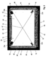
- FIG. 1 shows a schematic representation and a perspective view of a cabinet with a cabinet housing 10.
- the cabinet housing 1.0 is limited at its top 12 by an upper, horizontally extending to (not shown) bottom cover plate 14.
- the cabinet has a cabinet door 13, which are hinged to mounted on the cabinet housing hinges 53.
- the cabinet housing 10 is placed with its downwardly open bottom frame 50 on a pedestal 51, with which the cabinet is placed on the floor.
- a weatherproof roof 19 is placed on the upper horizontal cover plate 14, which is detachably connected to the cabinet housing 10. The roof 19 covers in (in FIG. 1 not shown) assembled the transport eyelets 18 from.
- FIG. 2 shows a schematic representation and in plan view of a control cabinet according to a first preferred embodiment, in which the roof 19 placed on the upper horizontal cover plate 14 of the control cabinet housing 10 and by angle elements 20a, 20b of a first type (hereinafter referred to FIG. 3 is described in more detail) is secured.
- the angle elements 22a and 22b of a first type different from the second type (hereinafter referred to FIG. 4 described) are not used to secure the roof 19, but are designed exclusively as a transport or crane loops.
- the roof plate of the roof 19 is in the representation of FIG. 2 omitted to view the look on the edge profile 36 formed on the roof 19 and the arrangement of the angle elements 20a, 20b of the first type and the angle elements 22a, 22b of the second type.
- Two angle elements 20a and 20b of the first type are arranged on the upper horizontal cover plate 14 in the region of the rear wall 46 facing away from the control cabinet door 13 in the associated corner regions of the cover plate 14.
- Two angle elements 22a and 22b of the second type are arranged on the upper horizontal cover plate 14 in the region of the control cabinet door 13 of the control cabinet housing 10 in the associated corner regions of the cover plate 14 and fastened there.
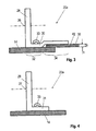
- FIG. 3 shows a schematic representation and in a partially sectioned side view in the FIG. 2 illustrated angle element 20a of the first type.
- the in the FIG. 2 shown angle elements 20a and 20b are the same. The following is based on the FIG. 3 only the angle elements 20a described.
- From the upper horizontal cover plate 14 is perpendicular to a leg 28 protrudes.
- the leg 28 is provided with a perpendicular thereto through-hole 26 for engaging carabiners.
- the fastening leg 30 has, adjacent to the leg 28, a fastening region 32 with which the angle element 20a is attached to the upper horizontal cover plate 14 of the control cabinet housing 10.
- a rivet 33 indicated.
- a (not shown) screw or welded connection could be provided.
- this has adjacent to the mounting portion 32, a holding portion 34, with which the mounting leg 30 engages behind an integrally formed on the roof 19 edge profile 36.
- the holding region 34 can be resiliently biased in an embodiment (not shown) with respect to the edge profile 36, so that in the installed state of the roof, a back pressure acts on the edge profile 36.
- the holding portion 34 of the mounting leg 30 is spaced from the upper horizontal cover plate 14 of the control cabinet housing 10 at a distance a, which substantially corresponds to the height h of the edge profile 36 of the roof 19.
- the distance a between the holding portion 34 of the mounting leg 30 and the cover plate 14 may be slightly larger than the height h of the edge profile 36 designed so that the edge profile 36 can engage in the distance range between the holding portion 34 of the mounting leg 30 and the cover plate 14 and also a tilted insertion of the edge profile 36 is possible.
- the holding portion 34 of the mounting leg 30 may (in an alternative embodiment not shown) project completely beyond the cover plate 14. In this case, the attachment region of the roof 19 in the region of the attachment leg 30 can be cut free so that the assembly process can be carried out by a tilting movement.
- the mounting leg 30 may be angled downwardly in the holding area 34, so that the mounting can be carried out as in the embodiment described above via a tilting operation, but in the mounted state via a spring action the roof 19 with a small back pressure is firmly secured to the cover plate 14 of the housing
- FIG. 2 in connection with the FIG. 3 shows, in the region of the rear wall 46 of the cabinet at the upper horizontal cover plate 14 arranged angle elements 20a and 20b of the first type with a portion of the holding portion 34 of the respective mounting leg 30 on the perimeter of the upper horizontal cover plate 14 of the cabinet housing 10 out.
- the support 42 of the edge profile 36 is defined between the mounting legs 30 of the two angle elements 20 a and 20 b and the upper horizontal cover plate 14 of the control cabinet housing 10.
- the roof 19 can be for mounting in a (not shown) shifted back position on the upper horizontal cover plate 14 of the control cabinet housing 10, with a tilt is possible, in which the front, the Cabinet door facing part of the roof 19 opposite the rear, the rear wall 46 facing part is raised.
- the support 42 of the edge profile 36 of the roof 19 is arranged in the direction away from the rear wall 46 perpendicular direction forward sparing.
- the support 42 of the edge profile 36 is not engaged with the holding portions 34 of the mounting legs 30 of the angle elements 20a and 20b.
- the support 42 of the edge profile 36 comes with the holding portions 34 of the mounting leg 30 of the angle elements 20 a and 20 b into engagement.
- FIG. 4 shows a schematic representation and in a partially sectioned side view in the FIG. 2 illustrated angle element 22a of the second type.
- the in the FIG. 2 shown angle elements 22a and 22b are the same. The following is based on the FIG. 4 only the angle elements 22a described.
- From the upper horizontal cover plate 14 is perpendicular a leg 29 protrudes.
- the leg 29 is provided with a perpendicular thereto through-hole 27 for engaging a carabiner.
- Parallel to the upper horizontal cover plate 14 extends a mounting leg 31, which adjoins the leg 29 at right angles.
- the angle element 22a of the second type is similar to that in FIG FIG. 3 shown angle element 20a of the first type.
- angle element 22a of the second type is in contrast to that in the FIG. 3 shown angle element 20a of the first type of the entire mounting leg 31 on the upper horizontal cover plate 14 of the control cabinet housing 10 and is fixed thereto.
- a rivet 33 indicated in the in the FIG. 4 embodiment shown again a rivet 33 indicated.
- a screw or welded connection could be provided.
- FIG. 5 shows a schematic representation and sectional side view of the roof area of the in FIG. 2 shown control cabinet.
- the roof 19 has a flat roof plate 38, which protrudes circumferentially beyond the upper horizontal cover plate 14 of the control cabinet housing 10 with an edge profile 36, as shown in the FIG. 2 becomes clear.
- the edge profile 36 has a circumferential, perpendicular to the upper horizontal cover plate 14 of the control cabinet housing 10 aligned soabkantung 40.
- the Soabkantung 40 has a perpendicular thereto in the direction of the center M of the upper horizontal cover plate 14 of the control cabinet housing 10 and parallel thereto support 42. With the support 42, the roof 19 rests on the edge region of the upper horizontal cover plate 14 of the control cabinet housing 10.
- the upper horizontal cover plate 14 rests on an upper frame of the control cabinet housing 10, of which in the illustration of FIG. 5 the upper depth stay 60 is shown.
- the support 42 has a plurality of ventilation slots 44, which are arranged in areas 45 which extend parallel to the cabinet door 13, the rear wall 46 and the side plates 48 of the control cabinet housing 10.
- the ventilation slots 44 extend perpendicular to the cabinet door 13, to the rear wall 46 and to the side plates 48 of the control cabinet housing 10.
- the legs 28 of the angle elements 20a, 20b and 22a, 22b are substantially in the direction of the two in the FIG. 2 drawn diagonals D1 and D2 of the upper horizontal cover plate 14 aligned.
- FIG. 6 shows in a schematic representation and sectional side view of the in FIG. 5 marked part IV in an enlarged view.
- the cabinet door beats in the in FIG. 6 shown closed position on a mounted on the cabinet housing 10, around the door opening encircled seal 62 at.
- the cabinet door has a door tube frame 64 to which the door panel is secured by a bolt 66 welded thereto.
- the upper horizontal cover plate 14 of the control cabinet housing 10 associated edge of the cabinet door 13 is bent perpendicularly in the direction of the cabinet housing 10, whereby a fold 55 is formed.
- a perpendicular thereto in the direction of the base 51 extending bevelled end portion 68 is formed.
- the perpendicular to the roof 19 in the direction of the bottom frame of the cabinet extending locking lug 52 is bent at its lower end perpendicular to the cabinet door 13, whereby a fold 57 is formed.
- a bevelled end region 70 which extends perpendicularly in the direction of the roof 19, is in turn formed.
- the support 42 of the edge profile 36 is in the area between the two angle elements 20a and 20b with a projecting support portion 56 toward the center M of the upper horizontal cover plate 14 of the control cabinet housing 10 and forms a widened support surface 47 of the roof 19 on the Edge region of the cover plate 14th
- FIG. 7 shows a schematic representation and in plan view of a control cabinet according to a second preferred embodiment, in which a roof 19 is placed on the upper horizontal cover plate 14 of the control cabinet housing 10 and secured by angle elements 24a, 24b, 24c and 24d.
- the roof panel is also in the representation of FIG. 7 omitted to view the look on the roof 19 molded edge profile 36 and the arrangement of the four angle elements 24a, 24b, 24c and 24d of the first type.
- FIG. 7 shows components already in the FIG. 2 have been given the same reference numerals and above in connection with the FIG. 2 have been described. These components are not described again below, because they have the same functionality as in the FIG. 2 shown components with the same reference numerals. Below are just the differences to the in FIG. 2 illustrated embodiment described.
- Two angle elements 24a and 24b of the basis of FIG. 3 already described first type are arranged on the upper horizontal cover plate 14 in the region of the rear wall 46 in the associated corner regions of the cover plate 14.
- Two further angle elements 24c and 24c of the same first type are arranged in the area of the control cabinet door 13 in the associated corner regions of the cover plate 14.
- the angle elements 24a, 24b, 24c and 24d have as the basis of the FIG. 3 described angle element 20a mounting leg 30 which rest with their mounting portions 32 on the upper horizontal cover plate 14 of the control cabinet housing 10 and secured thereto.
- the holding regions 34 are spaced from the upper horizontal cover plate 14 of the control cabinet housing 10, wherein the support 42 of the edge profile 36 between the mounting legs 30 of the angle elements 24a, 24b, 24c and 24d and the upper horizontal cover plate 14 of the control cabinet housing 10 are fixed.
- the support 42 of the edge profile 36 has four recesses 58, which are offset in the direction of the rear wall 46 of the control cabinet housing 10 and adjacent to the angle elements 24a, 24b, 24c and 24d are formed.
- the recesses 58 are formed corresponding to the holding portions 34 of the fastening legs 30 of the angle elements 24a, 24b, 24c and 24d.
- the roof 19 can be placed in a (not shown) position on the upper horizontal cover plate 14 of the control cabinet housing 10 so that the recesses 58 in the support 42 of the edge profile 36 with the holding portions 34 of the mounting leg 30 of the angle elements 24a, 24b , 24c and 24d are in cover. In this position, the support 42 of the edge profile 36 with the holding portions 34 of the mounting leg 30 of the angle elements 24a, 24b, 24c and 24d is disengaged.
- the support 42 of the edge profile 36 can be brought into engagement with the holding areas 34 of the fastening legs 30 of the angle elements 24a, 24b, 24c and 24d.
Landscapes
- Engineering & Computer Science (AREA)
- Power Engineering (AREA)
- Patch Boards (AREA)
- Casings For Electric Apparatus (AREA)
Claims (19)
- Armoire électrique, comportant un caisson d'armoire (10) qui est délimité sur sa face supérieure (12) par une plaque de recouvrement supérieure (14) et comporte au moins une porte (13) sur sa face avant (16), une pluralité de boucles de transport (18) étant disposées sur la face supérieure (12) dudit caisson d'armoire (10), lesquelles peuvent être masquées par une paroi supérieure (19) pouvant être fixée de manière amovible,
caractérisée en ce que les boucles de transport (18) sont formées par des cornières (20a, 20b, 22a, 22b ; 24a, 24b, 24c, 24d) qui comportent chacune une branche (28 ; 29), en saillie sur la plaque de recouvrement supérieure (14) et munie d'une forure débouchante (26 ; 27), et une branche de fixation (30 ; 31) disposée en angle par rapport à ladite branche saillante, lesdites branches de fixation (30 ; 31) d'au moins une partie des cornières (20a, 20b ; 24a, 24b, 24c, 24d) comportant chacune une zone de fixation (32), par laquelle elles sont attachées à la face supérieure (12) du caisson d'armoire (10), et une zone de retenue (34) par laquelle elles s'engagent derrière un profilé de bordure (36) formé sur la paroi supérieure (19). - Armoire électrique selon la revendication 1, caractérisée en ce que la zone de retenue (34) est précontrainte de manière élastique par rapport au profilé de bordure (36), de telle sorte que, dans la position montée de la paroi supérieure, une contrepression s'exerce sur le profilé de bordure (36).
- Armoire électrique selon la revendication 1 ou 2, caractérisée en ce qu'au moins une partie des cornières (22a, 22b) comportent une branche (29), en saillie sur la plaque de recouvrement supérieure (14) et munie d'une forure débouchante (27), et une branche de fixation (31) disposée en angle par rapport à ladite branche saillante, lesdites branches de fixation (31) étant en appui contre la plaque de recouvrement supérieure (14) du caisson d'armoire (10) et étant fixées à celle-ci.
- Armoire électrique selon l'une quelconque des revendications 1 à 3, caractérisée en ce que les branches (28) des cornières (20a, 20b, 22a, 22b ; 24a, 24b, 24c, 24d) sont dirigées sensiblement dans la direction des diagonales (D1 ; D2) de la plaque de recouvrement supérieure (14).
- Armoire électrique selon l'une quelconque des revendications 1 à 4, caractérisée en ce que la paroi supérieure (19) comporte une plaque (38) plane, dont le pourtour s'avance en saillie au-delà de la plaque de recouvrement supérieure (14) du caisson d'armoire (10) avec un profilé de bordure (36) qui comporte un biseau latéral (40), qui est dirigé vers la plaque de recouvrement supérieure (14) du caisson d'armoire (10) et qui, pour sa part, comporte une surface d'appui (42), qui est biseautée par rapport audit biseau latéral vers le milieu (M) de la plaque de recouvrement supérieure (14) du caisson d'armoire (10) et par laquelle la paroi supérieure (19) est en appui sur la zone de bordure de la plaque de recouvrement supérieure (14) du caisson d'armoire (10).
- Armoire électrique selon la revendication 5, caractérisée en ce que ladite surface d'appui (42) comporte des fentes d'aération (44) qui sont agencées dans des zones (45) qui s'étendent au moins en partie parallèlement à la porte (13), à la paroi arrière (46) et aux plaques latérales (48) du caisson d'armoire (10).
- Armoire électrique selon la revendication 6, caractérisée en ce qu'une pluralité de fentes d'aération (44) s'étendent perpendiculairement à la porte (13), à la paroi arrière (46) et aux plaques latérales (48) du caisson d'armoire (10).
- Armoire électrique selon la revendication 1, caractérisée en ce que la surface d'appui (42) du profilé de bordure (36) est fixée entre les branches de fixation (30) d'au moins deux cornières (20a, 20b ; 24a, 24b, 24c, 24d) et la plaque de recouvrement supérieure (14) du caisson d'armoire (10).
- Armoire électrique selon l'une quelconque des revendications 1 à 8, caractérisée en ce qu'au moins deux des cornières (20a, 20b) s'avancent avec au moins une partie des zones de retenue (34) des branches de fixation (30) au-delà de la limite périphérique de la plaque de recouvrement supérieure (14) du caisson d'armoire (10).
- Armoire électrique selon l'une quelconque des revendications 5 à 9, caractérisée en ce qu'au niveau de la zone, orientée vers la porte (13), du profilé de bordure (36) de la paroi supérieure (19) est formée une saillie de verrouillage (52) qui s'étend à partir de la paroi supérieure (19) vers le cadre de fond (50) de ladite armoire électrique et qui s'étend vers l'intérieur de la zone d'écartement (54) entre la porte (13) et le caisson d'armoire (10), de manière à empêcher, lorsque la porte (13) est fermée, un déplacement de la paroi supérieure (19) par rapport à la plaque de recouvrement supérieure (14) vers la porte (13).
- Armoire électrique selon la revendication 10, caractérisée en ce que le bord de la porte (13), orienté vers la plaque de recouvrement supérieure (14) du caisson d'armoire (10), est biseauté (biseau 55) vers le caisson d'armoire (10), et la saillie de verrouillage (52), qui s'étend à partir de la paroi supérieure (19) vers le cadre de fond de ladite armoire électrique, est biseautée (biseau 57) au niveau de son extrémité inférieure vers la porte (13).
- Armoire électrique selon l'une quelconque des revendications 5 à 11, caractérisée en ce que la zone de fixation (32) de la branche de fixation (30) de la cornière (20a, 20b ; 24a, 24b, 24c, 24d) est en appui sur la plaque de recouvrement supérieure (14) du caisson d'armoire (10) et est fixée à celle-ci, la zone de retenue (34) de la branche de fixation (30) étant écartée de la plaque de recouvrement supérieure (14) du caisson d'armoire (10) selon une distance (a) qui correspond sensiblement à la hauteur (h) de la surface d'appui (42) du profilé de bordure (36) de la paroi supérieure (19).
- Armoire électrique selon l'une quelconque des revendications 5 à 12, caractérisée en ce qu'au moins deux premières cornières (20a, 20b) avec des branches de fixation (30), qui sont en appui avec leurs zones de fixation (32) sur la plaque de recouvrement supérieure (14) du caisson d'armoire (10) et sont fixées contre celle-ci et qui avec leurs zones de retenue (34) sont écartées de la plaque de recouvrement supérieure (14) du caisson d'armoire (10), sont disposées sur la plaque de recouvrement supérieure (14) dans la zone de la paroi arrière (46) détournée de la porte (13), lesdites zones de retenue (34) s'avançant au-delà de la limite périphérique de la plaque de recouvrement supérieure (14), et la surface d'appui (42) du profilé de bordure (36) pouvant être immobilisée entre les branches de fixation (30) des deux premières cornières (20a, 20b) et la plaque de recouvrement supérieure (14) du caisson d'armoire (10), et au moins deux deuxièmes cornières (22a, 22b) avec les branches de fixation (31), qui sont en appui sur la plaque de recouvrement supérieure (14) du caisson d'armoire (10), sont disposées et fixées contre la plaque de recouvrement supérieure (14) dans la zone de la porte (13) du caisson d'armoire (10).
- Armoire électrique selon la revendication 13, caractérisée en ce que la surface d'appui (42) du profilé de bordure (36), dans la zone entre les deux premières cornières (20a, 20b), s'avance en saillie avec une zone d'appui (56) saillante vers le milieu de la plaque de recouvrement supérieure (14) du caisson d'armoire (10) et forme une surface d'appui (47) élargie.
- Armoire électrique selon la revendication 13 ou 14, caractérisée en ce que la paroi supérieure (19) peut être posée, en vue du montage, sur la plaque de recouvrement supérieure (14) du caisson d'armoire (10), de telle sorte que la surface d'appui (42), agencée dans la zone de la paroi arrière (46) détournée de la porte (13), du profilé de bordure (36) de la paroi supérieure (19) est agencée dans une direction orientée en s'écartant de la paroi arrière (46), ladite surface d'appui (42) du profilé de bordure (36) étant hors de prise avec les zones de retenue (34) des branches de fixation (30) des premières cornières (20a, 20b), et ladite paroi supérieure (19) pouvant être coulissée vers la porte (13), de telle sorte que la surface d'appui (42) du profilé de bordure (36) peut être amenée en prise avec les zones de retenue (34) des branches de fixation (30) des premières cornières (20a, 20b).
- Armoire électrique selon l'une quelconque des revendications 5 à 12, caractérisée en ce qu'au moins deux cornières (24a, 24b) sont disposées au niveau de la plaque de recouvrement supérieure (14) dans la zone de la paroi arrière (46) détournée de la porte (13), et au moins deux autre cornières (24c, 24d) sont disposées dans la zone de la porte (13) du caisson d'armoire (10), lesdits cornières (24a, 24b, 24c, 24d) comportant des branches de fixation (30) qui, avec leurs zones de fixation (32), sont en appui sur la plaque de recouvrement supérieure (14) du caisson d'armoire (10) et sont fixées à celle-ci, et qui, avec leurs zones de retenue (34), sont écartées de la plaque de recouvrement supérieure (14) du caisson d'armoire (10), la surface d'appui (42) du profilé de bordure (36) pouvant être immobilisée entre les branches de fixation (30) des cornières (24a, 24b, 24c, 24d) et la plaque de recouvrement supérieure (14) du caisson d'armoire (10).
- Armoire électrique selon la revendication 16, caractérisée en ce que la surface d'appui (42) du profilé de bordure (36) comporte des évidements (58), qui sont ménagés dans la direction de la paroi arrière (46) du caisson d'armoire (10) à proximité des cornières (24a, 24b, 24c, 24d) et en correspondance avec les zones de retenue (34) des branches de fixation (30) des cornières (24a, 24b, 24c, 24d).
- Armoire électrique selon la revendication 16 ou 17, caractérisée en ce que la paroi supérieure (19) peut être posée, en vue du montage, sur la plaque de recouvrement supérieure (14) du caisson d'armoire (10) de telle sorte que les évidements (58) dans la surface d'appui (42) du profilé de bordure (36) coïncident avec les zones de retenue (34) des branches de fixation (30) des cornières (24a, 24b, 24c, 24d), ladite surface d'appui (42) du profilé de bordure (36) étant hors de prise des zones de retenue (34) des branches de fixation (30) des cornières, et la paroi supérieure (19) pouvant être coulissée vers la paroi arrière (46) du caisson d'armoire (10), de telle sorte que la surface d'appui (42) du profilé de bordure (36) peut être amenée en prise avec les zones de retenue (34) des branches de fixation (30) des cornières (24a, 24b, 24c, 24d).
- Armoire électrique selon la revendication 18, caractérisée en ce que la saillie de verrouillage (52), qui s'étend à partir de la paroi supérieure (19) vers le cadre de fond (50) du caisson d'armoire (10), vient buter contre le caisson d'armoire (10) lors du coulissement de la paroi supérieure (19) vers la paroi arrière (46) du caisson d'armoire (10).
Priority Applications (1)
| Application Number | Priority Date | Filing Date | Title |
|---|---|---|---|
| PL08018630T PL2065990T3 (pl) | 2007-11-27 | 2008-10-24 | Szafa rozdzielcza |
Applications Claiming Priority (1)
| Application Number | Priority Date | Filing Date | Title |
|---|---|---|---|
| DE102007057381A DE102007057381B4 (de) | 2007-11-27 | 2007-11-27 | Schaltschrank |
Publications (3)
| Publication Number | Publication Date |
|---|---|
| EP2065990A2 EP2065990A2 (fr) | 2009-06-03 |
| EP2065990A3 EP2065990A3 (fr) | 2013-02-27 |
| EP2065990B1 true EP2065990B1 (fr) | 2013-10-16 |
Family
ID=40383661
Family Applications (1)
| Application Number | Title | Priority Date | Filing Date |
|---|---|---|---|
| EP08018630.7A Active EP2065990B1 (fr) | 2007-11-27 | 2008-10-24 | Armoire électrique |
Country Status (5)
| Country | Link |
|---|---|
| US (1) | US20090145622A1 (fr) |
| EP (1) | EP2065990B1 (fr) |
| CN (1) | CN101447652A (fr) |
| DE (1) | DE102007057381B4 (fr) |
| PL (1) | PL2065990T3 (fr) |
Families Citing this family (11)
| Publication number | Priority date | Publication date | Assignee | Title |
|---|---|---|---|---|
| USD619992S1 (en) * | 2007-03-27 | 2010-07-20 | Adc Telecommunications, Inc. | Chassis for electronic circuitry |
| USD621812S1 (en) * | 2007-03-27 | 2010-08-17 | Adc Telecommunications, Inc. | Chassis for electronic circuitry |
| CN102810819A (zh) * | 2011-05-30 | 2012-12-05 | 苏州市吴中区东方成套电器设备有限公司 | 一种低压电气柜 |
| CN103579916B (zh) * | 2012-07-18 | 2016-02-10 | 南车青岛四方机车车辆股份有限公司 | 一种配电柜 |
| DK2993746T3 (en) * | 2014-09-05 | 2018-08-13 | Celsion Brandschutzsysteme Gmbh | Portable fire protection system for electrical systems |
| CN104876078A (zh) * | 2015-06-05 | 2015-09-02 | 苏州德朗控制技术有限公司 | 一种可扩展式电梯控制柜 |
| DE202016103381U1 (de) | 2016-06-27 | 2016-08-17 | Rittal Gmbh & Co. Kg | Schaltschrankgehäuse für die seitliche Montage einer Versorgungssäule und eine entsprechende Schaltschrankanordnung |
| DE102020125017B4 (de) | 2020-09-25 | 2024-09-12 | Envola GmbH | Installationsvorrichtung mit Modulen der Energie- oder Gebäudetechnik sowie Verfahren zur Entnahme eines Moduls aus einer derartigen Installationsvorrichtung |
| CN112787241B (zh) * | 2020-12-29 | 2022-09-27 | 国网浙江省电力有限公司台州供电公司 | 一种防盗配电柜 |
| CN114256758B (zh) * | 2021-12-09 | 2024-03-19 | 江苏中顺电气有限公司 | 一种便于拆解运输的电器柜 |
| USD1105027S1 (en) * | 2023-03-07 | 2025-12-09 | Communications Research & IP Holdings Ltd | Housing for communications equipment |
Family Cites Families (7)
| Publication number | Priority date | Publication date | Assignee | Title |
|---|---|---|---|---|
| DE4413819C1 (de) * | 1994-04-20 | 1995-04-20 | Kautz Starkstrom Anlagen Gmbh | Mit den oberen Ecken eines Schaltschrankes verbindbare Anhängevorrichtung |
| DE29509555U1 (de) * | 1995-06-10 | 1995-08-24 | Dessauer Schaltschrankbau GmbH, 06847 Dessau | Schaltschrank mit Montageplatte als Einzel- oder Anreihschrank |
| DE19748234C2 (de) * | 1997-10-31 | 2002-02-28 | Rittal Gmbh & Co Kg | Schaltschrank |
| DE19914408B4 (de) * | 1999-03-30 | 2006-07-13 | Deutsche Telekom Ag | Geräteschrank |
| US6365826B1 (en) * | 1999-12-22 | 2002-04-02 | General Electric Company | Waterproof enclosure for electrical devices |
| US7498512B2 (en) * | 2006-03-13 | 2009-03-03 | Panduit Corp. | Network cabinet |
| US7659476B2 (en) * | 2007-04-30 | 2010-02-09 | Adc Telecommunication, Inc. | Frame arrangement for a telecommunications cabinet |
-
2007
- 2007-11-27 DE DE102007057381A patent/DE102007057381B4/de active Active
-
2008
- 2008-10-24 PL PL08018630T patent/PL2065990T3/pl unknown
- 2008-10-24 EP EP08018630.7A patent/EP2065990B1/fr active Active
- 2008-11-17 US US12/313,373 patent/US20090145622A1/en not_active Abandoned
- 2008-11-27 CN CNA2008101774521A patent/CN101447652A/zh active Pending
Also Published As
| Publication number | Publication date |
|---|---|
| DE102007057381A1 (de) | 2009-06-04 |
| EP2065990A3 (fr) | 2013-02-27 |
| PL2065990T3 (pl) | 2014-03-31 |
| CN101447652A (zh) | 2009-06-03 |
| US20090145622A1 (en) | 2009-06-11 |
| DE102007057381B4 (de) | 2011-12-08 |
| EP2065990A2 (fr) | 2009-06-03 |
Similar Documents
| Publication | Publication Date | Title |
|---|---|---|
| EP2065990B1 (fr) | Armoire électrique | |
| EP3477802B1 (fr) | Dispositif de stabilisation pour le transport d'une armoire de commande | |
| DE69425993T2 (de) | Vorrichtung zur Ausdehnung von Trennwänden | |
| EP3566270B1 (fr) | Ensemble plaque de montage et procédé correspondant | |
| EP3217099B1 (fr) | Hotte aspirante | |
| DE102010022845B4 (de) | Kantenschutzelement für die Anordnung ungerahmter PV-Module | |
| EP2628411B1 (fr) | Tiroir | |
| EP3545793B1 (fr) | Meuble formé de pièces profilées s'étendant verticalement et horizontalement ainsi que meuble pourvu d'au moins deux parois latérales | |
| EP3231962B1 (fr) | Sécurité anti-chute pour des personnes comprenant une plaque de sécurité dotée de griffes | |
| EP3607624B1 (fr) | Ensemble comprenant un socle et un châssis pour armoire électrique ainsi qu'une rangée d'armoires électriques | |
| WO2018138033A1 (fr) | Panneau solaire avec éléments de ferrure multifonctions et éléments de ferrure multifonctions | |
| EP1965625B1 (fr) | Support variable | |
| EP2114200B1 (fr) | Pupitre de commande | |
| DE202018106077U1 (de) | Glasträgerkonstruktion und Rahmenkonstruktion | |
| EP2998458B1 (fr) | Dispositif de fixation d'une plaque sur une base d'ancrage | |
| DE102007014786B4 (de) | Bodenblechanordnung für einen Schaltschrank | |
| EP3605763B1 (fr) | Cage souterraine, en particulier pour la distribution d'énergie et/ou la télécommunication | |
| EP0602378B1 (fr) | Dispositif de montage pour hottes d'évacuation de fumées encastrées ou annexes à des éléments d'armoire suspendue | |
| DE202012102863U1 (de) | Befestigungseinrichtung für ein Flächenelement an einem C-Profil | |
| DE2615671C2 (de) | Verriegelungsblende zur Sicherung elektronischer Baugruppen | |
| EP1128346A2 (fr) | Socle réglable en hauteur pour machines de transactions et analogues | |
| EP2947226B1 (fr) | Fenêtre de toit d'habitation dotée d'une zinguerie destinée à recouvrir des zones extérieures d'un chambranle et d'un dormant | |
| EP2258237B1 (fr) | Tiroir coulissant fabriqué en métal ou en plastique | |
| EP2586928B1 (fr) | Support de plaque en particulier pour panneaux en verre | |
| EP2080852A1 (fr) | Plateforme d'échafaudage dotée d'un clapet de passage dont l'angle de pivotement est limité |
Legal Events
| Date | Code | Title | Description |
|---|---|---|---|
| PUAI | Public reference made under article 153(3) epc to a published international application that has entered the european phase |
Free format text: ORIGINAL CODE: 0009012 |
|
| AK | Designated contracting states |
Kind code of ref document: A2 Designated state(s): AT BE BG CH CY CZ DE DK EE ES FI FR GB GR HR HU IE IS IT LI LT LU LV MC MT NL NO PL PT RO SE SI SK TR |
|
| AX | Request for extension of the european patent |
Extension state: AL BA MK RS |
|
| PUAL | Search report despatched |
Free format text: ORIGINAL CODE: 0009013 |
|
| AK | Designated contracting states |
Kind code of ref document: A3 Designated state(s): AT BE BG CH CY CZ DE DK EE ES FI FR GB GR HR HU IE IS IT LI LT LU LV MC MT NL NO PL PT RO SE SI SK TR |
|
| AX | Request for extension of the european patent |
Extension state: AL BA MK RS |
|
| RIC1 | Information provided on ipc code assigned before grant |
Ipc: H02B 1/30 20060101AFI20130122BHEP |
|
| 17P | Request for examination filed |
Effective date: 20130205 |
|
| GRAP | Despatch of communication of intention to grant a patent |
Free format text: ORIGINAL CODE: EPIDOSNIGR1 |
|
| INTG | Intention to grant announced |
Effective date: 20130503 |
|
| GRAS | Grant fee paid |
Free format text: ORIGINAL CODE: EPIDOSNIGR3 |
|
| GRAA | (expected) grant |
Free format text: ORIGINAL CODE: 0009210 |
|
| AK | Designated contracting states |
Kind code of ref document: B1 Designated state(s): AT BE BG CH CY CZ DE DK EE ES FI FR GB GR HR HU IE IS IT LI LT LU LV MC MT NL NO PL PT RO SE SI SK TR |
|
| RBV | Designated contracting states (corrected) |
Designated state(s): AT BE BG CH CY CZ DE DK EE ES FI FR GB GR HR HU IE IS IT LI LT LU LV MC MT NL NO PL PT RO SE SI SK TR |
|
| REG | Reference to a national code |
Ref country code: GB Ref legal event code: FG4D Free format text: NOT ENGLISH |
|
| AKX | Designation fees paid |
Designated state(s): AT BE BG CH CY CZ DE DK EE ES FI FR GB GR HR HU IE IS IT LI LT LU LV MC MT NL NO PL PT RO SE SI SK TR |
|
| REG | Reference to a national code |
Ref country code: CH Ref legal event code: EP |
|
| REG | Reference to a national code |
Ref country code: IE Ref legal event code: FG4D Free format text: LANGUAGE OF EP DOCUMENT: GERMAN |
|
| REG | Reference to a national code |
Ref country code: AT Ref legal event code: REF Ref document number: 636899 Country of ref document: AT Kind code of ref document: T Effective date: 20131115 |
|
| REG | Reference to a national code |
Ref country code: DE Ref legal event code: R096 Ref document number: 502008010802 Country of ref document: DE Effective date: 20131212 |
|
| REG | Reference to a national code |
Ref country code: NL Ref legal event code: VDEP Effective date: 20131016 |
|
| REG | Reference to a national code |
Ref country code: LT Ref legal event code: MG4D |
|
| BERE | Be: lapsed |
Owner name: RITTAL G.M.B.H. Effective date: 20131031 |
|
| PG25 | Lapsed in a contracting state [announced via postgrant information from national office to epo] |
Ref country code: NO Free format text: LAPSE BECAUSE OF FAILURE TO SUBMIT A TRANSLATION OF THE DESCRIPTION OR TO PAY THE FEE WITHIN THE PRESCRIBED TIME-LIMIT Effective date: 20140116 Ref country code: LT Free format text: LAPSE BECAUSE OF FAILURE TO SUBMIT A TRANSLATION OF THE DESCRIPTION OR TO PAY THE FEE WITHIN THE PRESCRIBED TIME-LIMIT Effective date: 20131016 Ref country code: HR Free format text: LAPSE BECAUSE OF FAILURE TO SUBMIT A TRANSLATION OF THE DESCRIPTION OR TO PAY THE FEE WITHIN THE PRESCRIBED TIME-LIMIT Effective date: 20131016 Ref country code: NL Free format text: LAPSE BECAUSE OF FAILURE TO SUBMIT A TRANSLATION OF THE DESCRIPTION OR TO PAY THE FEE WITHIN THE PRESCRIBED TIME-LIMIT Effective date: 20131016 Ref country code: IS Free format text: LAPSE BECAUSE OF FAILURE TO SUBMIT A TRANSLATION OF THE DESCRIPTION OR TO PAY THE FEE WITHIN THE PRESCRIBED TIME-LIMIT Effective date: 20140216 Ref country code: FI Free format text: LAPSE BECAUSE OF FAILURE TO SUBMIT A TRANSLATION OF THE DESCRIPTION OR TO PAY THE FEE WITHIN THE PRESCRIBED TIME-LIMIT Effective date: 20131016 Ref country code: SE Free format text: LAPSE BECAUSE OF FAILURE TO SUBMIT A TRANSLATION OF THE DESCRIPTION OR TO PAY THE FEE WITHIN THE PRESCRIBED TIME-LIMIT Effective date: 20131016 |
|
| PG25 | Lapsed in a contracting state [announced via postgrant information from national office to epo] |
Ref country code: LV Free format text: LAPSE BECAUSE OF FAILURE TO SUBMIT A TRANSLATION OF THE DESCRIPTION OR TO PAY THE FEE WITHIN THE PRESCRIBED TIME-LIMIT Effective date: 20131016 Ref country code: ES Free format text: LAPSE BECAUSE OF FAILURE TO SUBMIT A TRANSLATION OF THE DESCRIPTION OR TO PAY THE FEE WITHIN THE PRESCRIBED TIME-LIMIT Effective date: 20131016 Ref country code: CY Free format text: LAPSE BECAUSE OF FAILURE TO SUBMIT A TRANSLATION OF THE DESCRIPTION OR TO PAY THE FEE WITHIN THE PRESCRIBED TIME-LIMIT Effective date: 20131016 |
|
| REG | Reference to a national code |
Ref country code: CH Ref legal event code: PL |
|
| PG25 | Lapsed in a contracting state [announced via postgrant information from national office to epo] |
Ref country code: PT Free format text: LAPSE BECAUSE OF FAILURE TO SUBMIT A TRANSLATION OF THE DESCRIPTION OR TO PAY THE FEE WITHIN THE PRESCRIBED TIME-LIMIT Effective date: 20140217 |
|
| REG | Reference to a national code |
Ref country code: DE Ref legal event code: R119 Ref document number: 502008010802 Country of ref document: DE Effective date: 20140501 |
|
| REG | Reference to a national code |
Ref country code: IE Ref legal event code: MM4A |
|
| PG25 | Lapsed in a contracting state [announced via postgrant information from national office to epo] |
Ref country code: EE Free format text: LAPSE BECAUSE OF FAILURE TO SUBMIT A TRANSLATION OF THE DESCRIPTION OR TO PAY THE FEE WITHIN THE PRESCRIBED TIME-LIMIT Effective date: 20131016 Ref country code: CH Free format text: LAPSE BECAUSE OF NON-PAYMENT OF DUE FEES Effective date: 20131031 Ref country code: LI Free format text: LAPSE BECAUSE OF NON-PAYMENT OF DUE FEES Effective date: 20131031 Ref country code: MC Free format text: LAPSE BECAUSE OF FAILURE TO SUBMIT A TRANSLATION OF THE DESCRIPTION OR TO PAY THE FEE WITHIN THE PRESCRIBED TIME-LIMIT Effective date: 20131016 |
|
| PLBE | No opposition filed within time limit |
Free format text: ORIGINAL CODE: 0009261 |
|
| STAA | Information on the status of an ep patent application or granted ep patent |
Free format text: STATUS: NO OPPOSITION FILED WITHIN TIME LIMIT |
|
| PG25 | Lapsed in a contracting state [announced via postgrant information from national office to epo] |
Ref country code: SK Free format text: LAPSE BECAUSE OF FAILURE TO SUBMIT A TRANSLATION OF THE DESCRIPTION OR TO PAY THE FEE WITHIN THE PRESCRIBED TIME-LIMIT Effective date: 20131016 Ref country code: DE Free format text: LAPSE BECAUSE OF NON-PAYMENT OF DUE FEES Effective date: 20140501 Ref country code: CZ Free format text: LAPSE BECAUSE OF FAILURE TO SUBMIT A TRANSLATION OF THE DESCRIPTION OR TO PAY THE FEE WITHIN THE PRESCRIBED TIME-LIMIT Effective date: 20131016 Ref country code: RO Free format text: LAPSE BECAUSE OF FAILURE TO SUBMIT A TRANSLATION OF THE DESCRIPTION OR TO PAY THE FEE WITHIN THE PRESCRIBED TIME-LIMIT Effective date: 20131016 |
|
| 26N | No opposition filed |
Effective date: 20140717 |
|
| GBPC | Gb: european patent ceased through non-payment of renewal fee |
Effective date: 20140116 |
|
| PG25 | Lapsed in a contracting state [announced via postgrant information from national office to epo] |
Ref country code: BE Free format text: LAPSE BECAUSE OF NON-PAYMENT OF DUE FEES Effective date: 20131031 Ref country code: DK Free format text: LAPSE BECAUSE OF FAILURE TO SUBMIT A TRANSLATION OF THE DESCRIPTION OR TO PAY THE FEE WITHIN THE PRESCRIBED TIME-LIMIT Effective date: 20131016 |
|
| PG25 | Lapsed in a contracting state [announced via postgrant information from national office to epo] |
Ref country code: IE Free format text: LAPSE BECAUSE OF NON-PAYMENT OF DUE FEES Effective date: 20131024 |
|
| PG25 | Lapsed in a contracting state [announced via postgrant information from national office to epo] |
Ref country code: GB Free format text: LAPSE BECAUSE OF NON-PAYMENT OF DUE FEES Effective date: 20140116 |
|
| REG | Reference to a national code |
Ref country code: AT Ref legal event code: MM01 Ref document number: 636899 Country of ref document: AT Kind code of ref document: T Effective date: 20131024 |
|
| PG25 | Lapsed in a contracting state [announced via postgrant information from national office to epo] |
Ref country code: AT Free format text: LAPSE BECAUSE OF NON-PAYMENT OF DUE FEES Effective date: 20131024 Ref country code: SI Free format text: LAPSE BECAUSE OF FAILURE TO SUBMIT A TRANSLATION OF THE DESCRIPTION OR TO PAY THE FEE WITHIN THE PRESCRIBED TIME-LIMIT Effective date: 20131016 |
|
| PG25 | Lapsed in a contracting state [announced via postgrant information from national office to epo] |
Ref country code: TR Free format text: LAPSE BECAUSE OF FAILURE TO SUBMIT A TRANSLATION OF THE DESCRIPTION OR TO PAY THE FEE WITHIN THE PRESCRIBED TIME-LIMIT Effective date: 20131016 |
|
| PG25 | Lapsed in a contracting state [announced via postgrant information from national office to epo] |
Ref country code: LU Free format text: LAPSE BECAUSE OF NON-PAYMENT OF DUE FEES Effective date: 20131024 Ref country code: HU Free format text: LAPSE BECAUSE OF FAILURE TO SUBMIT A TRANSLATION OF THE DESCRIPTION OR TO PAY THE FEE WITHIN THE PRESCRIBED TIME-LIMIT; INVALID AB INITIO Effective date: 20081024 Ref country code: BG Free format text: LAPSE BECAUSE OF FAILURE TO SUBMIT A TRANSLATION OF THE DESCRIPTION OR TO PAY THE FEE WITHIN THE PRESCRIBED TIME-LIMIT Effective date: 20131016 |
|
| PG25 | Lapsed in a contracting state [announced via postgrant information from national office to epo] |
Ref country code: MT Free format text: LAPSE BECAUSE OF FAILURE TO SUBMIT A TRANSLATION OF THE DESCRIPTION OR TO PAY THE FEE WITHIN THE PRESCRIBED TIME-LIMIT Effective date: 20131016 Ref country code: GR Free format text: LAPSE BECAUSE OF NON-PAYMENT OF DUE FEES Effective date: 20131016 |
|
| REG | Reference to a national code |
Ref country code: FR Ref legal event code: PLFP Year of fee payment: 8 |
|
| PG25 | Lapsed in a contracting state [announced via postgrant information from national office to epo] |
Ref country code: GR Free format text: LAPSE BECAUSE OF FAILURE TO SUBMIT A TRANSLATION OF THE DESCRIPTION OR TO PAY THE FEE WITHIN THE PRESCRIBED TIME-LIMIT Effective date: 20140117 |
|
| REG | Reference to a national code |
Ref country code: FR Ref legal event code: PLFP Year of fee payment: 9 |
|
| REG | Reference to a national code |
Ref country code: FR Ref legal event code: PLFP Year of fee payment: 10 |
|
| REG | Reference to a national code |
Ref country code: FR Ref legal event code: PLFP Year of fee payment: 11 |
|
| P01 | Opt-out of the competence of the unified patent court (upc) registered |
Effective date: 20230525 |
|
| PGFP | Annual fee paid to national office [announced via postgrant information from national office to epo] |
Ref country code: IT Payment date: 20251031 Year of fee payment: 18 |
|
| PGFP | Annual fee paid to national office [announced via postgrant information from national office to epo] |
Ref country code: FR Payment date: 20251027 Year of fee payment: 18 |
|
| PGFP | Annual fee paid to national office [announced via postgrant information from national office to epo] |
Ref country code: PL Payment date: 20251015 Year of fee payment: 18 |