EP2066004A1 - Moteur et compresseur - Google Patents
Moteur et compresseur Download PDFInfo
- Publication number
- EP2066004A1 EP2066004A1 EP07807148A EP07807148A EP2066004A1 EP 2066004 A1 EP2066004 A1 EP 2066004A1 EP 07807148 A EP07807148 A EP 07807148A EP 07807148 A EP07807148 A EP 07807148A EP 2066004 A1 EP2066004 A1 EP 2066004A1
- Authority
- EP
- European Patent Office
- Prior art keywords
- stator
- rotating shaft
- rotor
- radius
- motor
- Prior art date
- Legal status (The legal status is an assumption and is not a legal conclusion. Google has not performed a legal analysis and makes no representation as to the accuracy of the status listed.)
- Withdrawn
Links
- 239000000696 magnetic material Substances 0.000 claims description 74
- 230000004907 flux Effects 0.000 claims description 28
- 230000004323 axial length Effects 0.000 claims description 9
- 101100121625 Caenorhabditis elegans rhi-1 gene Proteins 0.000 claims description 8
- 101000755496 Canis lupus familiaris Transforming protein RhoA Proteins 0.000 claims description 8
- 230000000149 penetrating effect Effects 0.000 claims description 7
- 230000006835 compression Effects 0.000 description 21
- 238000007906 compression Methods 0.000 description 21
- XEEYBQQBJWHFJM-UHFFFAOYSA-N Iron Chemical compound [Fe] XEEYBQQBJWHFJM-UHFFFAOYSA-N 0.000 description 16
- 230000007246 mechanism Effects 0.000 description 16
- 238000010586 diagram Methods 0.000 description 11
- 239000003507 refrigerant Substances 0.000 description 8
- 229910052742 iron Inorganic materials 0.000 description 7
- 230000008901 benefit Effects 0.000 description 4
- 238000000034 method Methods 0.000 description 4
- 230000005347 demagnetization Effects 0.000 description 3
- 230000009467 reduction Effects 0.000 description 3
- 230000000694 effects Effects 0.000 description 2
- 230000002238 attenuated effect Effects 0.000 description 1
- 230000008859 change Effects 0.000 description 1
- 239000000428 dust Substances 0.000 description 1
- 230000002093 peripheral effect Effects 0.000 description 1
- 230000010349 pulsation Effects 0.000 description 1
- 239000011347 resin Substances 0.000 description 1
- 229920005989 resin Polymers 0.000 description 1
- 229920006395 saturated elastomer Polymers 0.000 description 1
- 238000003466 welding Methods 0.000 description 1
Images








Classifications
-
- F—MECHANICAL ENGINEERING; LIGHTING; HEATING; WEAPONS; BLASTING
- F04—POSITIVE - DISPLACEMENT MACHINES FOR LIQUIDS; PUMPS FOR LIQUIDS OR ELASTIC FLUIDS
- F04C—ROTARY-PISTON, OR OSCILLATING-PISTON, POSITIVE-DISPLACEMENT MACHINES FOR LIQUIDS; ROTARY-PISTON, OR OSCILLATING-PISTON, POSITIVE-DISPLACEMENT PUMPS
- F04C23/00—Combinations of two or more pumps, each being of rotary-piston or oscillating-piston type, specially adapted for elastic fluids; Pumping installations specially adapted for elastic fluids; Multi-stage pumps specially adapted for elastic fluids
- F04C23/008—Hermetic pumps
-
- F—MECHANICAL ENGINEERING; LIGHTING; HEATING; WEAPONS; BLASTING
- F04—POSITIVE - DISPLACEMENT MACHINES FOR LIQUIDS; PUMPS FOR LIQUIDS OR ELASTIC FLUIDS
- F04C—ROTARY-PISTON, OR OSCILLATING-PISTON, POSITIVE-DISPLACEMENT MACHINES FOR LIQUIDS; ROTARY-PISTON, OR OSCILLATING-PISTON, POSITIVE-DISPLACEMENT PUMPS
- F04C29/00—Component parts, details or accessories of pumps or pumping installations, not provided for in groups F04C18/00 - F04C28/00
- F04C29/0042—Driving elements, brakes, couplings, transmissions specially adapted for pumps
- F04C29/0085—Prime movers
-
- H—ELECTRICITY
- H02—GENERATION; CONVERSION OR DISTRIBUTION OF ELECTRIC POWER
- H02K—DYNAMO-ELECTRIC MACHINES
- H02K1/00—Details of the magnetic circuit
- H02K1/06—Details of the magnetic circuit characterised by the shape, form or construction
- H02K1/12—Stationary parts of the magnetic circuit
- H02K1/18—Means for mounting or fastening magnetic stationary parts on to, or to, the stator structures
- H02K1/182—Means for mounting or fastening magnetic stationary parts on to, or to, the stator structures to stators axially facing the rotor, i.e. with axial or conical air gap
-
- H—ELECTRICITY
- H02—GENERATION; CONVERSION OR DISTRIBUTION OF ELECTRIC POWER
- H02K—DYNAMO-ELECTRIC MACHINES
- H02K1/00—Details of the magnetic circuit
- H02K1/06—Details of the magnetic circuit characterised by the shape, form or construction
- H02K1/22—Rotating parts of the magnetic circuit
- H02K1/27—Rotor cores with permanent magnets
- H02K1/2793—Rotors axially facing stators
-
- H—ELECTRICITY
- H02—GENERATION; CONVERSION OR DISTRIBUTION OF ELECTRIC POWER
- H02K—DYNAMO-ELECTRIC MACHINES
- H02K1/00—Details of the magnetic circuit
- H02K1/06—Details of the magnetic circuit characterised by the shape, form or construction
- H02K1/22—Rotating parts of the magnetic circuit
- H02K1/27—Rotor cores with permanent magnets
- H02K1/2793—Rotors axially facing stators
- H02K1/2795—Rotors axially facing stators the rotor consisting of two or more circumferentially positioned magnets
- H02K1/2796—Rotors axially facing stators the rotor consisting of two or more circumferentially positioned magnets where both axial sides of the rotor face a stator
-
- H—ELECTRICITY
- H02—GENERATION; CONVERSION OR DISTRIBUTION OF ELECTRIC POWER
- H02K—DYNAMO-ELECTRIC MACHINES
- H02K16/00—Machines with more than one rotor or stator
- H02K16/04—Machines with one rotor and two stators
-
- H—ELECTRICITY
- H02—GENERATION; CONVERSION OR DISTRIBUTION OF ELECTRIC POWER
- H02K—DYNAMO-ELECTRIC MACHINES
- H02K21/00—Synchronous motors having permanent magnets; Synchronous generators having permanent magnets
- H02K21/12—Synchronous motors having permanent magnets; Synchronous generators having permanent magnets with stationary armatures and rotating magnets
- H02K21/24—Synchronous motors having permanent magnets; Synchronous generators having permanent magnets with stationary armatures and rotating magnets with magnets axially facing the armatures, e.g. hub-type cycle dynamos
-
- F—MECHANICAL ENGINEERING; LIGHTING; HEATING; WEAPONS; BLASTING
- F04—POSITIVE - DISPLACEMENT MACHINES FOR LIQUIDS; PUMPS FOR LIQUIDS OR ELASTIC FLUIDS
- F04C—ROTARY-PISTON, OR OSCILLATING-PISTON, POSITIVE-DISPLACEMENT MACHINES FOR LIQUIDS; ROTARY-PISTON, OR OSCILLATING-PISTON, POSITIVE-DISPLACEMENT PUMPS
- F04C18/00—Rotary-piston pumps specially adapted for elastic fluids
- F04C18/30—Rotary-piston pumps specially adapted for elastic fluids having the characteristics covered by two or more of groups F04C18/02, F04C18/08, F04C18/22, F04C18/24, F04C18/48, or having the characteristics covered by one of these groups together with some other type of movement between co-operating members
- F04C18/34—Rotary-piston pumps specially adapted for elastic fluids having the characteristics covered by two or more of groups F04C18/02, F04C18/08, F04C18/22, F04C18/24, F04C18/48, or having the characteristics covered by one of these groups together with some other type of movement between co-operating members having the movement defined in group F04C18/08 or F04C18/22 and relative reciprocation between the co-operating members
- F04C18/356—Rotary-piston pumps specially adapted for elastic fluids having the characteristics covered by two or more of groups F04C18/02, F04C18/08, F04C18/22, F04C18/24, F04C18/48, or having the characteristics covered by one of these groups together with some other type of movement between co-operating members having the movement defined in group F04C18/08 or F04C18/22 and relative reciprocation between the co-operating members with vanes reciprocating with respect to the outer member
- F04C18/3562—Rotary-piston pumps specially adapted for elastic fluids having the characteristics covered by two or more of groups F04C18/02, F04C18/08, F04C18/22, F04C18/24, F04C18/48, or having the characteristics covered by one of these groups together with some other type of movement between co-operating members having the movement defined in group F04C18/08 or F04C18/22 and relative reciprocation between the co-operating members with vanes reciprocating with respect to the outer member the inner and outer member being in contact along one line or continuous surfaces substantially parallel to the axis of rotation
- F04C18/3564—Rotary-piston pumps specially adapted for elastic fluids having the characteristics covered by two or more of groups F04C18/02, F04C18/08, F04C18/22, F04C18/24, F04C18/48, or having the characteristics covered by one of these groups together with some other type of movement between co-operating members having the movement defined in group F04C18/08 or F04C18/22 and relative reciprocation between the co-operating members with vanes reciprocating with respect to the outer member the inner and outer member being in contact along one line or continuous surfaces substantially parallel to the axis of rotation the surfaces of the inner and outer member, forming the working space, being surfaces of revolution
-
- H—ELECTRICITY
- H02—GENERATION; CONVERSION OR DISTRIBUTION OF ELECTRIC POWER
- H02K—DYNAMO-ELECTRIC MACHINES
- H02K2213/00—Specific aspects, not otherwise provided for and not covered by codes H02K2201/00 - H02K2211/00
- H02K2213/03—Machines characterised by numerical values, ranges, mathematical expressions or similar information
Definitions
- the present invention relates to a motor and a compressor using the motor.
- the axial gap motor has advantages that a radial force attributable to a rotating magnetic field is not generated, vibration and noise attributable to center alignment or the like can be prevented, and that its axial dimension can be reduced for miniaturization of the motor.
- the axial gap motor has an advantage that suction force (an axial force) acting on the rotor is cancelled in the air gaps on both axial sides of the rotor, thereby reducing the bearing loss and extending the bearing life.
- the axial gap motor has a problem that the ability of reducing the axial dimension, which is a precious advantage of the axial gap motor, is deteriorated by the stators placed on both axial sides of the rotor.
- a motor according to the present invention comprises a rotating shaft, a rotor fixed around the rotating shaft, and first and second stators facing each other through air gaps on both axial sides of the rotor, wherein:
- the back yoke of the first stator which has a portion facing an end face of the rotating shaft, may be of a structure in which the back yoke of the first stator has no hole or a structure in which the back yoke has a hole although the hole is less than the shaft hole which the rotating shaft passes through of the back yoke of the second stator.
- the outside diameter of the back yoke of the first stator is the same as that of the back yoke of the second stator, the radial dimension of the back yoke of the first stator is longer than the radial dimension of the back yoke of the second stator having a shaft hole.
- the motor can be miniaturized in a structure with stators facing each other on both axial sides of the rotor.
- the back yoke of the first stator has a hole centering on an axis, and the hole of the back yoke of the first stator has a radius Ri1 less than a radius Ri2 of the shaft hole of the back yoke of the second stator.
- the radius Ri1 of the hole centering on the axis provided in the back yoke of the first stator is less than the radius Ri2 of the shaft hole of the back yoke of the second stator, so that the radial dimension of the back yoke of the first stator can be longer than that of the back yoke of the second stator.
- an outside radius Ro of the back yoke of the first stator is about the same as an outside radius of the back yoke of the second stator, and the following condition is satisfied.
- Ro - Ri ⁇ 1 ⁇ Ty ⁇ 1 Ro - Ri ⁇ 2 ⁇ Ty ⁇ 2
- a sectional area of the back yoke of the first stator along a plane including the axis of the back yoke becomes the same as that of the second stator.
- a magnetic flux passing through magnetic materials provided on the rotor forms a magnetic circuit axially penetrating the first stator and the second stator through the magnetic materials.
- the magnetic flux passing through the magnetic materials provided on the rotor forms a magnetic circuit axially penetrating the first stator and the second stator through the magnetic materials, the magnetic flux passing through the first stator becomes the same as the magnetic flux passing through the second stator.
- the motor further comprises a bearing supporting the rotating shaft in such a manner that the rotating shaft rotates freely, said bearing being located nearer to the second stator than to the rotor.
- a load is connected to the second stator side of the rotating shaft, so that the rotating shaft can be supported with stability by providing the bearing on the second stator side rather than the rotor side of the shaft.
- the motor satisfies the following conditions: Rto ⁇ 1 ⁇ Rto ⁇ 2 and Rti ⁇ 1 ⁇ Rti ⁇ 2 , where
- the teeth of the first stator are shifted as a whole to the radial inside relative to the teeth of the second stator.
- spaces on the inner periphery sides of the teeth of the first stator are effectively used.
- the radial length of the teeth of the first stator shifted to the radial inside is longer than that of the teeth of the second stator, so that the sectional area along a plane orthogonal to the rotating shaft of the first stator can be made about the same as that of the second stator.
- the condition is satisfied to make the radial width of the coils of the first stator longer than that of the coils of the second stator, so that the utilization of a space on the first stator side increases.
- the axial length of the coils of the second stator is longer than that of the coils of the first stator, so that the magnetomotive force of the coils of the second stator can be made about the same as that of the coils of the first stator.
- the sectional area of coils of the first stator is about the same as that of coils of the second stator, so that the magnetomotive force of the first stator can be made about the same as that of the second stator.
- the first and second stators have respective wide portions on air gap surfaces of tips of the teeth, and the motor satisfies the following conditions:
- the condition is satisfied, so that magnetic flux can be transferred smoothly from the teeth to the wide portions of the first and second stators.
- RRo ⁇ 1 ⁇ RRo ⁇ 2 RRi ⁇ 1 ⁇ RRi ⁇ 2 , where
- the tips of teeth of the first and second stators are covered by the magnetic materials of the rotor, so that the amount of leakage of magnetic flux extending from the first and second stators to the rotor can be made small.
- the tips of the teeth of the first and second stators face straight the magnetic materials of the rotor.
- the rotor is provided with permanent magnets.
- use of the permanent magnets for the rotor allows magnetic flux densities of air gaps to be increased, so that a torque can be thus improved.
- the rotor is provided with permanent magnets arranged in axially one layer, and magnetic materials magnetically separated per magnetic pole are provided on both axial end faces of the permanent magnets.
- the quantity of magnets can be reduced, and since magnetic materials are provided on the surfaces of the permanent magnets, the rotor becomes resistant to demagnetization and the magnetic materials also contribute to a reduction in eddy-current loss. Furthermore, since magnetic fluxes of the magnets provided on the rotor form a magnetic circuit axially penetrating the first stator and the second stator through the magnets, magnetic fluxes passing through the first stator become the same as those passing through the second stator.
- the back yoke of the first stator is provided with ribs protruding axially.
- the back yoke of the first stator which is thinner than the back yoke of the second stator is provided with ribs protruding axially, so that the strength of the back yoke of the first stator can be increased.
- a compressor according to the present invention is equipped with the motor according to any one of the above embodiments.
- the compressor can be miniaturized.
- a motor which can be miniaturized in a motor with first and second stators facing each other through air gaps on both axial sides of a rotor fixed to a rotating shaft, a motor which can be miniaturized can be realized.
- the radius Ri1 of a hole provided centering on an axis in a back yoke of the first stator is less than the radius Ri2 of a shaft hole which a rotating shaft passes through of a back yoke of the second stator, so that the radial dimension of the back yoke of the first stator can be longer than that of the back yoke of the second stator.
- magnetic flux passing through magnetic materials provided on the rotor forms a magnetic circuit axially penetrating the first stator and the second stator through the magnetic materials and therefore magnetic flux passing through the first stator becomes the same as that passing through the second stator, so that thrust force acting on the rotor is cancelled combined with the reluctance of the first stator being the same as that of the second stator.
- a load is connected to the second stator side of the rotating shaft, so that the rotating shaft can be supported with stability by providing a bearing rotatably supporting the rotating shaft on the second stator side rather than the rotor side.
- the radius of a circle connecting outermost peripheries, relative to the rotating shaft, of teeth of the first stator is Rto1
- the radius of a circle connecting innermost peripheries, relative to the rotating shaft, of the teeth of the first stator is Rti1
- the radius of a circle connecting outermost peripheries, relative to the rotating shaft, of teeth of the second stator is Rto2
- the radius of a circle connecting innermost peripheries, relative to the rotating shaft of the teeth of the second stator is Rti2
- the radial length of teeth of the first stator shifted to the radial inside is longer than that of teeth of the second stator, so that the sectional area along a plane orthogonal to the rotating shaft of the first stator can be made about the same as that of the second stator.
- the radial width of coils of the first stator is longer than that of coils of the second stator, so that the utilization density of a space on the first stator side increases.
- the axial length of coils of the second stator is longer than that of coils of the first stator, so that the magnetomotive force of the coils of the second stator can be made about the same as that of the coils of the first stator.
- the sectional area of coils of the first stator is about the same as that of coils of the second stator, so that the magnetomotive force of the first stator can be made about the same as that of the second stator.
- the radius of a circle connecting outermost peripheries, relative to the rotating shaft, of wide portions of the first stator is Rho1
- the radius of a circle connecting innermost peripheries, relative to the rotating shaft, of the wide portions of the first stator is Rhi1
- the radius of a circle connecting outermost peripheries, relative to the rotating shaft, of wide portions of the second stator is Rho2
- the radius of a circle connecting innermost peripheries, relative to the rotating shaft, of the wide portions of the second stator is Rhi2
- Rho1 ⁇ Rto1, Rho2 ⁇ Rto2, Rhi1 ⁇ Rti1, and Rhi2 ⁇ Rti2 are satisfied, so that magnetic flux can be transferred smoothly from teeth to the wide portions of the first and second stators.
- a motor of one embodiment assuming that the radius of a circle connecting outermost peripheries, relative to the rotating shaft, of magnetic materials at portions facing the first stator of the rotor is RRo1, the radius of a circle connecting innermost peripheries, relative to the rotating shaft, of magnetic materials at portions facing the first stator of the rotor is RRi1, the radius of a circle connecting outermost peripheries, relative to the rotating shaft, of magnetic materials at portions facing the second stator of the rotor is RRo2, and the radius of a circle connecting innermost peripheries, relative to the rotating shaft, of magnetic materials at portions facing the second stator of the rotor is RRi2, conditions that RRo ⁇ 1 ⁇ RRo ⁇ 2 and RRi ⁇ 1 ⁇ RRi ⁇ 2 are satisfied, so that the tips of teeth of the first and second stators are covered by the magnetic materials of the rotor, and thereby the amount of leakage of magnetic flux extending from the first and second stators to
- the radius of a circle connecting outermost peripheries, relative to the rotating shaft, of magnetic materials at portions facing the first stator of the rotor is RRo1
- the radius of a circle connecting innermost peripheries, relative to the rotating shaft, of magnetic materials at portions facing the first stator of the rotor is RRi1
- the radius of a circle connecting outermost peripheries, relative to the rotating shaft, of magnetic materials at portions facing the second stator of the rotor is RRo2
- the radius of a circle connecting innermost peripheries, relative to the rotating shaft, of magnetic materials at portions facing the second stator of the rotor is RRi2
- RRo1 ⁇ Rto1, RRo2 ⁇ Rto2, RRi1 ⁇ Rti1, and RRi2 ⁇ Rti2 are satisfied, so that the tips of teeth of the first and second stators face straight the magnetic materials of the rotor.
- a motor of one embodiment assuming that the radius of a circle connecting outermost peripheries, relative to the rotating shaft, of magnetic materials at portions facing the first and second stators of the rotor is RRo, and the radius of a circle connecting innermost peripheries, relative to the rotating shaft, of magnetic materials at portions facing the first and second stators of the rotor is RRi, conditions that
- RRo ⁇ Rto1, RRo ⁇ Rto2, Rti1 ⁇ RRi, and Rti2 ⁇ RRi are satisfied, so that magnetic flux can be concentrated on tips of teeth of the first and second stators by the magnetic materials of the rotor, while allowing a large sectional area of permanent magnets.
- the rotor is provided with permanent magnets, so that magnetic flux densities of the air gaps can be increased and a torque can be thus improved.
- the quantity of magnets can be reduced, and since magnetic materials are provided on the surfaces of the permanent magnets, the rotor becomes resistant to demagnetization and the magnetic materials also contribute to a reduction in eddy-current loss, and since magnetic flux of magnets provided on the rotor forms a magnetic circuit axially penetrating the first stator and the second stator through the magnets, magnetic flux passing through the first stator becomes the same as that passing through the second stator.
- a back yoke of the first stator which is thinner than a back yoke of the second stator is provided with ribs protruding axially, so that the strength of the back yoke of the first stator can be increased.
- a compressor of the present invention is equipped with any one of the motors to drive a compression mechanism, so that the compressor can be miniaturized.
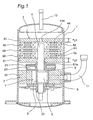
- Fig. 1 is a cross-sectional view of a compressor using an axial gap motor according to the first embodiment of the present invention.
- the compressor of the first embodiment is a high-pressure dome type with stators which are different from each other in inside diameter and back yoke thickness.
- the compressor of the first embodiment has, as shown in Fig. 1 , a closed container 1, a compression mechanism 2 located in the closed container 1, and an axial gap motor 3 which is located in the closed container and on the upper side of the compression mechanism 2 and drives the compression mechanism 2 through a rotating shaft 4.
- a suction pipe 11 is connected to the lower lateral side of the closed container 1, while a discharge pipe 12 is connected to the upper side of the closed container 1. Refrigerant gas supplied through the suction pipe 11 is guided to the suction side of the compression mechanism 2.
- the axial gap motor 3 has a rotor 50 fixed around the rotating shaft 4, a first stator 40 located on the axial upper side of the rotor 50, and a second stator 60 located on the axial lower side of the rotor 50.
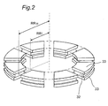
- the rotor 50 is made, as shown in Fig. 2 , in such a way that permanent magnets 32 are sandwiched between rotor cores 33 made of magnetic material (soft magnetic material such as iron) from both axial sides of the permanent magnets 32.
- the permanent magnets 32 having different magnetic poles are magnetically separated from each other including the rotor cores 33.
- RRo is the radius of a circle connecting outermost peripheries, relative to the rotating shaft 4, of the rotor cores 33
- RRi1 is the radius of a circle connecting innermost peripheries, relative to the rotating shaft 4, of the rotor cores 33.
- RRo is the radius of a circle connecting outermost peripheries, relative to the rotating shaft 4 (shown in Fig. 1 ), of the permanent magnates
- RRi1 is the radius of a circle connecting innermost peripheries, relative to the rotating shaft 4, of the permanent magnets.
- the permanent magnets 32 and the rotor cores 33 shown in Fig. 2 are molded in one piece as shown in Fig. 3 in order to hold the whole of the rotor 50.
- Fig. 3 shows an example molded entirely, but the rotor cores may be exposed from the resin to reduce the lengths of the air gaps. Since the permanent magnets 32 are used for the rotor 50, the magnetic flux densities of the air gaps can be increased and the torque can be thus improved. Furthermore, since the permanent magnets are provided in one layer axially, the quantity of magnets can be reduced. In addition, since the iron cores (rotor cores) are provided on the surfaces of the magnets, the rotor is resistant to demagnetization. If the rotor cores are dust iron cores, they also contribute to a reduction in eddy-current loss.
- the first stator 40 has a back yoke 41 made of a magnetic material shaped like a disk having a hole 41a in the center, and coils 42 wound around teeth 44 which are installed in a standing manner along a circumference on the back yoke 41.
- the second stator 60 has a back yoke 61 made of a magnetic material shaped like a disk having a shaft hole 61a in the center, and coils 62 wound around teeth 64 which are installed in a standing manner along a circumference on the back yoke 61.
- Fig. 4 is a perspective view of the second stator 60.
- the first stator 40 has a configuration similar to the second stator 60 (upside down) except that the diameter of the center hole is less than that of the second stator and the thickness of the back yoke is less than that of the second stator.
- the second stator 60 has axial coils directly wound around the teeth 64 extending axially.
- the teeth 64 are magnetically connected with each other by the back yoke 61.
- the coils 62 are connected, for example, in a star connection, to which an electric current is supplied from an inverter (ditto for the first stator 40).
- Coils 42 are wound around teeth in positions facing the rotor 50 of the first stator 40 so as to generate poles opposite to those generated by coils 62 wound around teeth in positions facing the rotor 50 of the second stator 50. In other words, coils wound around teeth in the same direction when viewed from one of axial directions are provided.
- Ro is the outside radius of the back yoke 61
- Rto2 is the radius of a circle connecting outermost peripheries, relative to the rotating shaft 4, of the teeth 64
- Rti2 is the radius of a circle connecting innermost peripheries, relative to the rotating shaft 4, of the teeth 64
- Ri2 is the inside radius of the back yoke 61.
- the compression mechanism 2 has, as shown in Fig. 1 , a cylinder-like main body 20, and a top end plate 8 and a bottom end plate 9 which are fitted to the upper open end and the lower open end of the main body 20, respectively.
- the rotating shaft 4 penetrates the top end plate 8 and the bottom end plate 9 and is inserted in the main body 20.
- the rotating shaft 4 is rotatably supported by a bearing 21 provided on the top end plate 8 of the compression mechanism 2 and a bearing 22 provided on the bottom end plate 9 of the compression mechanism 2.
- a crank pin 5 is provided on the rotating shaft 4 in the main body 20, and compression is conducted with a compression chamber 7 formed between a piston 6 which is engaged with and driven by the crank pin 5 and a cylinder corresponding to the piston 6.
- the piston 6 revolves in an eccentric state to change the capacity of the compression chamber 7.
- the bearing 21 is not provided only on the second stator 60 side rather than on the rotor 50 side, with an open-sided structure. Specifically, the bearing 21 is provided inside a portion having the discharge port 23 of the upper part of the compression mechanism 2, and may also be provided inside the second stator. Furthermore, the compression mechanism 2 is provided on the side opposite to the rotor 50 of the bearing 21.
- the radius of the hole 41a of the back yoke 41 of the first stator 40 is less than the radius of the shaft hole 61a of the back yoke 61 of the second stator 60. This is because it is not necessary for the rotating shaft 4 to extend to the first stator 40 and the shaft does not penetrate the first stator 40. Specifically, it is necessary for the shaft hole 61a of the second stator 60 to be larger than the rotating shaft 4 in diameter, but no shaft hole is necessary for the first stator 40. Furthermore, the tip of the rotating shaft 4 can be less than other portions in diameter, so that even if the shaft penetrates the first stator, the tip can be certainly less than the shaft hole of the second stator in diameter. However, in the case of a compressor, the first stator needs any refrigerant passage, thus needing any through-hole.
- Fig. 5 which is a perspective view of a first stator 140 having through-holes as refrigerant passages
- refrigerant passages may be provided also around the axis of a second stator.
- oil-return passages 141b are provided on the outer periphery.
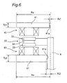
- Fig. 6 is a schematic diagram of a longitudinal section of the main part of the axial gap motor. Even if the thickness Ty1 of the back yoke 41 of the first stator 40 is made less than the thickness Ty2 of the back yoke 61 of the second stator 60 as shown in Fig. 6 , a certain magnetic path area can be secured because the back yoke 41 of the first stator 40 has an enough width.
- the reluctance of the first stator 40 can be made substantially equal to that of the second stator 60, so that the axial dimension of the motor can be reduced in a structure with the first stator 40 and the second stator 60 facing each other on both axial sides of the rotor 50.
- the radius of the hole 41a of the back yoke 41 is Ri1
- the radius of the shaft hole 61a of the back yoke 61 is Ri2
- the sectional area of the magnetic path of the first stator 40 is the same as that of the second stator 60.
- the axial thickness of a rotor can be reduced. In other words, in the rotor, magnetic flux axially penetrates it.
- the back yoke of the second stator needs sufficient strength because discharged gas from the compression mechanism directly acts on the back yoke of the second stator, but the back yoke of the first stator does not need much strength because the discharged gas acts on the back yoke of the first stator after the discharged gas has passed through the air gap, etc of the motor and the pulsation has been sufficiently attenuated.
- the thickness of the back yoke of the first stator is made less than that of the second stator.
- the second stator 60 has wide portions 65 on the tips of the teeth 64 as shown in Fig. 7 , the outside diameter and inside diameter of the wide portions 65 are read in a different way as the outside diameter and inside diameter of the teeth 64.
- the wide portions 65 on the tips of the teeth serve to allow the magnetic flux of the rotor 60 to more link with the second stator (ditto for the first stator).
- part of the wide portions 65 is cut so that part of the teeth 64 can be seen.
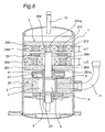
- Fig. 8 is a cross-sectional view of a compressor using an axial gap motor 303 according to the second embodiment of the present invention.
- the compressor of the second embodiment is a high-pressure dome type in which stators are different from each other in inside diameter and back yokes of the stators are different from each other in thickness.
- the relations between the inside diameters, outside diameters, and thicknesses of the back yokes are the same as those of the first embodiment.
- the same configuration as the compressor of the first embodiment is shown with the same reference numbers.
- a first stator 240 has a back yoke 241 made of magnetic material shaped like a disk having a hole 241a in the center, and coils 242 wound around teeth 244 which are installed in a standing manner along a circumference on the back yoke 241.
- a second stator 260 has a back yoke 261 made of magnetic material shaped like a disk having a shaft hole 261a in the center, and coils 262 wound around teeth 264 which are installed in a standing manner along a circumference on the back yoke 261.
- a thick rotating shaft 204 (needing at least a thickness for holding the rotor 50 to the bearing 21) passes through the shaft hole 261a of the second stator 260, so that a space capable of accommodating the coils 262 and teeth 264 of the second stator 260 is limited.
- a space capable of accommodating the coils 242 and teeth 244 of the first stator 240 is limited only by an end portion 204a of the rotating shaft 204 which is thinner than other portions of it.
- the teeth 244 of the first stator 240 can be provided inside more than the teeth of the second stator 260, and the radial width of the coils 242 of the first stator 240 can be made larger than that of the second stator 260. If the rotating shaft 204 does not protrude from the rotor 50 to the first stator, the radial width of the coils 242 can be made still larger.
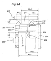
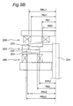
- Fig. 9A is a schematic diagram of a longitudinal section of the main part of the axial gap motor 303.
- the first stator 240 and the second stator 260 are similar to the second stator 60 shown in Fig. 4 , and the first stator 240 is different from the second stator 260 in positions of teeth, forms of coils, etc. As shown in Fig. 9A , assuming that:
- the coils 242 of the first stator 240 can be installed to the inner radius portion, so that the distance between the inner periphery of the compression container 1 and the teeth 244 is increased (Rto1 ⁇ Rto2) and the inside diameter of the teeth 244 is reduced accordingly (Rti1 ⁇ Rti2).
- the sectional area of the teeth 244 may be reduced. For this reason, if Rto ⁇ 1 - Rti ⁇ 1 > Rto ⁇ 2 - Rti ⁇ 2 is satisfied, the sectional area of the teeth of the first stator can be made substantially equal to the sectional area of the teeth of the second stator.
- the sectional area of the coils 242 of the first stator 240 becomes larger than that of the second stator 2560. If the height of the coils 242 is adjusted so that the sectional area of the coils 242 of the first stator 240 becomes equal to that of the second stator 260, the magnetomotive force of the first stator 240 preferably becomes equal to that of the second stator 260. Specifically, thrust force is more cancelled.
- Lc1 the axial length of the coils 242 of the first stator 240
- the axial length of the coils 262 of the second stator 260 is Lc2
- Lc ⁇ 1 ⁇ Lc ⁇ 2 is satisfied. For this reason, the axial length of the first stator is more reduced.
- the diameter of a portion facing the rotor 250 of the first stator 240 is different from that of the second stator 260.
- the area at portions facing the first stator 240 and the second stator 260 of the rotor 250 is reduced.
- the rotor cores 233 and 234 are provided on both sides of the permanent magnets 232.
- the diameter of the rotor cores 233 on the top end face of the rotor 250 and the diameter of the rotor cores 234 on the bottom face of the rotor 250 are shifted in agreement with the diameter of the teeth 244 of the first stator 240 and the diameter of the teeth 264 of the second stator 260, respectively.
- RRo1 is slightly larger than Rto1
- RRo2 is slightly larger than Rto2
- RRi1 is slightly less than Rti1
- RRi2 is slightly less than Rti2.
- the rotor cores 233 and 234 of the rotor 250 are designed to cover the tips of the teeth 244 and 264 of the first and second stators 240 and 260.
- Fig. 10A is a perspective view of the rotor 250 seen obliquely from above
- Fig. 10B is a perspective view of the rotor 250 turned upside down seen obliquely from above.
- a holding mold, etc are omitted.
- rotor cores 333 and 334 made of magnetic material having about the same sectional form as that of the permanent magnets 332 may be provided on both ends of permanent magnets 332 of a rotor 350.
- the teeth 244 and 264 of the first and second stators 240 and 260 are also included between the outside diameter and the inside diameter of the rotor cores 333 and 334.
- This configuration while allowing a large sectional area of the permanent magnets 332, allows magnetic flux to be concentrated on the tips of the teeth 244 and 264 by the rotor cores 333 and 334.
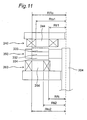
- permanent magnets 434 and 435 may be provided on both surfaces of a back yoke 433 of a rotor 450 so as to be exposed to the air gaps.
- the back yoke 433 short-circuits the opposite magnetic pole surfaces of the magnets facing each other axially rather than short-circuits the magnet poles of the magnets adjacent to each other circumferentially, and therefore does not need a much thickness.
- the outside diameter and inside diameter of the tips of the teeth 244 are matched to the outside diameter and inside diameter of the permanent magnets 434, and the outside diameter and inside diameter of the tips of the teeth 264 are matched to the outside diameter and inside diameter of the permanent magnets 435. Specifically, assuming that:
- the outside diameter and inside diameter of the teeth are read in a different way as the outside diameter and inside diameter of the wide portions.
- Fig. 13 shows the structure of a stator 360 as a variation of the first and second stators 240 and 260, in which teeth 364 are installed in a standing manner along a circumference on a back yoke 361 and a coil 362 is wound around each of the teeth 364.
- the wide portions 365 of the tips of the teeth 364 are connected and integrated by thin portions 365a on the inner peripheries and the outer peripheries.
- the radius of the outsides of the wide portions 365 is Rho and the radius of the insides of them is Rhi. Rho and Rhi may be defined except the thin portions 365a. In either case, the thin portions 365a are sufficiently thin to such an extent that magnetic flux is not easily saturated and thus not short-circuited, so that there is no big difference between both definitions.
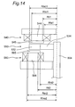
- Fig. 14 is a schematic diagram of a longitudinal section of the main part of another variation of the axial gap motor, in which both ends of permanent magnets 532 directly face air gaps.
- the permanent magnets 532 can be obtained by, for example, magnetizing a ring magnet in multiple poles.
- Inner periphery portions 534 of the permanent magnets 532 may be non-magnetic materials or non-magnetized portions of magnets.
- the inner periphery portions 534 serve to hold a rotating shaft 504.
- Wide portions 545 and 565 of the tips of teeth 544 and 564 of first and second stators 540 and 560 also include magnetic pole surfaces of permanent magnets. This is particularly effective in the case of a surface magnet type with magnetic pole surfaces of permanent magnets exposed to air gaps.
- Fig. 15 is a schematic diagram of a longitudinal section of the main part of another variation of the axial gap motor.
- wide portions 645 of an upper first stator 640 are the same as wide portions 665 of a lower second stator 660, and the wide portions 645 and 665 face straight permanent magnets 632 of a rotor 650 fixed to a rotating shaft 604.
- the wide portions 645 and 665 cover the total area of the tips of teeth 644 and 664.
- the wide portions 645 and 665 of the first and second stators 640 and 660 can be used in common.
- ribs 746 protruding axially may be provided on the back yoke 741 of the first stator 740, preferably on the air gap side of the first stator 740.
- the ribs 746 are each a combination of an arc-shaped rib 746a provided circumferentially and a linear rib 746b provided radially, but may be either of them.
- the linear ribs 746b provided radially are more effective when provided on portions having no tooth.
- Fig. 17 is an exploded perspective view of a motor according to the third embodiment of the present invention.
- This motor is a switched reluctance motor.
- a first stator 840 and a second stator 860 face each other through air gaps on both axial sides of a rotor 850 fixed on a rotating shaft 804.
- the rotating shaft 804 passes through a shaft hole 861a provided in a back yoke 861 of the second stator 860.
- the rotor 850 is shaped like a gear wheel with coupled inner periphery portions, and only a non-coupled portion of the rotor 850 faces the teeth 864 of the first and second stators 840 and 860.
- a coupled portion 852 of the rotor 850 mainly has a function of holding a gear portion 851 and fitting to the rotating shaft 804, and may act as a back yoke partially.
- main magnetic flux that is, magnetic flux coming from the teeth of the first stator 840 arrives at the teeth 864 of the second stator 860 through the gear portion 851.
- the coupled portion 852 is little useful as a back yoke.
- the first stator 840 is different from the second stator 860 only in the thickness of the back yoke 841, 861, but may be different from the second stator 860 in positions of teeth, etc. like the first and second embodiments.
Landscapes
- Engineering & Computer Science (AREA)
- Power Engineering (AREA)
- Mechanical Engineering (AREA)
- General Engineering & Computer Science (AREA)
- Iron Core Of Rotating Electric Machines (AREA)
- Connection Of Motors, Electrical Generators, Mechanical Devices, And The Like (AREA)
- Permanent Magnet Type Synchronous Machine (AREA)
- Compressor (AREA)
- Applications Or Details Of Rotary Compressors (AREA)
Applications Claiming Priority (2)
| Application Number | Priority Date | Filing Date | Title |
|---|---|---|---|
| JP2006252505A JP4816358B2 (ja) | 2006-09-19 | 2006-09-19 | モータおよび圧縮機 |
| PCT/JP2007/067741 WO2008035599A1 (fr) | 2006-09-19 | 2007-09-12 | Moteur et compresseur |
Publications (2)
| Publication Number | Publication Date |
|---|---|
| EP2066004A1 true EP2066004A1 (fr) | 2009-06-03 |
| EP2066004A4 EP2066004A4 (fr) | 2016-10-19 |
Family
ID=39200426
Family Applications (1)
| Application Number | Title | Priority Date | Filing Date |
|---|---|---|---|
| EP07807148.7A Withdrawn EP2066004A4 (fr) | 2006-09-19 | 2007-09-12 | Moteur et compresseur |
Country Status (7)
| Country | Link |
|---|---|
| US (1) | US8179016B2 (fr) |
| EP (1) | EP2066004A4 (fr) |
| JP (1) | JP4816358B2 (fr) |
| KR (1) | KR101025366B1 (fr) |
| CN (1) | CN101517860B (fr) |
| AU (1) | AU2007298344B2 (fr) |
| WO (1) | WO2008035599A1 (fr) |
Cited By (1)
| Publication number | Priority date | Publication date | Assignee | Title |
|---|---|---|---|---|
| EP2453549A1 (fr) * | 2010-11-12 | 2012-05-16 | Visedo Oy | Rotor à aimant permanent pour machine électrique à flux axial d'une machine de travail mobile |
Families Citing this family (48)
| Publication number | Priority date | Publication date | Assignee | Title |
|---|---|---|---|---|
| JP4816358B2 (ja) * | 2006-09-19 | 2011-11-16 | ダイキン工業株式会社 | モータおよび圧縮機 |
| US7847443B2 (en) * | 2008-04-10 | 2010-12-07 | Burgess-Norton Mfg. Co., Inc. | Manufacture of electric motor component |
| JP2010004635A (ja) * | 2008-06-19 | 2010-01-07 | Daikin Ind Ltd | 界磁子及びその製造方法並びに回転電機 |
| JP5359112B2 (ja) * | 2008-08-20 | 2013-12-04 | ダイキン工業株式会社 | アキシャルギャップ型回転電機及びそれを用いた圧縮機 |
| KR101217223B1 (ko) * | 2011-03-25 | 2012-12-31 | 주식회사 아모텍 | 비정질 분할코어 스테이터 및 이를 이용한 액시얼 갭형 모터 |
| JP5700217B2 (ja) * | 2011-07-28 | 2015-04-15 | 日本電産株式会社 | モータ |
| JP6001356B2 (ja) * | 2012-06-29 | 2016-10-05 | 株式会社ヴァレオジャパン | 電動圧縮機 |
| JP6103904B2 (ja) * | 2012-12-04 | 2017-03-29 | 株式会社ヴァレオジャパン | 電動圧縮機 |
| US10447102B2 (en) * | 2013-03-15 | 2019-10-15 | Regal Beloit Australia Pty. Ltd. | Permanent magnet electrical machines and methods of assembling the same |
| GB2519060B (en) * | 2013-08-08 | 2016-08-03 | Yasa Motors Ltd | Cooling of axial flux motors - centrifugal |
| US9543818B2 (en) * | 2013-09-15 | 2017-01-10 | The Boeing Company | Ferrofluid motor |
| WO2015083261A1 (fr) * | 2013-12-05 | 2015-06-11 | 三菱電機株式会社 | Compresseur |
| TWI514725B (zh) * | 2013-12-19 | 2015-12-21 | Delta Electronics Inc | 線性馬達及其適用之馬達組 |
| KR102201857B1 (ko) * | 2014-01-03 | 2021-01-12 | 삼성전자주식회사 | 밀폐형 압축기 |
| CN104481884B (zh) * | 2014-12-05 | 2017-11-10 | 广东美芝制冷设备有限公司 | 制冷系统及具有轴向磁通电机的旋转式压缩机 |
| CN104564685A (zh) * | 2015-01-06 | 2015-04-29 | 广东美芝制冷设备有限公司 | 旋转式压缩机及具有其的制冷装置 |
| CN111342632B (zh) | 2015-06-09 | 2022-05-10 | 三菱电机株式会社 | 压缩机用电动机、压缩机及制冷循环装置 |
| JP6151324B2 (ja) * | 2015-09-17 | 2017-06-21 | 三菱重工業株式会社 | 密閉型電動圧縮機 |
| US10326323B2 (en) | 2015-12-11 | 2019-06-18 | Whirlpool Corporation | Multi-component rotor for an electric motor of an appliance |
| WO2018008054A1 (fr) * | 2016-07-04 | 2018-01-11 | 株式会社日立産機システム | Compresseur à vis |
| US10704180B2 (en) | 2016-09-22 | 2020-07-07 | Whirlpool Corporation | Reinforcing cap for a tub rear wall of an appliance |
| JP2018061341A (ja) * | 2016-10-05 | 2018-04-12 | Ntn株式会社 | アキシャルギャップ型モータ |
| DE112017005600T5 (de) * | 2016-11-07 | 2019-09-12 | Denso Corporation | Anbringungsstruktur für einen Fahrzeugmotor, Ausstattung in einem Fahrzeug, und bürstenloser Motor |
| US10418889B2 (en) | 2017-01-31 | 2019-09-17 | Regal Beloit Australia Pty Ltd. | Modular stator for axial flux electric machines and methods of assembling the same |
| US10770940B2 (en) | 2017-01-31 | 2020-09-08 | Regal Beloit Australia Pty Ltd. | Modular rotors for axial flux electric machines |
| US10541591B2 (en) | 2017-01-31 | 2020-01-21 | Regal Beloit Australia Pty, Ltd. | Composite stator for axial flux electric machines and methods of assembling the same |
| US10320268B2 (en) | 2017-01-31 | 2019-06-11 | Regal Beloit Australia Pty Ltd | Modular stator drive units for axial flux electric machines |
| US10594180B2 (en) * | 2017-01-31 | 2020-03-17 | Regal Beloit America, Inc. | Magnetic flux guides for electric machines |
| US11111921B2 (en) | 2017-02-06 | 2021-09-07 | Emerson Climate Technologies, Inc. | Co-rotating compressor |
| US10995754B2 (en) | 2017-02-06 | 2021-05-04 | Emerson Climate Technologies, Inc. | Co-rotating compressor |
| US10465954B2 (en) | 2017-02-06 | 2019-11-05 | Emerson Climate Technologies, Inc. | Co-rotating compressor with multiple compression mechanisms and system having same |
| US10280922B2 (en) * | 2017-02-06 | 2019-05-07 | Emerson Climate Technologies, Inc. | Scroll compressor with axial flux motor |
| US10215174B2 (en) | 2017-02-06 | 2019-02-26 | Emerson Climate Technologies, Inc. | Co-rotating compressor with multiple compression mechanisms |
| US10693336B2 (en) | 2017-06-02 | 2020-06-23 | Whirlpool Corporation | Winding configuration electric motor |
| US11937410B2 (en) * | 2018-09-13 | 2024-03-19 | Hitachi Industrial Equipment Systems Co., Ltd. | Package-type fluid machine |
| JP7011616B2 (ja) * | 2019-02-26 | 2022-01-26 | 東芝三菱電機産業システム株式会社 | 同期回転電機 |
| KR102868717B1 (ko) | 2019-09-05 | 2025-10-02 | 마툴 홀딩스, 인크. | 자기 회전 결합 장치를 위한 시스템 및 방법 |
| CN114729637B (zh) | 2019-11-15 | 2024-07-02 | 谷轮有限合伙公司 | 共旋转的涡旋式压缩机 |
| JP7381386B2 (ja) * | 2020-04-01 | 2023-11-15 | 三菱重工サーマルシステムズ株式会社 | ロータリ圧縮機 |
| CN111828476B (zh) * | 2020-06-30 | 2021-06-04 | 珠海格力电器股份有限公司 | 定子铁芯、磁悬浮轴承及其支撑系统、控制方法、电机 |
| WO2022017014A1 (fr) * | 2020-07-20 | 2022-01-27 | 丹佛斯(天津)有限公司 | Stator destiné à être utilisé dans un moteur à cylindres opposés à plat, anneau support de stator, et compresseur |
| CN113364179B (zh) * | 2021-06-21 | 2023-03-14 | 上海盘毂动力科技股份有限公司 | 一种降低涡流损耗的转子 |
| CN113949177A (zh) * | 2021-09-22 | 2022-01-18 | 义乌吉利自动变速器有限公司 | 一种定转子结构和轴向磁场电机 |
| US11732713B2 (en) | 2021-11-05 | 2023-08-22 | Emerson Climate Technologies, Inc. | Co-rotating scroll compressor having synchronization mechanism |
| US11624366B1 (en) | 2021-11-05 | 2023-04-11 | Emerson Climate Technologies, Inc. | Co-rotating scroll compressor having first and second Oldham couplings |
| US12104594B2 (en) | 2021-11-05 | 2024-10-01 | Copeland Lp | Co-rotating compressor |
| WO2023125811A1 (fr) * | 2021-12-31 | 2023-07-06 | 丹佛斯(天津)有限公司 | Compresseur à spirale |
| DE102022106623A1 (de) | 2022-03-22 | 2023-09-28 | Schaeffler Technologies AG & Co. KG | Elektrische Axialflussmaschine, Antriebsmodul, Verfahren zur Herstellung einer elektrischen Axialflussmaschine |
Family Cites Families (37)
| Publication number | Priority date | Publication date | Assignee | Title |
|---|---|---|---|---|
| US2824275A (en) * | 1956-06-29 | 1958-02-18 | Kober William | Electric generator and regulator |
| JPS56115166A (en) * | 1980-02-18 | 1981-09-10 | Ouken Seikou Kk | Coreless motor and manufacture of coil thereof |
| SU1119124A1 (ru) * | 1980-03-07 | 1984-10-15 | Ленинградское Электромашиностроительное Объединение "Электросила" Им.С.М.Кирова | Статор электрической машины |
| JPS62173961A (ja) * | 1986-01-27 | 1987-07-30 | Fanuc Ltd | デイスク型永久磁石式同期電動機 |
| US5168187A (en) * | 1991-02-20 | 1992-12-01 | Dana Corporation, Warner Electric Brake & Clutch Division | Axial pole stepping motor |
| JPH07336967A (ja) * | 1994-06-03 | 1995-12-22 | Yaskawa Electric Corp | 軸方向空隙形同期モータ |
| JP3177177B2 (ja) * | 1996-12-10 | 2001-06-18 | 日東造機株式会社 | 扁平モータ |
| US6411002B1 (en) * | 1996-12-11 | 2002-06-25 | Smith Technology Development | Axial field electric machine |
| US6348751B1 (en) * | 1997-12-12 | 2002-02-19 | New Generation Motors Corporation | Electric motor with active hysteresis-based control of winding currents and/or having an efficient stator winding arrangement and/or adjustable air gap |
| DE69930643T2 (de) * | 1999-01-14 | 2006-08-17 | Kabushiki Kaisha Yaskawa Denki, Kitakyushu | Impulsgeber mit flächiger spule |
| US6445105B1 (en) * | 1999-04-06 | 2002-09-03 | General Electric Company | Axial flux machine and method of fabrication |
| US6605883B2 (en) * | 2001-04-20 | 2003-08-12 | Japan Servo Co., Ltd. | Multi-phase flat-type PM stepping motor and driving circuit thereof |
| JP3561248B2 (ja) * | 2001-09-17 | 2004-09-02 | 日本サーボ株式会社 | 偏平多相永久磁石形ステッピングモータとその励磁回路 |
| FR2830136B1 (fr) * | 2001-09-25 | 2004-09-03 | Moving Magnet Tech | Moteur polyphase a deux ou trois phases |
| US6717324B2 (en) * | 2001-10-15 | 2004-04-06 | Ming Yan Chen | Magnet motor device |
| US6922004B2 (en) * | 2002-04-05 | 2005-07-26 | The Timken Company | Axial flux motor assembly |
| US20050140231A1 (en) * | 2002-05-01 | 2005-06-30 | Makoto Ogoshi | Power generator and torque amplifier |
| JP4003058B2 (ja) * | 2002-07-17 | 2007-11-07 | 株式会社富士通ゼネラル | 誘導電動機 |
| US6995494B2 (en) * | 2002-10-14 | 2006-02-07 | Deere & Company | Axial gap brushless DC motor |
| US7034427B2 (en) * | 2003-08-18 | 2006-04-25 | Light Engineering, Inc. | Selective alignment of stators in axial airgap electric devices comprising low-loss materials |
| KR100786433B1 (ko) * | 2003-10-09 | 2007-12-17 | 마쯔시다덴기산교 가부시키가이샤 | Ac전원에 직결된 브러시리스 dc모터와 그 모터를이용한 전기 장치 |
| US7190101B2 (en) * | 2003-11-03 | 2007-03-13 | Light Engineering, Inc. | Stator coil arrangement for an axial airgap electric device including low-loss materials |
| US6977454B2 (en) * | 2003-11-12 | 2005-12-20 | Ut-Battelle Llc | Hybrid-secondary uncluttered permanent magnet machine and method |
| JP4193685B2 (ja) * | 2003-12-15 | 2008-12-10 | 日産自動車株式会社 | アキシャルギャップモータ構造 |
| JP2005257240A (ja) * | 2004-03-15 | 2005-09-22 | Sanyo Electric Co Ltd | 遷臨界冷凍装置 |
| DE102004014865A1 (de) * | 2004-03-26 | 2005-10-13 | Ina-Schaeffler Kg | Elektrischer Nockenwellerversteller mit Scheibenläufermotor |
| US7608964B2 (en) * | 2004-03-31 | 2009-10-27 | Daikin Industries, Ltd. | Motor, blower, compressor, and air conditioner |
| JP2005318782A (ja) * | 2004-03-31 | 2005-11-10 | Nissan Motor Co Ltd | アキシャルギャップ電動機の冷却構造 |
| JP4432616B2 (ja) * | 2004-05-26 | 2010-03-17 | 日産自動車株式会社 | アキシャルギャップ型回転電機 |
| KR100580524B1 (ko) * | 2004-07-16 | 2006-05-15 | 현대자동차주식회사 | 축향자속전기모터 |
| JP2006081364A (ja) * | 2004-09-13 | 2006-03-23 | Moric Co Ltd | ブラシ付きフラットモータ |
| JP2006166679A (ja) * | 2004-12-10 | 2006-06-22 | Nissan Motor Co Ltd | アキシャルギャップ型回転電機のステータ構造 |
| JP4586599B2 (ja) * | 2005-03-25 | 2010-11-24 | ダイキン工業株式会社 | 圧縮機 |
| EP1717935A2 (fr) * | 2005-04-28 | 2006-11-02 | LuK Lamellen und Kupplungsbau Beteiligungs KG | Machine électrique |
| JP2006353078A (ja) * | 2005-05-17 | 2006-12-28 | Nissan Motor Co Ltd | アキシャルギャップ型回転電機 |
| US7888904B2 (en) * | 2006-01-26 | 2011-02-15 | The Timken Company | Virtual moving air gap for an axial flux permanent magnet motor with dual stators |
| JP4816358B2 (ja) * | 2006-09-19 | 2011-11-16 | ダイキン工業株式会社 | モータおよび圧縮機 |
-
2006
- 2006-09-19 JP JP2006252505A patent/JP4816358B2/ja not_active Expired - Fee Related
-
2007
- 2007-09-12 KR KR1020087031945A patent/KR101025366B1/ko not_active Expired - Fee Related
- 2007-09-12 CN CN2007800338891A patent/CN101517860B/zh not_active Expired - Fee Related
- 2007-09-12 AU AU2007298344A patent/AU2007298344B2/en not_active Ceased
- 2007-09-12 WO PCT/JP2007/067741 patent/WO2008035599A1/fr not_active Ceased
- 2007-09-12 EP EP07807148.7A patent/EP2066004A4/fr not_active Withdrawn
- 2007-09-12 US US12/440,999 patent/US8179016B2/en not_active Expired - Fee Related
Non-Patent Citations (1)
| Title |
|---|
| See references of WO2008035599A1 * |
Cited By (1)
| Publication number | Priority date | Publication date | Assignee | Title |
|---|---|---|---|---|
| EP2453549A1 (fr) * | 2010-11-12 | 2012-05-16 | Visedo Oy | Rotor à aimant permanent pour machine électrique à flux axial d'une machine de travail mobile |
Also Published As
| Publication number | Publication date |
|---|---|
| JP4816358B2 (ja) | 2011-11-16 |
| WO2008035599A1 (fr) | 2008-03-27 |
| EP2066004A4 (fr) | 2016-10-19 |
| JP2008079362A (ja) | 2008-04-03 |
| CN101517860A (zh) | 2009-08-26 |
| KR101025366B1 (ko) | 2011-03-28 |
| KR20090027686A (ko) | 2009-03-17 |
| CN101517860B (zh) | 2011-09-21 |
| US20090230811A1 (en) | 2009-09-17 |
| US8179016B2 (en) | 2012-05-15 |
| AU2007298344B2 (en) | 2010-09-30 |
| AU2007298344A1 (en) | 2008-03-27 |
Similar Documents
| Publication | Publication Date | Title |
|---|---|---|
| AU2007298344B2 (en) | Motor and compressor | |
| KR100492238B1 (ko) | 전동기의 회전자 | |
| AU2008336853B2 (en) | Armature core, armature, rotary electric machine and compressor | |
| KR100440537B1 (ko) | 영구자석형 모터 및 영구자석형 모터의 제조방법 | |
| JP6055189B2 (ja) | 永久磁石式回転電機 | |
| US8410655B2 (en) | Stator, motor, and compressor | |
| JP2008029095A (ja) | 永久磁石式回転電機及びそれを用いた圧縮機 | |
| WO2016203563A1 (fr) | Moteur électrique de type à aimant permanent incorporé pour compresseur, compresseur, et dispositif à cycle de réfrigération | |
| US20180209330A1 (en) | Electric supercharger | |
| EP1701428A1 (fr) | Moteur | |
| JP2010051075A (ja) | アキシャルギャップ型回転電機及びそれを用いた圧縮機 | |
| JP4586599B2 (ja) | 圧縮機 | |
| JPH09200982A (ja) | ブラシレスdcモータの回転子及びその磁石位置決め固定方法 | |
| CN101803156B (zh) | 轴向间隙型旋转电机 | |
| JP2010041852A (ja) | 固定子、モータ、及び圧縮機 | |
| JP3689957B2 (ja) | 永久磁石型dcモータ | |
| JP2006211826A (ja) | 埋め込み磁石型ロータ | |
| JP2007321703A (ja) | 圧縮機 | |
| JP4618050B2 (ja) | 圧縮機 | |
| JPH09182332A (ja) | ブラシレスdcモータ | |
| JP2013051841A (ja) | 回転電気機械 | |
| JP3635485B2 (ja) | 永久磁石型電動機とその着磁方法 | |
| JPH11122853A (ja) | 圧縮機用電動機の回転子 | |
| JP2016029876A (ja) | 電動機の回転子、電動機、および電動機を備えた圧縮機 | |
| KR102515118B1 (ko) | 매립형 영구자석 전동기용 로터 |
Legal Events
| Date | Code | Title | Description |
|---|---|---|---|
| PUAI | Public reference made under article 153(3) epc to a published international application that has entered the european phase |
Free format text: ORIGINAL CODE: 0009012 |
|
| 17P | Request for examination filed |
Effective date: 20090310 |
|
| AK | Designated contracting states |
Kind code of ref document: A1 Designated state(s): AT BE BG CH CY CZ DE DK EE ES FI FR GB GR HU IE IS IT LI LT LU LV MC MT NL PL PT RO SE SI SK TR |
|
| AX | Request for extension of the european patent |
Extension state: AL BA HR MK RS |
|
| DAX | Request for extension of the european patent (deleted) | ||
| RA4 | Supplementary search report drawn up and despatched (corrected) |
Effective date: 20160920 |
|
| RIC1 | Information provided on ipc code assigned before grant |
Ipc: H02K 1/27 20060101ALI20160912BHEP Ipc: F04C 18/356 20060101ALI20160912BHEP Ipc: F04C 23/00 20060101ALI20160912BHEP Ipc: F04B 39/00 20060101ALI20160912BHEP Ipc: H02K 7/14 20060101ALI20160912BHEP Ipc: H02K 1/28 20060101ALI20160912BHEP Ipc: H02K 21/24 20060101ALI20160912BHEP Ipc: H02K 1/22 20060101ALI20160912BHEP Ipc: F04C 29/00 20060101ALI20160912BHEP Ipc: H02K 1/12 20060101AFI20160912BHEP |
|
| STAA | Information on the status of an ep patent application or granted ep patent |
Free format text: STATUS: REQUEST FOR EXAMINATION WAS MADE |
|
| STAA | Information on the status of an ep patent application or granted ep patent |
Free format text: STATUS: THE APPLICATION IS DEEMED TO BE WITHDRAWN |
|
| 18D | Application deemed to be withdrawn |
Effective date: 20170421 |