EP2066065A1 - Circuit d'émission de signal de commutation de canal et procédé d'émission de signal de commutation de canal - Google Patents
Circuit d'émission de signal de commutation de canal et procédé d'émission de signal de commutation de canal Download PDFInfo
- Publication number
- EP2066065A1 EP2066065A1 EP07828304A EP07828304A EP2066065A1 EP 2066065 A1 EP2066065 A1 EP 2066065A1 EP 07828304 A EP07828304 A EP 07828304A EP 07828304 A EP07828304 A EP 07828304A EP 2066065 A1 EP2066065 A1 EP 2066065A1
- Authority
- EP
- European Patent Office
- Prior art keywords
- channel switching
- iterative decoding
- decoding count
- signal
- switching condition
- Prior art date
- Legal status (The legal status is an assumption and is not a legal conclusion. Google has not performed a legal analysis and makes no representation as to the accuracy of the status listed.)
- Withdrawn
Links
- 238000000034 method Methods 0.000 title claims abstract description 40
- 238000004891 communication Methods 0.000 claims abstract description 24
- 238000012937 correction Methods 0.000 abstract description 88
- 238000012935 Averaging Methods 0.000 abstract description 27
- 230000008569 process Effects 0.000 abstract description 25
- 208000011580 syndromic disease Diseases 0.000 description 31
- 238000012545 processing Methods 0.000 description 9
- 238000010586 diagram Methods 0.000 description 8
- 230000005540 biological transmission Effects 0.000 description 5
- 238000007796 conventional method Methods 0.000 description 2
- 230000006866 deterioration Effects 0.000 description 2
- 230000007246 mechanism Effects 0.000 description 2
- 230000003213 activating effect Effects 0.000 description 1
- 230000004913 activation Effects 0.000 description 1
- 230000008901 benefit Effects 0.000 description 1
- 230000007423 decrease Effects 0.000 description 1
- 230000003247 decreasing effect Effects 0.000 description 1
- 230000000694 effects Effects 0.000 description 1
- 238000005259 measurement Methods 0.000 description 1
- 238000012544 monitoring process Methods 0.000 description 1
Images


Classifications
-
- B—PERFORMING OPERATIONS; TRANSPORTING
- B23—MACHINE TOOLS; METAL-WORKING NOT OTHERWISE PROVIDED FOR
- B23B—TURNING; BORING
- B23B5/00—Turning-machines or devices specially adapted for particular work; Accessories specially adapted therefor
- B23B5/16—Turning-machines or devices specially adapted for particular work; Accessories specially adapted therefor for bevelling, chamfering, or deburring the ends of bars or tubes
- B23B5/166—Devices for working electrodes
-
- H—ELECTRICITY
- H03—ELECTRONIC CIRCUITRY
- H03M—CODING; DECODING; CODE CONVERSION IN GENERAL
- H03M13/00—Coding, decoding or code conversion, for error detection or error correction; Coding theory basic assumptions; Coding bounds; Error probability evaluation methods; Channel models; Simulation or testing of codes
- H03M13/03—Error detection or forward error correction by redundancy in data representation, i.e. code words containing more digits than the source words
- H03M13/05—Error detection or forward error correction by redundancy in data representation, i.e. code words containing more digits than the source words using block codes, i.e. a predetermined number of check bits joined to a predetermined number of information bits
- H03M13/11—Error detection or forward error correction by redundancy in data representation, i.e. code words containing more digits than the source words using block codes, i.e. a predetermined number of check bits joined to a predetermined number of information bits using multiple parity bits
- H03M13/1102—Codes on graphs and decoding on graphs, e.g. low-density parity check [LDPC] codes
- H03M13/1105—Decoding
- H03M13/1128—Judging correct decoding and iterative stopping criteria other than syndrome check and upper limit for decoding iterations
-
- H—ELECTRICITY
- H03—ELECTRONIC CIRCUITRY
- H03M—CODING; DECODING; CODE CONVERSION IN GENERAL
- H03M13/00—Coding, decoding or code conversion, for error detection or error correction; Coding theory basic assumptions; Coding bounds; Error probability evaluation methods; Channel models; Simulation or testing of codes
- H03M13/29—Coding, decoding or code conversion, for error detection or error correction; Coding theory basic assumptions; Coding bounds; Error probability evaluation methods; Channel models; Simulation or testing of codes combining two or more codes or code structures, e.g. product codes, generalised product codes, concatenated codes, inner and outer codes
- H03M13/2957—Turbo codes and decoding
- H03M13/2975—Judging correct decoding, e.g. iteration stopping criteria
-
- H—ELECTRICITY
- H03—ELECTRONIC CIRCUITRY
- H03M—CODING; DECODING; CODE CONVERSION IN GENERAL
- H03M13/00—Coding, decoding or code conversion, for error detection or error correction; Coding theory basic assumptions; Coding bounds; Error probability evaluation methods; Channel models; Simulation or testing of codes
- H03M13/35—Unequal or adaptive error protection, e.g. by providing a different level of protection according to significance of source information or by adapting the coding according to the change of transmission channel characteristics
- H03M13/353—Adaptation to the channel
-
- H—ELECTRICITY
- H03—ELECTRONIC CIRCUITRY
- H03M—CODING; DECODING; CODE CONVERSION IN GENERAL
- H03M13/00—Coding, decoding or code conversion, for error detection or error correction; Coding theory basic assumptions; Coding bounds; Error probability evaluation methods; Channel models; Simulation or testing of codes
- H03M13/63—Joint error correction and other techniques
- H03M13/6337—Error control coding in combination with channel estimation
-
- Y—GENERAL TAGGING OF NEW TECHNOLOGICAL DEVELOPMENTS; GENERAL TAGGING OF CROSS-SECTIONAL TECHNOLOGIES SPANNING OVER SEVERAL SECTIONS OF THE IPC; TECHNICAL SUBJECTS COVERED BY FORMER USPC CROSS-REFERENCE ART COLLECTIONS [XRACs] AND DIGESTS
- Y10—TECHNICAL SUBJECTS COVERED BY FORMER USPC
- Y10T—TECHNICAL SUBJECTS COVERED BY FORMER US CLASSIFICATION
- Y10T29/00—Metal working
- Y10T29/49—Method of mechanical manufacture
- Y10T29/49718—Repairing
- Y10T29/49748—Repairing by shaping, e.g., bending, extruding, turning, etc.
-
- Y—GENERAL TAGGING OF NEW TECHNOLOGICAL DEVELOPMENTS; GENERAL TAGGING OF CROSS-SECTIONAL TECHNOLOGIES SPANNING OVER SEVERAL SECTIONS OF THE IPC; TECHNICAL SUBJECTS COVERED BY FORMER USPC CROSS-REFERENCE ART COLLECTIONS [XRACs] AND DIGESTS
- Y10—TECHNICAL SUBJECTS COVERED BY FORMER USPC
- Y10T—TECHNICAL SUBJECTS COVERED BY FORMER US CLASSIFICATION
- Y10T29/00—Metal working
- Y10T29/51—Plural diverse manufacturing apparatus including means for metal shaping or assembling
-
- Y—GENERAL TAGGING OF NEW TECHNOLOGICAL DEVELOPMENTS; GENERAL TAGGING OF CROSS-SECTIONAL TECHNOLOGIES SPANNING OVER SEVERAL SECTIONS OF THE IPC; TECHNICAL SUBJECTS COVERED BY FORMER USPC CROSS-REFERENCE ART COLLECTIONS [XRACs] AND DIGESTS
- Y10—TECHNICAL SUBJECTS COVERED BY FORMER USPC
- Y10T—TECHNICAL SUBJECTS COVERED BY FORMER US CLASSIFICATION
- Y10T409/00—Gear cutting, milling, or planing
- Y10T409/30—Milling
- Y10T409/3042—Means to remove scale or raised surface imperfection
- Y10T409/304256—Means to remove flash or burr
Definitions
- the present invention relates to a channel switching signal generating circuit and channel switching signal generating method of outputting a channel switching signal of a wireless communication system using an error correction code by which a highly coding gain is obtained by iterative decoding and, more particularly, to a channel switching signal generating circuit and channel switching signal generating method of estimating the error rate of a transmission channel and outputting a switch signal, on the basis of information of an iterative decoding count required before the number of error bits output from an error correction decoder becomes 0.
- the coding gain (a C/N difference before and after error correction that achieves a necessary bit error rate (BER)) of the forward error correction (FEC) method applied to wireless communication systems is desirably high. Therefore, wireless communication systems are beginning to adopt highly coding gain codes (e.g., a turbo (convolutional) code, turbo product code (TPC), and LDPC code) that have been extensively studied in recent years. Since these highly coding gain codes are adopted, systems can be used at a C/N lower than that when using the RS (Reed-Solomon) code as a representative code adopted in the conventional systems. Another feature of these highly coding gain codes is that the code length is longer than those of codes such as the RS code in order to increase the coding gain.
- highly coding gain codes e.g., a turbo (convolutional) code, turbo product code (TPC), and LDPC code
- the reception level of a wireless communication system fluctuates in accordance with the status of a transmission channel.
- a protection channel is formed for an important channel, and the regular channel is switched to the protection channel by using a channel switching apparatus if the condition of the regular channel deteriorates.
- Japanese Patent Publication No. 8-4257 (reference 1) describes a channel switching apparatus capable of well following the quality deterioration speed of a propagation channel by monitoring the channel quality before error correction even in a system having an error correcting function.
- An error correction code used in the conventional wireless communication systems is generally a linear block code (e.g., the RS code or BCH code) to be decoded on the basis of the bounded distance decoding method using a hard-decision signal alone.
- a decoder executes decoding only once for each code block.
- the decoder outputs a syndrome signal indicating the presence/absence of errors in a transmitted block, and an error bit correction signal to be used when correcting error bits.
- the error rate information of the transmission channel can be obtained on the basis of the occurrence probability (i.e., the number of times of occurrence within a predetermined time) of these signals (the syndrome signal and error bit correction signal).
- the regular channel and protection channel are switched on the basis of this error rate information.
- the coding gain of the linear block code as described above is not so high, a state in which the BER after error correction is about 1 ⁇ 10 -6 can be detected on the basis of the syndrome signal or error bit correction signal.
- channel switching is performed when the channel quality matches a predetermined condition.
- channel switching is executed when the BER has exceeded a predetermined value (e.g., 1 ⁇ 10 -6 ).
- a predetermined value e.g. 1 ⁇ 10 -6 .
- a system in operation cannot directly measure the BER.
- the syndrome signal or error bit correction signal as the error rate information output by an error correction decoder during the operating process is observed for a predetermined time, and the BER is estimated by the number of observed signals.
- the syndrome signal takes a value 0 if there are no errors bit in a code block, and a value 1 if there is even one bit error.
- the conventional method such as the RS code detects the positions and bit patterns of errors from a decoding operation result corresponding to a hard-decision signal, and executes error correction by inverting a decoder input signal.
- the signal for bit inversion is an error bit correction signal. That is, when error correction is correctly executed, the error bit correction signal is a pulse signal corresponding to the number of bits of the errors.
- the code length is n bits
- the BER before correction equivalent to the BER of the switching condition after correction is p.
- the occurrence probability of the syndrome signal can be obtained by calculating the probability of the occurrence of an error having one bit or more in the n bits from p. By detecting a state equal to this syndrome signal occurrence probability, a switch signal can be output when the BER of the switching condition is detected. Note that even when using the error bit correction signal as the information source (error rate information), a switch signal can be output by performing control in accordance with the same concept as above.
- Fig. 11 is a block diagram showing an example of the arrangement of the channel switching signal generating circuit used in the wireless communication system.
- the channel switching signal generating circuit includes a decoder 904, counter 905, and comparator 903.
- the counter 905 receives a syndrome signal or error bit correction signal ("an error correction control bit" in reference 1) output from the decoder 904. Also, the counter 905 counts the input signals (syndrome signals or error bit correction signals) within a set observation period. The counter 905 then outputs the input signal count result to the comparator 903. The comparator 903 compares a threshold value with the output (count result) from the counter 905, and outputs a switch signal.
- the channel switching method shown in Fig. 11 is applied when using a highly coding gain code (e.g., the LDPC code) that undergoes iterative decoding (a decoding process is repetitively executed for one code block) by using a soft-decision signal, it is impossible to achieve switching at a BER of about 1 ⁇ 10 -6 that is appropriate when using the syndrome signal. Also, if this method is applied when using the error bit correction signal, it is necessary to add circuits unnecessary for the original decoding operation.
- a highly coding gain code e.g., the LDPC code
- iterative decoding a decoding process is repetitively executed for one code block
- the first problem is that even when the method is directly applied to a highly coding gain code, the syndrome signal cannot be used in the determination of a channel switching condition.
- a highly coding gain code such as the LDPC code
- a highly coding gain raises the BER before correction as an object of observation.
- the code length is long, the probability of the occurrence of error bits in one code word is higher than that of a code having a short code length for the same BER. Accordingly, even when the BER is lower than the switching condition, the syndrome signal occurrence probability is almost 100%. This makes it impossible to determine the switching condition by using the syndrome signal, so the syndrome signal cannot be used as an information source for switching.
- Fig. 12 is a graph showing the syndrome signal occurrence probability. Referring to Fig. 12 , the abscissa indicates the BER before correction, and the ordinate indicates the syndrome signal occurrence probability. A curve 201 shows the characteristic when using the LDPC code as a highly coding gain code. A curve 202 shows the characteristic when using the RS code.
- the second problem is that when using the error bit correction signal, a decoder requires an additional circuit in order to output the error bit correction signal.
- An PS-code decoder detects the bit positions of errors, and corrects the error bits by inverting bits in the detected positions.
- an iterative decoding type decoder performs signal processing of updating a signal to a more certain signal by repeating decoding. To output error bit information, therefore, it is necessary to successively compare the MSB (Most Significant Bit) of the log likelihood ratio (LLR) as input information to the decoder and an uncorrected signal with an output signal as the decoding result.
- MSB Most Significant Bit
- LLR log likelihood ratio
- an object of the present invention to provide a channel switching signal generating circuit and channel switching signal generating method capable of outputting a channel switching signal under appropriate conditions without increasing the number of circuits in a wireless communication system using a highly coding gain code (e.g., the LDPC code) to be iteratively decoded.
- a highly coding gain code e.g., the LDPC code
- a channel switching signal generating circuit comprises iterative decoding count output means for outputting an iterative decoding count indicating the number of times of iterative execution of a predetermined error correcting operation, channel switching condition determining means for determining whether a channel switching condition is met, on the basis of the iterative decoding count output from the iterative decoding count output means, and switch signal output means for outputting a switch signal indicating channel switching, when the channel switching condition determining means determines that the channel switching condition is met.
- a channel switching signal generating method comprises the steps of outputting an iterative decoding count indicating the number of times of iterative execution of a predetermined error correcting operation, determining whether a channel switching condition is met, on the basis of the iterative decoding count, and outputting a switch signal indicating channel switching, when it is determined that the channel switching condition is met.
- a switch signal is output by determining whether a channel switching condition is met, on the basis of the iterative decoding count of an error correcting operation. Accordingly, in a wireless communication system using a highly coding gain code to be iteratively decoded, a channel switching signal can be output under appropriate conditions without increasing the number of circuits.
- Fig. 1 is a block diagram showing an example of the arrangement of the receiving-side major components of a microwave communication system using a channel switching signal generating circuit according to the present invention.
- This microwave wireless communication system uses a highly coding gain code (e.g., the LDPC code) to be iteratively decoded.
- the microwave wireless communication system includes at least an antenna 401, receivers 402 and 412, demodulators 403 and 413, error correction decoders (DEC) 101 and 414, a channel switching circuit (SW) 405, an averaging circuit (AVE) 102, and a comparator (COMP) 103.
- DEC error correction decoders
- SW channel switching circuit
- AVE averaging circuit
- COMP comparator
- the receiver 402, demodulator 403, and error correction decoder 101 are devices for the regular channel, and the receiver 412, demodulator 413, and error correction decoder 414 are devices for a protection channel.
- the channel switching circuit 405 is a switch that switches the regular channel to the protection channel on the basis a channel switching signal.
- the error correction decoder 101, averaging circuit 102, and comparator 103 form a channel switching signal generating circuit 406 that outputs the channel switching signal to the channel switching circuit 405.
- a channel switching apparatus 407 is implemented by, e.g., a transmitting apparatus incorporating the channel switching signal generating circuit 406 and channel switching circuit 405.
- Fig. 2 is a block diagram showing an example of the arrangement of the channel switching signal generating circuit according to the present invention.
- the channel switching signal generating circuit 406 includes the error correction decoder 101, averaging circuit 102, and comparator 103.
- the error correction decoder 101 has a function of receiving a demodulation result (demodulated signal) as an output from the demodulator 403.
- the error correction decoder 101 also has a function of outputting a decoding result (decoded signal) by iteratively executing a predetermined error correcting operation.
- the error correction decoder 101 has a function of counting the number of times of iterative decoding executed during the process of the predetermined error correcting operation, and outputting the iterative decoding count to the averaging circuit 102.
- the error correction decoder 101 successively measures the iterative decoding count and outputs it to the averaging circuit 102 whenever executing the processing of the predetermined error correcting operation.
- the averaging circuit (average value calculator) 102 has a function of receiving the iterative decoding count from the error correction decoder 101. That is, the averaging circuit 102 successively receives the iterative decoding count whenever the error correction decoder 101 executes the processing of the predetermined error correcting operation.
- a predetermined value indicating the number of times of inputting of the iterative decoding count is preset in the averaging circuit 102.
- the averaging circuit 102 has a function of calculating the average value of the iterative decoding counts equal to the number of times indicated by the preset value, whenever receiving the iterative decoding counts equal to the number of times indicated by the preset value.
- the averaging circuit 102 also has a function of outputting the calculated average value of the iterative decoding counts to the comparator 103.
- a predetermined threshold value is preset in the comparator 103.
- the comparator 103 has a function of estimating the BER, when receiving the average value of the iterative decoding counts from the averaging circuit 102, by comparing the preset threshold value with the average value of the iterative decoding counts. More specifically, if the average value of the iterative decoding counts exceeds the threshold value, the comparator 103 determines that the channel switching condition is met, and outputs a switch signal for controlling channel switching to the channel switching circuit 405.
- the channel switching circuit 405 is incorporated in, e.g., the channel switching apparatus incorporating the channel switching signal generating circuit 406.
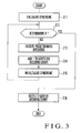
- Fig. 3 is a flowchart showing an example of processing executed by the error correction decoder 101.
- the error correction decoder 101 receives information corresponding to the signal certainty called a log likelihood ratio (LLR).
- LLR log likelihood ratio
- the MSB Most Significant Bit
- the error correction decoder 101 first calculates a syndrome (step S11).
- step S12 If the calculated syndrome is 0 (Y in step S12), then there are no bit errors, so the error correction decoder 101 immediately completes the decoding process. That is, the error correction decoder 101 completes the process in the first iterative decoding. In this case, the error correction decoder 101 terminates the process without ever executing a predetermined decoding process, and outputs an iterative decoding count 0 (step S16).
- step S12 If the calculated syndrome is not 0 (N in step S12), then there are bit errors, so the error correction decoder 101 executes a predetermined decoding operation once (step S13). As a result of this decoding operation, the certainty of the signal rises, and the number of bit errors in the decoded data decreases.
- the error correction decoder 101 adds 1 to the iterative decoding count (step S14), and recalculates the syndrome by performing the syndrome calculating operation (step S15). Then, the process returns to step S12.
- step S12 If the recalculated syndrome is 0 (Y in step S12), the error correction decoder 101 completes the decoding process, and outputs the current iterative decoding count (step S16).
- step S12 If the recalculated syndrome is not 0 (N in step S12), the process advances to step S13. After that, the error correction decoder 101 iteratively executes the above procedure (the processes in steps S12 to S15) until the syndrome becomes 0. When the syndrome has become 0, the error correction decoder 101 outputs the current iterative decoding count (step S16), and terminates the process.
- the iterative decoding count required before the number of bit errors becomes 0 varies because the number of local errors such as errors in a code block fluctuates from time to time.
- the decoding counts need only be averaged.
- the number of times of addition is the power of two, a circuit for performing the division can be implemented by bit shift, so the averaging circuit 102 can be implemented by a small circuit scale. Note that no averaging process is necessary when outputting a switch signal by using "when the maximum value of the decoding counts has exceeded a threshold value" as the switching condition.
- the set value of the number of times to be averaged must be balanced with the required accuracy of the BER estimated value.
- Fig. 4 is a flowchart showing an example of processing by which the channel switching signal generating circuit 406 outputs a switch signal.
- the averaging circuit 102 of the channel switching signal generating circuit 406 calculates the average value of the iterative decoding counts input from the error correction decoder 101 (step S21). That is, when receiving, e.g., iterative decoding counts equal to the number of times indicated by a preset value from the error correction decoder 101, the averaging circuit 102 calculates the average value of the iterative decoding counts equal to the number of times indicated by the set value. Then, the averaging circuit 102 outputs the calculated average value of the iterative decoding counts to the comparator 103.
- the comparator 103 compares the decoding count average value as an output from the averaging circuit 102 with a predetermined threshold value. The comparator 103 determines whether the decoding count average value is larger than the predetermined threshold value (step S22). If the decoding count average value exceeds the predetermined threshold value, the comparator 103 determines that the channel switching condition is met, and outputs a switch signal to the channel switching circuit 405 (step S23).
- the channel switching circuit 405 controls switching from the regular channel to the protection channel. That is, the channel switching circuit 405 switches the output signal from a signal of a device of the regular channel to a signal of a device of the protection channel.
- the decoding count average value is smaller than the upper-limiting value corresponding to the BER before correction.
- Fig. 5 is a graph showing the relationship between the iterative decoding count and the BER before correction.
- the abscissa indicates the BER before correction
- the ordinate indicates the occurrence probability of the iterative decoding count.
- curves 301, 302, and 303 shown in Fig. 5 indicate the characteristics of the BER before correction when the iterative decoding counts are k, 1, and m, respectively (k ⁇ 1 ⁇ m).
- the probability of the decoding count decreasing is high when the BER is low, and the probability of the decoding count increasing rises as the BER increases.
- a switch signal activating condition (C/N threshold value) can be finely set.
- the channel switching signal generating circuit 406 disclosed in this exemplary embodiment and the technique described in reference 1 will be explained below.
- a switch signal is generated on the basis of "bit error rate information before error correction” of the decoder output.
- This "bit error rate information before error correction” is “an error correction control bit generated in a correcting mechanism” (see reference 1).
- an error correction code applied to wireless communication systems was the BCH code or Lee code. Accordingly, it is obvious that the "error correction control bit” is a bit inverting signal for inverting a bit, and includes a syndrome signal if the meaning is interpreted in a broad sense.
- the bit inverting signal or syndrome signal is surely a signal generated when an error correcting operation is executed, and is information directly corresponding to object data of the error correcting operation.
- the iterative decoding count used in the present invention is "not generated by a correcting mechanism", has only an indirect relation to object data of the error correcting operation, and is not assumed at all in the technique described in reference 1.
- the error rate information (e.g., the average value of the iterative decoding counts) of a transmission channel is obtained on the basis of the iterative decoding count indicating the number of times of repetition of a predetermined decoding process performed by the error correction decoder 101. Therefore, a slight error rate difference can be detected even at a very high BER before error correction. Consequently, even when using a highly coding gain code, a switch signal can be output at a BER matching the channel switching condition.
- the error rate information e.g., the average value of the iterative decoding counts
- the error rate information is obtained once whenever one code block is decoded. This makes it possible to well shorten the time before a switch signal is output, and implement hitless switching.
- the averaging circuit 102 for averaging the iterative decoding counts can be implemented by an extremely small scale circuit. Accordingly, the circuit scale does not increase compared to those of the conventional methods.
- a channel switching signal can be output under appropriate conditions without increasing the number of circuits.
- a highly coding gain code e.g., the LDPC code
- the error correction decoder 101 of the channel switching signal generating circuit 406 shown in Fig. 2 may also include an error correcting operation unit 101a and iterative decoding cont output unit 101b as shown in Fig. 6 .
- the error correcting operation unit 101a performs the processes in steps S11 to S15 shown in Fig. 3 .
- the iterative decoding count output unit 101b performs the process in step S16 shown in Fig. 3 .
- the comparator 103 of the channel switching signal generating circuit 406 shown in Fig. 2 may also include a channel switching condition determination unit 103a and switch signal output unit 103b as shown in Fig. 7 .
- the channel switching condition determination unit 103a performs the process in step S22 shown in Fig. 4 .
- the switch signal output unit 103b performs the process in step S23 shown in Fig. 4 .
- Fig. 8 is a block diagram showing another example of the arrangement of the channel switching signal generating circuit.
- the same reference numerals as in Fig. 2 denote the same parts or similar parts.
- this exemplary embodiment differs from the first exemplary embodiment in that an error correction decoder 501 outputs an iterative decoding count to an averaging circuit 102, and also outputs, as an output signal, a signal (iterative decoding count maximum value signal) indicating that the iterative decoding count has reached a maximum value, to a comparator 503.
- the error correction decoder 501 has a function of executing a predetermined error correcting operation and outputting a decoding result.
- the error correction decoder 501 also has a function of counting the number of times of iterative decoding executed during the course of the predetermined error correcting operation, and outputting the iterative decoding count to the averaging circuit 102.
- the error correction decoder 501 has a function of outputting an iterative decoding count maximum value signal to the comparator 503 when determining that the iterative decoding count has reached a predetermined maximum count, even if the number of bit errors is not 0 (e.g., even if a syndrome is not 0).
- the comparator 503 of this exemplary embodiment has a function of outputting a switch signal for controlling channel switching to a channel switching circuit 405 if the average value of the iterative decoding counts exceeds a threshold value. Furthermore, in addition to the functions disclosed in the first exemplary embodiment, the comparator 503 has a function of determining that the channel switching condition is met, when receiving the iterative decoding count maximum value signal from the error correction decoder 501, and outputting a switch signal to the channel switching circuit 405.
- the comparator 503 may also calculate the occurrence probability at which the error correction decoder 501 outputs the iterative decoding count maximum value signal, and determine whether the occurrence probability of the iterative decoding count maximum value signal is higher than a predetermined threshold value. For example, the comparator 503 may calculate the occurrence probability of the iterative decoding count maximum value signal by counting the number of iterative decoding count maximum value signals input from the error correction decoder 501 within a predetermined time. The comparator 503 may also determine whether the calculated occurrence probability is higher than a predetermined threshold value. When determining that the occurrence probability of the iterative decoding count maximum value signal is higher than the predetermined threshold value, the comparator 503 may determine that the channel switching condition is met, and output a switch signal.
- averaging circuit 102 functions of the averaging circuit 102 are the same as those of the averaging circuit 102 disclosed in the first exemplary embodiment.
- the decoding count has its upper limit. Also, if the BER is high, the number of bit errors does not become 0 even when the error correction decoder 501 iteratively executes the decoding process until the upper-limiting count. Accordingly, the occurrence probability of the signal (iterative decoding count maximum value signal) indicating that the decoding count has reached the upper limit also depends on the BER before correction. If the activation threshold value of a switch signal is high, therefore, it is also possible to generate a switch signal on the basis of the iterative decoding count maximum value signal as described above, and output the switch signal to the channel switching circuit 405.
- a switch signal can be output to the channel switching circuit 405 even when the bit error rate does not become 0 although the decoding process is iteratively executed until the predetermined upper-limiting count.
- the channel switching signal generating circuit determines whether the channel switching condition is met, on the basis of the iterative decoding count maximum value signal in addition to the average value of the iterative decoding counts, and outputs the switch signal. However, it is also possible to determine whether the channel switching condition is met, on the basis of only the iterative decoding count maximum value signal, and output the switch signal.
- the error correction decoder 501 may also include an error correcting operation unit 101a, iterative decoding count output unit 101b, and maximum value signal output unit 501c.
- the functions of the error correcting operation unit 101a and iterative decoding count output unit 101b are the same as those of the error correcting operation unit 101a and iterative decoding count output unit 101b disclosed in the first exemplary embodiment.
- the maximum value signal output unit 501c has a function of outputting the iterative decoding count maximum value signal described above.
- the comparator 503 may also include a channel switching condition determination unit 503a and switch signal output unit 103b.
- the channel switching condition determination unit 503a has a function of determining whether the channel switching condition is met, on the basis of the average value of the iterative decoding counts or the iterative decoding count maximum value signal, as described previously.
- the function of the switch signal output unit 103b is the same as that of the switch signal output unit 103b disclosed in the first exemplary embodiment.
- the error correction decoder 101 or 501 for performing iterative decoding outputs a signal of the iterative decoding count, and the BER of error correction is estimated on the basis of the iterative decoding count. Also, the average value of the iterative decoding counts is calculated, and a switch signal is output in accordance with the result of comparison of the average value of the iterative decoding counts with the preset threshold value. Since the iterative decoding count changes in accordance with the BER before correction, a BER of about 1 ⁇ 10 -6 after correction can easily be detected.
- the iterative decoding count is information required to control the operation of the error correction decoder 101 or 501, and the channel switching signal generating circuit can be implemented by only outputting the iterative decoding count to the outside. Additionally, the circuit scale of the circuit for averaging the iterative decoding counts can be very small.
- a switch signal is output by determining whether the channel switching condition is met, on the basis of the iterative decoding count of the error correcting operation.
- a channel switching signal can be output under appropriate conditions without increasing the number of circuits.
- the accuracy of BER estimation can be increased by the arrangement in which the average value of the iterative decoding counts is calculated, and it is determined that the channel switching condition is met if it is determined that the average value of the iterative decoding counts is larger than a predetermined threshold value.
- a switch signal can be output even when the bit error rate does not become 0 although the decoding process is iteratively executed until a predetermined upper-limiting count.
- the present invention is applicable to a wireless communication system having a channel switching function.
- the present invention is particularly applicable when generating switch information in a system using a highly coding gain code to be iteratively decoded.
Landscapes
- Engineering & Computer Science (AREA)
- Physics & Mathematics (AREA)
- Probability & Statistics with Applications (AREA)
- Theoretical Computer Science (AREA)
- Mechanical Engineering (AREA)
- Detection And Prevention Of Errors In Transmission (AREA)
- Error Detection And Correction (AREA)
- Milling Processes (AREA)
Applications Claiming Priority (2)
| Application Number | Priority Date | Filing Date | Title |
|---|---|---|---|
| JP2006257482 | 2006-09-22 | ||
| PCT/JP2007/068384 WO2008035763A1 (fr) | 2006-09-22 | 2007-09-21 | Circuit d'émission de signal de commutation de canal et procédé d'émission de signal de commutation de canal |
Publications (2)
| Publication Number | Publication Date |
|---|---|
| EP2066065A1 true EP2066065A1 (fr) | 2009-06-03 |
| EP2066065A4 EP2066065A4 (fr) | 2017-07-05 |
Family
ID=39200586
Family Applications (1)
| Application Number | Title | Priority Date | Filing Date |
|---|---|---|---|
| EP07828304.1A Withdrawn EP2066065A4 (fr) | 2006-09-22 | 2007-09-21 | Circuit d'émission de signal de commutation de canal et procédé d'émission de signal de commutation de canal |
Country Status (7)
| Country | Link |
|---|---|
| US (2) | US7458139B2 (fr) |
| EP (1) | EP2066065A4 (fr) |
| JP (1) | JP4835691B2 (fr) |
| CN (1) | CN101517954B (fr) |
| NO (1) | NO20090929L (fr) |
| RU (1) | RU2414077C2 (fr) |
| WO (1) | WO2008035763A1 (fr) |
Families Citing this family (27)
| Publication number | Priority date | Publication date | Assignee | Title |
|---|---|---|---|---|
| US8204225B2 (en) * | 2007-07-23 | 2012-06-19 | Savi Technology, Inc. | Method and apparatus for providing security in a radio frequency identification system |
| US7972194B2 (en) * | 2008-12-03 | 2011-07-05 | GM Global Technology Operations LLC | Weld gun tip dressing |
| KR101047019B1 (ko) * | 2009-06-30 | 2011-07-06 | 박희만 | 절삭량 조절이 가능한 스폿 용접 팁 드레서용 홀더 |
| US8350179B2 (en) * | 2009-10-26 | 2013-01-08 | GM Global Technology Operations LLC | Application of surface relief to spot welding electrodes |
| DE102011002664A1 (de) * | 2011-01-13 | 2012-07-19 | Lutz Technik Gmbh | Fräswerkzeug, insbesondere zum Befräsen von Elektrodenspitzen von Punktschweißelektroden |
| US9333588B2 (en) * | 2011-01-28 | 2016-05-10 | GM Global Technology Operations LLC | Crack avoidance in resistance spot welded materials |
| US8895887B2 (en) * | 2011-08-05 | 2014-11-25 | General Electric Company | Resistance weld repairing of casing flange holes |
| WO2013140817A1 (fr) * | 2012-03-22 | 2013-09-26 | 京セラ株式会社 | Système de communication, dispositif de communication et procédé de contrôle de communication |
| DE102012210316A1 (de) * | 2012-06-19 | 2013-12-19 | Harald Heptner | Fräsvorrichtung zum Befräsen wenigstens einer Buckelschweißelektrode |
| US8920218B2 (en) * | 2012-07-11 | 2014-12-30 | Ford Global Technologies, Llc | Resistance spot weld electrode dresser |
| WO2014033253A1 (fr) * | 2012-08-31 | 2014-03-06 | Matuschek Messtechnik Gmbh | Dispositif et procédé de rectification de pièces, notamment d'électrodes de soudage |
| CN103537847A (zh) * | 2013-10-22 | 2014-01-29 | 长城汽车股份有限公司 | 一种电极帽修磨装置及自动焊接系统 |
| US9287899B1 (en) * | 2013-12-20 | 2016-03-15 | Xilinx, Inc. | Forward error correction |
| DE102014203409B4 (de) * | 2014-02-25 | 2017-08-24 | Matuschek Meßtechnik GmbH | Vorrichtung und Verfahren zum Schleifen von starren, metallischen Schweißelektroden für das Widerstandsschweißen |
| US10078540B2 (en) * | 2014-06-13 | 2018-09-18 | Cisco Technology, Inc. | Accurate and fast in-service estimation of input bit error ratio of low density parity check decoders |
| US10081080B2 (en) | 2014-08-25 | 2018-09-25 | Honda Motor Co., Ltd. | Welding assemblies for dressing electrode tips and methods of dressing electrode tips |
| DE102017102032B4 (de) * | 2016-02-04 | 2025-07-10 | Gm Global Technology Operations, Llc | Fräswerkzeug für Schweisselektroden und Verfahren, um dieses zu verwenden |
| US10610956B2 (en) * | 2016-02-04 | 2020-04-07 | GM Global Technology Operations LLC | Welding electrode cutting tool and method of using the same |
| JP6474381B2 (ja) * | 2016-12-22 | 2019-02-27 | ファナック株式会社 | 電極を研磨するチップドレッサーを備えるスポット溶接システム |
| CN106903418B (zh) * | 2017-02-08 | 2019-09-27 | 南京君哲工业自动化有限公司 | 分体式多刀刃修磨刀具单元 |
| CN107262902B (zh) * | 2017-08-11 | 2022-11-15 | 天津市扬帆科技开发有限公司 | 一种用于电阻点焊电极的自动修磨器 |
| CN107262903B (zh) * | 2017-08-11 | 2022-11-15 | 天津市扬帆科技开发有限公司 | 用于电极自动修磨器的组合刃具 |
| JP6937020B2 (ja) * | 2017-11-20 | 2021-09-22 | 株式会社キョクトー | 切粉飛散防止カバー |
| JP6963814B2 (ja) | 2018-04-16 | 2021-11-10 | 株式会社キョクトー | チップドレス用切削カッター |
| CN110238502A (zh) * | 2019-06-28 | 2019-09-17 | 上海晟灏自动化科技有限公司 | 一种用于焊接电极帽修磨的四刀刃刀具 |
| CN112059779A (zh) * | 2020-09-21 | 2020-12-11 | 萧县威辰机电工程设备有限公司 | 一种建筑施工用安全防护型抗震降噪机电工程设备 |
| CN119387793B (zh) * | 2024-04-12 | 2026-03-06 | 一汽-大众汽车有限公司 | 电阻焊焊钳电极的铣削控制方法 |
Family Cites Families (31)
| Publication number | Priority date | Publication date | Assignee | Title |
|---|---|---|---|---|
| JPH084257B2 (ja) | 1987-10-02 | 1996-01-17 | 日本電気株式会社 | (1+n)ヒットレス回線切替装置 |
| US4892448A (en) * | 1988-08-23 | 1990-01-09 | Hoch Norman J | Cutter and drive gear assembly for dressing welding electrode tips |
| US4966504A (en) * | 1988-11-30 | 1990-10-30 | Sem-Torq, Inc. | Electrode tip dresser and holder assembly |
| US4966506A (en) * | 1990-03-05 | 1990-10-30 | Stillwater Technologies, Inc. | Welding tip dresser |
| GB9102220D0 (en) * | 1991-02-01 | 1991-03-20 | British Telecomm | Method and apparatus for decoding video signals |
| US5332342A (en) * | 1991-04-26 | 1994-07-26 | Honda Giken Kogyo Kabushiki Kaisha | Electrode tip dresser and cutter for electrode tip dresser |
| US5401127A (en) * | 1992-07-31 | 1995-03-28 | Honda Giken Kogyo Kabushiki Kaisha | Rotative cutting tool of tip dresser |
| JP2699850B2 (ja) * | 1993-12-28 | 1998-01-19 | 日本電気株式会社 | 復調装置 |
| JPH084257A (ja) | 1994-06-08 | 1996-01-09 | Kohjin Co Ltd | 機能性畳 |
| US5993125A (en) * | 1997-06-27 | 1999-11-30 | Shimada; Toshiaki | Electrode tip dresser |
| JP3587684B2 (ja) * | 1997-06-27 | 2004-11-10 | 利晃 島田 | スポット溶接の電極チップ緩め装置 |
| JP2933615B1 (ja) | 1998-07-15 | 1999-08-16 | 静岡日本電気株式会社 | デジタルコードレスにおける通話チャネル切替判定装置 |
| US6263467B1 (en) * | 1998-08-20 | 2001-07-17 | General Electric Company | Turbo code decoder with modified systematic symbol transition probabilities |
| IT1303739B1 (it) * | 1998-11-11 | 2001-02-23 | Fata Automation | Dispositivo riformatore per elettrodi di saldatura |
| JP2000174670A (ja) * | 1998-12-03 | 2000-06-23 | Mitsubishi Electric Corp | 伝送路切替装置 |
| JP3650928B2 (ja) * | 2000-05-26 | 2005-05-25 | 株式会社キョクトー | ドレッサー装置 |
| US6763244B2 (en) | 2001-03-15 | 2004-07-13 | Qualcomm Incorporated | Method and apparatus for adjusting power control setpoint in a wireless communication system |
| EP1249958B1 (fr) * | 2001-04-09 | 2005-01-19 | Alcatel | Méthode et appareil pour le décodage adaptif Turbo de plusieurs canaux radio en effectuant un contrôl CRC à la fin de chaque itération |
| GB2379358A (en) * | 2001-08-28 | 2003-03-05 | Toshiba Res Europ Ltd | Channel selection based on quality of signal |
| JP2004015259A (ja) | 2002-06-05 | 2004-01-15 | Tamura Seisakusho Co Ltd | 受信装置、および通信システム |
| US7246295B2 (en) * | 2003-04-14 | 2007-07-17 | Agere Systems Inc. | Turbo decoder employing simplified log-map decoding |
| TWI350066B (en) * | 2003-04-17 | 2011-10-01 | Icera Inc | Apparatus and method for turbo decoder termination |
| US8018902B2 (en) * | 2003-06-06 | 2011-09-13 | Telefonaktiebolaget L M Ericsson (Publ) | Methods and apparatus for channel quality indicator determination |
| US7647063B2 (en) | 2003-10-17 | 2010-01-12 | Telefonaktiebolaget L M Ericsson (Publ) | Method and system for outer loop power control |
| US7237181B2 (en) * | 2003-12-22 | 2007-06-26 | Qualcomm Incorporated | Methods and apparatus for reducing error floors in message passing decoders |
| US20060034220A1 (en) * | 2004-08-12 | 2006-02-16 | Eiji Shinshou | Digital wireless communication device |
| SE529065C2 (sv) * | 2004-10-20 | 2007-04-24 | Seco Tools Ab | Skärverktyg där skäret har en spånkanal som skär släppningsytan |
| EP1849236A1 (fr) * | 2004-12-29 | 2007-10-31 | Intel Corporation | Estimation de canal et seuils fixes pour decodage multiseuils de codes de verification de parite de faible densite |
| JP2006211017A (ja) * | 2005-01-25 | 2006-08-10 | Matsushita Electric Ind Co Ltd | 基地局装置、通信端末装置及びリソース割り当て方法 |
| JP2006257482A (ja) | 2005-03-16 | 2006-09-28 | Jatco Ltd | 浸炭時の結晶粒粗大化防止特性に優れた鍛造部材,その製造方法,及びその鍛造部材及び/又は製造方法を用いたベルト式無段変速機用プーリ |
| KR100725616B1 (ko) * | 2005-12-01 | 2007-06-08 | 주식회사 한국교꾸도 | 칩 성형기 |
-
2007
- 2007-09-20 US US11/858,227 patent/US7458139B2/en not_active Expired - Fee Related
- 2007-09-21 RU RU2009109851/09A patent/RU2414077C2/ru not_active IP Right Cessation
- 2007-09-21 US US12/441,243 patent/US8527847B2/en not_active Expired - Fee Related
- 2007-09-21 EP EP07828304.1A patent/EP2066065A4/fr not_active Withdrawn
- 2007-09-21 JP JP2008535400A patent/JP4835691B2/ja not_active Expired - Fee Related
- 2007-09-21 WO PCT/JP2007/068384 patent/WO2008035763A1/fr not_active Ceased
- 2007-09-21 CN CN2007800348272A patent/CN101517954B/zh not_active Expired - Fee Related
-
2009
- 2009-02-27 NO NO20090929A patent/NO20090929L/no not_active Application Discontinuation
Non-Patent Citations (1)
| Title |
|---|
| See references of WO2008035763A1 * |
Also Published As
| Publication number | Publication date |
|---|---|
| NO20090929L (no) | 2009-06-22 |
| WO2008035763A1 (fr) | 2008-03-27 |
| US7458139B2 (en) | 2008-12-02 |
| JPWO2008035763A1 (ja) | 2010-01-28 |
| US20080075551A1 (en) | 2008-03-27 |
| EP2066065A4 (fr) | 2017-07-05 |
| US8527847B2 (en) | 2013-09-03 |
| CN101517954B (zh) | 2013-03-06 |
| CN101517954A (zh) | 2009-08-26 |
| RU2414077C2 (ru) | 2011-03-10 |
| US20090292967A1 (en) | 2009-11-26 |
| JP4835691B2 (ja) | 2011-12-14 |
| RU2009109851A (ru) | 2010-09-27 |
Similar Documents
| Publication | Publication Date | Title |
|---|---|---|
| US8527847B2 (en) | Channel switching signal generating circuit and channel switching signal generating method | |
| KR100713331B1 (ko) | 부호분할다중접속 이동통신시스템의 반복복호 중지 장치 및 방법 | |
| US7716561B2 (en) | Multi-threshold reliability decoding of low-density parity check codes | |
| CN1886926B (zh) | 用于计算接收信号误码率的方法和设备 | |
| US6813323B2 (en) | Decoding method and communication terminal apparatus | |
| US7549106B2 (en) | Decoding method | |
| US20040107398A1 (en) | Error detection in received data transmissions | |
| US6058501A (en) | Error detecting device for viterbi decoder | |
| US8312346B2 (en) | Systems and methods for communications | |
| US20040133842A1 (en) | Signal processing device and signal processing method | |
| US20140013190A1 (en) | Iterative Decoding Device and Related Decoding Method | |
| US7184409B2 (en) | Blind rate detection method and device in asynchronous mobile communication system | |
| TWI487291B (zh) | 循環碼解碼器及其方法 | |
| US7895505B2 (en) | Method for decoding convolutionally coded signals and decoding apparatus and receiving apparatus using the same | |
| EP3410624B1 (fr) | Estimation des erreurs dans des communications de signaux | |
| US8583996B2 (en) | Method and apparatus for determining bits in a convolutionally decoded output bit stream to be marked for erasure | |
| KR102197751B1 (ko) | 블록 터보 부호의 저 복잡도 오류정정을 위한 신드롬 기반의 혼합 복호 장치 및 그 방법 | |
| US6775250B1 (en) | Method of updating reference value in high speed closed loop based on likelihood | |
| JPH05235906A (ja) | 多元符号の復号装置及びこれを用いた誤り訂正・検出方式 | |
| CN108540142B (zh) | 接收装置及其控制方法 | |
| GB2390513A (en) | Improved error detection using forward error correction and a CRC check | |
| KR20040002303A (ko) | 코드레이트 검출장치 | |
| JP2009171097A (ja) | 軟判定回路 | |
| JPWO1994000915A1 (ja) | ビット誤り計数装置とその方法及び信号識別装置とその方法 |
Legal Events
| Date | Code | Title | Description |
|---|---|---|---|
| PUAI | Public reference made under article 153(3) epc to a published international application that has entered the european phase |
Free format text: ORIGINAL CODE: 0009012 |
|
| 17P | Request for examination filed |
Effective date: 20090304 |
|
| AK | Designated contracting states |
Kind code of ref document: A1 Designated state(s): AT BE BG CH CY CZ DE DK EE ES FI FR GB GR HU IE IS IT LI LT LU LV MC MT NL PL PT RO SE SI SK TR |
|
| AX | Request for extension of the european patent |
Extension state: AL BA HR MK RS |
|
| DAX | Request for extension of the european patent (deleted) | ||
| RBV | Designated contracting states (corrected) |
Designated state(s): DE FR GB IT |
|
| RA4 | Supplementary search report drawn up and despatched (corrected) |
Effective date: 20170601 |
|
| RIC1 | Information provided on ipc code assigned before grant |
Ipc: H04L 1/00 20060101ALI20170526BHEP Ipc: H03M 13/35 20060101AFI20170526BHEP Ipc: H03M 13/29 20060101ALI20170526BHEP Ipc: H03M 13/11 20060101ALI20170526BHEP |
|
| STAA | Information on the status of an ep patent application or granted ep patent |
Free format text: STATUS: THE APPLICATION HAS BEEN WITHDRAWN |
|
| 17Q | First examination report despatched |
Effective date: 20170613 |
|
| 18W | Application withdrawn |
Effective date: 20170629 |