EP2066068A1 - Empfangsvorrichtung, Kommunikationssystem, Empfangsverfahren und -programm - Google Patents
Empfangsvorrichtung, Kommunikationssystem, Empfangsverfahren und -programm Download PDFInfo
- Publication number
- EP2066068A1 EP2066068A1 EP20080253509 EP08253509A EP2066068A1 EP 2066068 A1 EP2066068 A1 EP 2066068A1 EP 20080253509 EP20080253509 EP 20080253509 EP 08253509 A EP08253509 A EP 08253509A EP 2066068 A1 EP2066068 A1 EP 2066068A1
- Authority
- EP
- European Patent Office
- Prior art keywords
- synchronizing
- receiving
- correlation values
- signal
- signals
- Prior art date
- Legal status (The legal status is an assumption and is not a legal conclusion. Google has not performed a legal analysis and makes no representation as to the accuracy of the status listed.)
- Granted
Links
Images


Classifications
-
- H—ELECTRICITY
- H04—ELECTRIC COMMUNICATION TECHNIQUE
- H04L—TRANSMISSION OF DIGITAL INFORMATION, e.g. TELEGRAPHIC COMMUNICATION
- H04L27/00—Modulated-carrier systems
- H04L27/0012—Modulated-carrier systems arrangements for identifying the type of modulation
-
- H—ELECTRICITY
- H04—ELECTRIC COMMUNICATION TECHNIQUE
- H04B—TRANSMISSION
- H04B1/00—Details of transmission systems, not covered by a single one of groups H04B3/00 - H04B13/00; Details of transmission systems not characterised by the medium used for transmission
- H04B1/69—Spread spectrum techniques
- H04B1/707—Spread spectrum techniques using direct sequence modulation
- H04B1/7073—Synchronisation aspects
-
- H—ELECTRICITY
- H04—ELECTRIC COMMUNICATION TECHNIQUE
- H04B—TRANSMISSION
- H04B1/00—Details of transmission systems, not covered by a single one of groups H04B3/00 - H04B13/00; Details of transmission systems not characterised by the medium used for transmission
- H04B1/69—Spread spectrum techniques
- H04B1/7163—Spread spectrum techniques using impulse radio
- H04B1/7183—Synchronisation
-
- H—ELECTRICITY
- H04—ELECTRIC COMMUNICATION TECHNIQUE
- H04L—TRANSMISSION OF DIGITAL INFORMATION, e.g. TELEGRAPHIC COMMUNICATION
- H04L27/00—Modulated-carrier systems
- H04L27/26—Systems using multi-frequency codes
- H04L27/2601—Multicarrier modulation systems
- H04L27/2647—Arrangements specific to the receiver only
- H04L27/2655—Synchronisation arrangements
-
- H—ELECTRICITY
- H04—ELECTRIC COMMUNICATION TECHNIQUE
- H04L—TRANSMISSION OF DIGITAL INFORMATION, e.g. TELEGRAPHIC COMMUNICATION
- H04L5/00—Arrangements affording multiple use of the transmission path
- H04L5/0001—Arrangements for dividing the transmission path
- H04L5/0003—Two-dimensional division
- H04L5/0005—Time-frequency
- H04L5/0007—Time-frequency the frequencies being orthogonal, e.g. OFDM(A) or DMT
Definitions
- the present invention contains subject matter related to Japanese Patent Application JP 2007-305943 filed in the Japan Patent Office on November 27, 2007, the entire contents of which being incorporated herein by reference.
- the present invention relates to a receiving apparatus, a communication system, receiving method and program.
- a signal which hops over a plurality of bands is transmitted and received, and a preamble pattern of the signal is set to be different according to TFC patterns representing types of hopping.
- TFC patterns representing types of hopping.
- Japanese Patent Application Laid-Open Nos. 2007-19985 and 2006-197375 disclose a constitution where a plurality of synchronizing circuits corresponding to the TFC patterns are provided.
- the receiving apparatus On a receiving apparatus side, however, even when a signal with a TFC pattern different from the preset TFC pattern is received, synchronism is occasionally acquired. Particularly when a distance between the receiving apparatus and a transmitting apparatus is short, this issue easily arises. In this case, the receiving apparatus is considered to have acquired the synchronism and receives a signal after preamble. At the time when the receiving apparatus receives a header, a determination is made that the reception signal is not for the subject apparatus based on a header check sequence (HCE) included in the header. For this reason, a useless process is generated until the header is received.
- HCE header check sequence
- a MAC can hardly determine whether an error due to the header check sequence is caused by reception of different TFC or by deterioration of SN or collision of signals. An unnecessary process such as lowering of a reception rate might be executed as a countermeasure against the error.
- Japanese Patent Application Laid-Open Nos. 2007-19985 and 2006-197375 disclose the constitution where a plurality of synchronizing circuits according to the TFC patterns is provided. Although the synchronizing circuits can be switched according to the TFC patterns, an issue that synchronism is faultily acquired with a TFC pattern different from that of the subject apparatus at the time of acquiring the synchronism is not assumed.
- a receiving apparatus including: a plurality of synchronizing circuits which is provided corresponding to different preamble signals of a reception signal and operates simultaneously at the time of receiving the preamble signals so as to output correlation values of synchronous signals; a correlation value comparing section which compares the correlation values output from the plurality of synchronizing circuits; and a synchronizing section which outputs a synchronism acquisition signal based on a comparison result from the correlation value comparing section.
- the plurality of synchronizing circuits is provided corresponding to different preamble signals of the reception signal, and operates simultaneously at the time of receiving the preamble signals so as to output correlation values of the synchronous signals.
- the correlation value comparing section compares the correlation values of the synchronous signals output from the plurality of synchronizing circuits.
- the synchronizing section outputs a synchronism acquisition signal based on a comparison result from the correlation value comparing section. Therefore, only when the reception signal is for the subject apparatus based on the result of comparing the plurality of correlation values of the synchronous signals, the synchronism acquisition signal can be accurately output.
- the synchronizing section may output the output from the synchronizing circuit as the synchronism acquisition signal. According to such a constitution, only when the received signal is for the subject apparatus based on whether the synchronizing circuit which outputs the largest correlation value is the synchronizing circuit corresponding to the preamble signal with the TFC pattern of the subject apparatus, the synchronism acquisition signal can be output.
- a receiving process thereafter is halted and the process waits for synchronism by the plurality of synchronizing circuits.
- a determination can be made that a received signal is not for the subject apparatus. For this reason, the receiving process thereafter is halted, so that execution of a useless receiving process can be repressed.
- the correlation value comparing section may compare the correlation values output within predetermined time previously defined according to a preamble signal or a TFC pattern. According to such a constitution, since timings at which the synchronism is acquired differs according to preamble signals or TFC patterns, when correlation values output within predetermined time defined according to a preamble signal or a TFC pattern are compared so that the correlation values can be accurately compared.
- a communication system in which a transmitting apparatus and a receiving apparatus are connected via a wireless communication network, the receiving apparatus including: a plurality of synchronizing circuits which is provided corresponding to different preamble signals of a reception signal and operates simultaneously at the time of receiving the preamble signals so as to output correlation values of synchronous signals; a correlation value comparing section which compares the correlation values output from the plurality of synchronizing circuits; and a synchronizing section which outputs a synchronism acquisition signal based on a comparison result from the correlation value comparing section.
- the plurality of synchronizing circuit of the receiving apparatus is provided corresponding to different preamble signals of a reception signal, and operates simultaneously at the time of receiving the preamble signals so as to output correlation values of the synchronous signals.
- the correlation value comparing section compares the correlation values of the synchronous signals output from the plurality of synchronizing circuits.
- the synchronizing section outputs the synchronism acquisition signal based on a comparison result from the correlation value comparing section. Therefore, only when the reception signal is for the subject apparatus based on the result of comparing the plurality of correlation values of the synchronous signals, the synchronism acquisition signal can be output accurately.
- a receiving method including the steps of: outputting correlation values of synchronous signals at the time of receiving preamble signals from a plurality of synchronizing circuits provided corresponding to the different preamble signals of a reception signal; comparing the correlation values output from the plurality of synchronizing circuits; and outputting a synchronism acquisition signal based on a result of comparing the correlation values.
- the correlation values of the synchronous signals are output from the plurality of synchronizing circuits provided corresponding to different preamble signals of the reception signal at the time of receiving the preamble signals. Further, the correlation values of the synchronous signals output from the plurality of synchronizing circuits are compared, and the synchronism acquisition signal is output based on the result. Therefore, only when the reception signal is for the subject apparatus based on the result of comparing the plurality of correlation values of the synchronous signals, the synchronism acquisition signal can be output accurately.
- a program which allows a computer to function as: a unit which outputs correlation values of synchronous signals at the time of receiving preamble signals from a plurality of synchronizing circuits provided corresponding to the different preamble signals of a reception signal; a unit which compares the correlation values output from the plurality of synchronizing circuits; and a unit which outputs a synchronism acquisition signal based on a result of comparing the correlation values.
- the correlation values of the synchronous signals are output from the plurality of synchronizing circuits provided corresponding to different preamble signals of the reception signal at the time of receiving the preamble signals. Further, the correlation values of the synchronous signals output from the plurality of synchronizing circuits are compared, and the synchronism acquisition signal is output based on the result. Therefore, only when the reception signal is for the subject apparatus based on the result of comparing the plurality of correlation values of the synchronous signals, the synchronism acquisition signal can be output accurately.
- a determination can be accurately made whether the reception signal is transmitted to the subject apparatus.
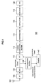
- FIG. 1 is a pattern diagram illustrating a constitution of a receiving apparatus 100 according to one embodiment of the present invention.
- the receiving apparatus 100 is, for example, a receiving apparatus adopting a UWB multi-band OFDM system, and receives a signal transmitted from a transmitting apparatus connected communicably via a wireless communication network.
- the receiving apparatus 100 has an antenna 102, a RF circuit 104, an AD converting section (ADC) 106, an FFT 110, a channel correcting section 112, a deinterleaver 114, a depuncturer 116, a decoder 118, an MAC 120, a synchronizing section 130 and a controller 140.
- ADC AD converting section
- a high-frequency signal received by the antenna 102 is amplified by the RF circuit 104, and is converted into a digital signal by the AD converting section 106.
- the reception signal converted into the digital signal is subject to fast Fourier transformation by the FFT 110 so as to be transmitted to the channel correcting section 112.
- the channel correcting section 112 corrects a channel based on a channel estimating signal (CE) included in the reception signal.
- CE channel estimating signal
- the signal which is corrected by the channel correcting section 112 is sent to the deinterleaver 114.
- the deinterleaver 114 executes a process for returning the interleaved reception signal to an original state.
- the reception signal output from the deinterleaver 114 is sent to the depuncturer 116 so as to be subject to a depuncture process.
- the decoder 118 decodes the signal input from the depuncturer 116.
- the signal decoded by the decoder 118 is input into the MAC 120.
- the synchronizing section 130 acquires synchronism of the signals received by the AD converting sections 66 and 86.
- the controller 140 sends reception timings of the signals synchronized by the synchronizing section 130 to the FFT 110.
- the FFT 110 performs the fast Fourier transformation on the signals based on the reception timings sent from the synchronizing section 130.
- the OFDM system which carries out frequency hopping such as the communication system defined by the IEEE802.15.3 standard, is normally called a multi-band OFDM (MB-OFDM) system.
- MB-OFDM multi-band OFDM
- This system carries out hopping even for transmission of a preamble signal as a frequency acquisition signal, and has various types of hopping patterns and data transmission patterns (Time Frequency Code: hereinafter, TFC).
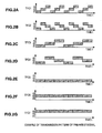
- FIGS. 2A to 2G are pattern diagrams illustrating seven TFCs defined by the IEEE802.15.3 standard. As shown in FIGS. 2A to 2G , seven patterns TFC1 to TFC7 are defined, and a preamble signal as a synchronous signal is transmitted with any one of the seven patterns. Concretely, three frequencies f1, f2 and f3 are prepared as transmission frequencies, and a preamble signal (synchronous signal) of one unit is sent repeatedly 24 times (24 slots) by using any one of three frequencies f1, f2 and f3. FIGS. 2A to 2G show only 12 cycles.
- the frequency is changed into f1, f2 and f3 in this order according to the preamble signal (synchronous signal) of one unit.
- the frequency is changed into f1, f3 and f2 in this order according to the preamble signal of one slot.
- the frequency is changed into f1, f2 and f3 in this order according to the preamble signals of two slots.
- the frequency is changed into f1, f3 and f2 in this order according to the preamble signals of two slots.
- the preamble signals of all the slots are transmitted with the frequency f1.
- the preamble signals of all the slots are transmitted with the frequency f2.
- the preamble signals of all the slots are transmitted with the frequency f3. Not shown here, but signal polarities (+ or -) of the preamble signals are set to predetermined patterns.
- FIG. 3 is a pattern diagram illustrating one example of a data structure of a packet signal received by the receiving apparatus 100.
- the packet signal includes a preamble, a channel estimating signal (CE), a header and a payload.
- the header is classified into a PHY header, a MAC header and a header check sequence (HCE).
- the PHY header includes information such as a payload transmission rate and a payload length.
- the MAC header includes a MAC address showing destination of the packet signal.
- Different preambles are set according to the preamble patterns TFC1 to TFC7 shown in FIGS. 2A to 2G .
- the receiving apparatus 100 acquires synchronism of preamble signals, it can recognize the TFC patterns of the reception signals as the TFC pattern corresponding to the subject apparatus.
- the receiving apparatus 100 when, for example, the setting is such that the receiving apparatus 100 receives the signal of TFC1, it occasionally acquires synchronism due to the reception of the other signals of TFC2 to TFC7.
- the receiving apparatus 100 can determine reception of the other signals of TFCs by means of HCS after the MAC header, but it determines that the reception signal is a signal for the subject apparatus until receiving the HCS of the header. For this reason, although originally the determination can be made that the reception signal is not a signal for the subject apparatus at the time of receiving the preamble, signals from the preamble to the HCS are decoded, and thus an unnecessary process is executed.
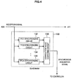
- FIG. 4 is a pattern diagram illustrating in detail a constitution of the synchronizing section 130.
- the synchronizing section 130 has a TFC1 synchronizing circuit 132, a TFC2 synchronizing circuit 134, ..., a TFCm synchronizing circuit 136.
- the synchronizing section 130 has a correlation value comparing circuit 138 which compares correlation values output from the synchronizing circuits 132, 134 and 136.
- the TFC1 synchronizing circuit 132 acquires synchronism at the time of receiving a TFC1 reception signal, and acquires a correlation value of the synchronous signal.
- the TFC2 synchronizing circuit 134 acquires synchronism at the time of receiving a TFC2 reception signal and outputs a correlation value.
- the TFCm synchronizing circuit 136 acquires synchronism at the time of receiving a TFCm reception signal and outputs a correction value.
- FIG. 5 is a pattern diagram illustrating correlation values of the synchronous signals output from the synchronizing circuit 132, 134 and 136 when the receiving apparatus 100 receives a TFC 1 reception signal.
- the synchronizing circuits operate simultaneously at the time of receiving signals. As shown in FIG. 5 , when the receiving apparatus 100 receives a TFC1 reception signal, the TFC1 synchronizing circuit 132 detects a correlation value of a peak value 1. On the other hand, correlation values of synchronous signals detected by the synchronizing circuits 134 and 136 (peak value 2 and peak value m) become smaller than the correlation value detected by the TFC1 synchronizing circuit 132.
- the synchronizing circuits 132, 134 and 136 acquire synchronism when the correlation values exceed a threshold TH. As shown in FIG. 5 , however, when the correlation values output from the synchronizing circuits 132, 134 and 136 exceed the threshold TH, a determination may not be made as to with which TFC pattern the synchronism is acquired.
- the correlation value comparing circuit 138 compares correlation values detected by the synchronizing circuits 132, 134 and 136, and the synchronizing circuit which outputs the largest correlation value is specified. As a result, a determination is made as to which one of TFC1 to TFC7 signals is received.
- the correlation value acquired by the TFC1 synchronizing circuit 132 is larger than the correlation values acquired by the other synchronizing circuits 134 and 136, a determination can be made that the synchronizing circuit with the largest correlation value is the synchronizing circuit 132 corresponding to TFC1. As a result, a determination can be securely made that the reception signal is a TFC1 pattern.
- the reception signal is a TFC pattern for the subject apparatus or a TFC pattern for the other apparatus at the time of receiving payload.
- correlation values not only correlation values at the same time but also correlation values acquired in a predetermined interval B as shown in FIG. 5 are compared.
- the interval B is set according to a preamble signal, a hopping pattern and the like. This is because the timings at which the correlation values are detected differ according to variations of the preamble patterns, the TFC patterns or the hopping patterns.
- a procedure of a process in the receiving apparatus 100 according to the embodiment is described below with reference to FIG. 6 .
- Information about which one of TFC 1 to TFC7 is used by the receiving apparatus 100 is acquired at step S1.
- a user can set in advance TFC which is used by the receiving apparatus 100.
- the signal of the TFCm pattern which is to be used by the receiving apparatus 100 is set in advance.
- Reception is started at a next step S2.
- the reception signal which is digitally converted by the AD converting section 106 is sent to the synchronizing section 130.
- All the synchronizing circuits 132, 134 and 146 are actuated and wait for synchronism at a step S3.
- a next step S4 when the synchronizing circuit 136 corresponding to TFCm used by the receiving apparatus 100 acquires synchronism, namely, the correlation value detected by the synchronizing circuit 136 is larger than the threshold TH, the process goes to a step S5. On the other hand, when it does not acquire synchronism, the process returns to the step S3. Peaks of the correlation values of the synchronizing circuits 132, 134 and 136 are compared within the range of the interval B at the step S5. At a step S6, a determination is made based on the comparison result at step S5. And when the correlation value of the TFCn synchronizing circuit 136 is the maximum, the process goes to a step S7.
- an output from the TFCn synchronizing circuit 136 is output as a final synchronism acquisition signal from the synchronizing section 130 so as to be sent to the controller 140.
- the reception timing due to the synchronism acquisition is sent to the FFT 110, and the reception signal is subject to the fast Fourier Transformation.
- reception of a symbol such as a header after a preamble is ended (RETURN).
- the process in FIG. 6 may be realized by allowing the receiving apparatus 100 as a computer to function according to a program (software) stored in a memory of the receiving apparatus 100, for example.
- the synchronizing circuits 132, 134 and 36 corresponding to a plurality of TFCs are provided, and the correlation values detected by the synchronizing circuits 132, 134 and 136 are compared so that the TFC pattern of the reception signal can be securely recognized. Therefore, the determination can be accurately made based on the TFC pattern whether the reception signal is a signal for the subject apparatus or for another apparatus.
Landscapes
- Engineering & Computer Science (AREA)
- Computer Networks & Wireless Communication (AREA)
- Signal Processing (AREA)
- Synchronisation In Digital Transmission Systems (AREA)
- Mobile Radio Communication Systems (AREA)
Applications Claiming Priority (1)
| Application Number | Priority Date | Filing Date | Title |
|---|---|---|---|
| JP2007305943A JP4577350B2 (ja) | 2007-11-27 | 2007-11-27 | 受信装置、通信システム、受信方法及びプログラム |
Publications (2)
| Publication Number | Publication Date |
|---|---|
| EP2066068A1 true EP2066068A1 (de) | 2009-06-03 |
| EP2066068B1 EP2066068B1 (de) | 2011-09-28 |
Family
ID=40430168
Family Applications (1)
| Application Number | Title | Priority Date | Filing Date |
|---|---|---|---|
| EP20080253509 Not-in-force EP2066068B1 (de) | 2007-11-27 | 2008-10-29 | Empfangsvorrichtung, Kommunikationssystem, Empfangsverfahren und -programm |
Country Status (6)
| Country | Link |
|---|---|
| US (1) | US8259826B2 (de) |
| EP (1) | EP2066068B1 (de) |
| JP (1) | JP4577350B2 (de) |
| KR (1) | KR20090054918A (de) |
| CN (1) | CN101447801B (de) |
| TW (1) | TWI408937B (de) |
Families Citing this family (5)
| Publication number | Priority date | Publication date | Assignee | Title |
|---|---|---|---|---|
| KR101410697B1 (ko) * | 2008-03-20 | 2014-07-02 | 삼성전자주식회사 | 수신기 및 상기 수신기의 동작 제어 방법 |
| US8284873B2 (en) * | 2009-04-07 | 2012-10-09 | Mediatek Inc. | Wireless communication receiver having de-interlever and related signal processing method thereof |
| US9264675B2 (en) * | 2010-04-14 | 2016-02-16 | Hughes Network Systems, Llc | System and method for multi-carrier multiplexing |
| US8831070B2 (en) * | 2010-06-24 | 2014-09-09 | Stichting Imec Nederland | Method and apparatus for start of frame delimiter detection |
| CN115580317B (zh) * | 2022-12-09 | 2023-03-07 | 长沙驰芯半导体科技有限公司 | 一种用于超宽带的同步捕获方法及装置 |
Citations (6)
| Publication number | Priority date | Publication date | Assignee | Title |
|---|---|---|---|---|
| GB2059724A (en) | 1979-09-28 | 1981-04-23 | Racal Datacom Ltd | Data transmission systems |
| EP0358582A2 (de) * | 1988-09-07 | 1990-03-14 | Kokusai Denshin Denwa Co., Ltd | Einzelwortdetektionssystem |
| EP0359582A2 (de) | 1988-09-16 | 1990-03-21 | Ncr International Inc. | Antriebswerk für Geschäftsmaschinentür |
| JP2006197375A (ja) | 2005-01-14 | 2006-07-27 | Sony Corp | 受信方法及び受信機 |
| JP2007019985A (ja) | 2005-07-08 | 2007-01-25 | Mitsubishi Electric Corp | 受信装置 |
| US20070274205A1 (en) * | 2006-05-26 | 2007-11-29 | Texas Instruments Incorporated | Versatile system for interference tolerant packet detection in wireless communication systems |
Family Cites Families (5)
| Publication number | Priority date | Publication date | Assignee | Title |
|---|---|---|---|---|
| JP3630134B2 (ja) * | 2001-11-28 | 2005-03-16 | 日本電気株式会社 | チャネル切替方法及びそれを用いた移動通信端末 |
| US7406070B2 (en) * | 2003-10-09 | 2008-07-29 | Telefonaktiebolaget L M Ericsson (Publ) | Adaptive threshold for HS-SCCH part 1 decoding |
| JP4315886B2 (ja) * | 2004-10-01 | 2009-08-19 | Okiセミコンダクタ株式会社 | スペクトラム拡散信号の同期捕捉方法と回路 |
| TWI288543B (en) * | 2005-07-15 | 2007-10-11 | Faraday Tech Corp | Packet detection system, packet detection device and method for receiving packets |
| TWI292662B (en) * | 2005-07-15 | 2008-01-11 | Faraday Tech Corp | Packet detection device |
-
2007
- 2007-11-27 JP JP2007305943A patent/JP4577350B2/ja not_active Expired - Fee Related
-
2008
- 2008-10-27 TW TW97141230A patent/TWI408937B/zh not_active IP Right Cessation
- 2008-10-29 EP EP20080253509 patent/EP2066068B1/de not_active Not-in-force
- 2008-11-18 US US12/273,229 patent/US8259826B2/en not_active Expired - Fee Related
- 2008-11-25 CN CN2008101791052A patent/CN101447801B/zh not_active Expired - Fee Related
- 2008-11-26 KR KR20080117976A patent/KR20090054918A/ko not_active Abandoned
Patent Citations (6)
| Publication number | Priority date | Publication date | Assignee | Title |
|---|---|---|---|---|
| GB2059724A (en) | 1979-09-28 | 1981-04-23 | Racal Datacom Ltd | Data transmission systems |
| EP0358582A2 (de) * | 1988-09-07 | 1990-03-14 | Kokusai Denshin Denwa Co., Ltd | Einzelwortdetektionssystem |
| EP0359582A2 (de) | 1988-09-16 | 1990-03-21 | Ncr International Inc. | Antriebswerk für Geschäftsmaschinentür |
| JP2006197375A (ja) | 2005-01-14 | 2006-07-27 | Sony Corp | 受信方法及び受信機 |
| JP2007019985A (ja) | 2005-07-08 | 2007-01-25 | Mitsubishi Electric Corp | 受信装置 |
| US20070274205A1 (en) * | 2006-05-26 | 2007-11-29 | Texas Instruments Incorporated | Versatile system for interference tolerant packet detection in wireless communication systems |
Also Published As
| Publication number | Publication date |
|---|---|
| JP2009130814A (ja) | 2009-06-11 |
| TWI408937B (zh) | 2013-09-11 |
| US20090135929A1 (en) | 2009-05-28 |
| JP4577350B2 (ja) | 2010-11-10 |
| HK1130582A1 (en) | 2009-12-31 |
| KR20090054918A (ko) | 2009-06-01 |
| TW200939723A (en) | 2009-09-16 |
| CN101447801A (zh) | 2009-06-03 |
| EP2066068B1 (de) | 2011-09-28 |
| CN101447801B (zh) | 2013-03-06 |
| US8259826B2 (en) | 2012-09-04 |
Similar Documents
| Publication | Publication Date | Title |
|---|---|---|
| JP6073294B2 (ja) | グリーンフィールドプリアンブルを有するショートガードインターバル | |
| US8599824B2 (en) | Method and system for bluetooth conditional synchronization | |
| US7720106B2 (en) | Circuit for synchronizing symbols of OFDM signal | |
| US9124451B2 (en) | Frequency correction circuit, radio receiving apparatus, and frequency correction method | |
| JP2004320739A (ja) | 移動通信端末機のアップリンク/ダウンリンク同期化装置 | |
| US20090016376A1 (en) | Wireless communication apparatus, wireless communication system, wireless communication method and program | |
| US8259826B2 (en) | Receiving apparatus, communication system, receiving method and program | |
| EP2127190A1 (de) | Robuste synchronisation für ein zeitduplexsignal | |
| US6999406B2 (en) | Reception synchronization apparatus and demodulating apparatus using the same | |
| CN113491150A (zh) | 通信设备、其通信方法、信息处理设备、其控制方法及程序 | |
| US10149263B2 (en) | Techniques for transmitting/receiving portions of received signal to identify preamble portion and to determine signal-distorting characteristics | |
| JP4842159B2 (ja) | フレーム同期装置、ofdm送受信装置及びフレーム同期方法 | |
| EP2733901B1 (de) | Kommunikationsverfahren und empfangsvorrichtung | |
| US9083448B2 (en) | Preamble capture and medium access control | |
| KR100808145B1 (ko) | 다중대역 ofdm 초광대역 시스템에서의 시간-주파수코드 검출 장치 및 그 방법 | |
| US8824393B2 (en) | Wireless communication device | |
| WO2007023958A1 (ja) | 無線送信装置及び無線送信方法 | |
| HK1130582B (en) | Receiving apparatus, communication system, receiving method and program | |
| WO2007036847A1 (en) | Fast synchronization for frequency hopping systems | |
| US7580449B2 (en) | DSSS and OFDM two-way waiting reception method and wireless LAN apparatus | |
| JP4332526B2 (ja) | 無線通信受信装置 | |
| KR100887928B1 (ko) | 무선 usb 시스템의 심볼 동기 탐색 방법 | |
| JP2009159168A (ja) | 無線受信機 | |
| JP2005039597A (ja) | タイミング再生回路 | |
| JP2009171152A (ja) | 受信装置、通信システム、受信方法 |
Legal Events
| Date | Code | Title | Description |
|---|---|---|---|
| PUAI | Public reference made under article 153(3) epc to a published international application that has entered the european phase |
Free format text: ORIGINAL CODE: 0009012 |
|
| 17P | Request for examination filed |
Effective date: 20081114 |
|
| AK | Designated contracting states |
Kind code of ref document: A1 Designated state(s): AT BE BG CH CY CZ DE DK EE ES FI FR GB GR HR HU IE IS IT LI LT LU LV MC MT NL NO PL PT RO SE SI SK TR |
|
| AX | Request for extension of the european patent |
Extension state: AL BA MK RS |
|
| 17Q | First examination report despatched |
Effective date: 20090731 |
|
| AKX | Designation fees paid |
Designated state(s): DE FR GB |
|
| GRAP | Despatch of communication of intention to grant a patent |
Free format text: ORIGINAL CODE: EPIDOSNIGR1 |
|
| GRAS | Grant fee paid |
Free format text: ORIGINAL CODE: EPIDOSNIGR3 |
|
| GRAA | (expected) grant |
Free format text: ORIGINAL CODE: 0009210 |
|
| AK | Designated contracting states |
Kind code of ref document: B1 Designated state(s): DE FR GB |
|
| REG | Reference to a national code |
Ref country code: GB Ref legal event code: FG4D |
|
| REG | Reference to a national code |
Ref country code: DE Ref legal event code: R096 Ref document number: 602008010116 Country of ref document: DE Effective date: 20111201 |
|
| PLBE | No opposition filed within time limit |
Free format text: ORIGINAL CODE: 0009261 |
|
| STAA | Information on the status of an ep patent application or granted ep patent |
Free format text: STATUS: NO OPPOSITION FILED WITHIN TIME LIMIT |
|
| 26N | No opposition filed |
Effective date: 20120629 |
|
| REG | Reference to a national code |
Ref country code: DE Ref legal event code: R097 Ref document number: 602008010116 Country of ref document: DE Effective date: 20120629 |
|
| PGFP | Annual fee paid to national office [announced via postgrant information from national office to epo] |
Ref country code: FR Payment date: 20141022 Year of fee payment: 7 Ref country code: GB Payment date: 20141021 Year of fee payment: 7 Ref country code: DE Payment date: 20141022 Year of fee payment: 7 |
|
| REG | Reference to a national code |
Ref country code: DE Ref legal event code: R119 Ref document number: 602008010116 Country of ref document: DE |
|
| GBPC | Gb: european patent ceased through non-payment of renewal fee |
Effective date: 20151029 |
|
| PG25 | Lapsed in a contracting state [announced via postgrant information from national office to epo] |
Ref country code: DE Free format text: LAPSE BECAUSE OF NON-PAYMENT OF DUE FEES Effective date: 20160503 Ref country code: GB Free format text: LAPSE BECAUSE OF NON-PAYMENT OF DUE FEES Effective date: 20151029 |
|
| REG | Reference to a national code |
Ref country code: FR Ref legal event code: ST Effective date: 20160630 |
|
| PG25 | Lapsed in a contracting state [announced via postgrant information from national office to epo] |
Ref country code: FR Free format text: LAPSE BECAUSE OF NON-PAYMENT OF DUE FEES Effective date: 20151102 |