EP2066877B1 - Lift-control device for a poppet valve of an internal-combustion engine or operating machine - Google Patents
Lift-control device for a poppet valve of an internal-combustion engine or operating machine Download PDFInfo
- Publication number
- EP2066877B1 EP2066877B1 EP07789672.8A EP07789672A EP2066877B1 EP 2066877 B1 EP2066877 B1 EP 2066877B1 EP 07789672 A EP07789672 A EP 07789672A EP 2066877 B1 EP2066877 B1 EP 2066877B1
- Authority
- EP
- European Patent Office
- Prior art keywords
- valve
- rocker
- lift
- recess
- pin
- Prior art date
- Legal status (The legal status is an assumption and is not a legal conclusion. Google has not performed a legal analysis and makes no representation as to the accuracy of the status listed.)
- Not-in-force
Links
- 238000002485 combustion reaction Methods 0.000 title claims description 23
- 230000033001 locomotion Effects 0.000 claims description 11
- 230000006835 compression Effects 0.000 claims description 8
- 238000007906 compression Methods 0.000 claims description 8
- 230000009471 action Effects 0.000 claims description 7
- 230000010355 oscillation Effects 0.000 claims description 7
- 238000000034 method Methods 0.000 claims description 6
- 238000006073 displacement reaction Methods 0.000 description 4
- 238000010586 diagram Methods 0.000 description 3
- 230000000903 blocking effect Effects 0.000 description 2
- 230000000694 effects Effects 0.000 description 2
- 239000000446 fuel Substances 0.000 description 2
- 239000007789 gas Substances 0.000 description 2
- 230000002452 interceptive effect Effects 0.000 description 2
- 230000001473 noxious effect Effects 0.000 description 2
- 230000002093 peripheral effect Effects 0.000 description 2
- 230000009467 reduction Effects 0.000 description 2
- 230000003213 activating effect Effects 0.000 description 1
- 230000001276 controlling effect Effects 0.000 description 1
- 230000008878 coupling Effects 0.000 description 1
- 238000010168 coupling process Methods 0.000 description 1
- 238000005859 coupling reaction Methods 0.000 description 1
- 239000012895 dilution Substances 0.000 description 1
- 238000010790 dilution Methods 0.000 description 1
- 238000004880 explosion Methods 0.000 description 1
- 238000005461 lubrication Methods 0.000 description 1
- 230000009347 mechanical transmission Effects 0.000 description 1
- 230000007246 mechanism Effects 0.000 description 1
- 230000001105 regulatory effect Effects 0.000 description 1
- 238000007789 sealing Methods 0.000 description 1
- 239000000243 solution Substances 0.000 description 1
Images


Classifications
-
- F—MECHANICAL ENGINEERING; LIGHTING; HEATING; WEAPONS; BLASTING
- F01—MACHINES OR ENGINES IN GENERAL; ENGINE PLANTS IN GENERAL; STEAM ENGINES
- F01L—CYCLICALLY OPERATING VALVES FOR MACHINES OR ENGINES
- F01L13/00—Modifications of valve-gear to facilitate reversing, braking, starting, changing compression ratio, or other specific operations
- F01L13/0015—Modifications of valve-gear to facilitate reversing, braking, starting, changing compression ratio, or other specific operations for optimising engine performances by modifying valve lift according to various working parameters, e.g. rotational speed, load, torque
-
- F—MECHANICAL ENGINEERING; LIGHTING; HEATING; WEAPONS; BLASTING
- F02—COMBUSTION ENGINES; HOT-GAS OR COMBUSTION-PRODUCT ENGINE PLANTS
- F02D—CONTROLLING COMBUSTION ENGINES
- F02D13/00—Controlling the engine output power by varying inlet or exhaust valve operating characteristics, e.g. timing
- F02D13/02—Controlling the engine output power by varying inlet or exhaust valve operating characteristics, e.g. timing during engine operation
- F02D13/0203—Variable control of intake and exhaust valves
- F02D13/0207—Variable control of intake and exhaust valves changing valve lift or valve lift and timing
- F02D13/0211—Variable control of intake and exhaust valves changing valve lift or valve lift and timing the change of valve timing is caused by the change in valve lift, i.e. both valve lift and timing are functionally related
-
- F—MECHANICAL ENGINEERING; LIGHTING; HEATING; WEAPONS; BLASTING
- F02—COMBUSTION ENGINES; HOT-GAS OR COMBUSTION-PRODUCT ENGINE PLANTS
- F02D—CONTROLLING COMBUSTION ENGINES
- F02D13/00—Controlling the engine output power by varying inlet or exhaust valve operating characteristics, e.g. timing
- F02D13/02—Controlling the engine output power by varying inlet or exhaust valve operating characteristics, e.g. timing during engine operation
- F02D13/0273—Multiple actuations of a valve within an engine cycle
-
- F—MECHANICAL ENGINEERING; LIGHTING; HEATING; WEAPONS; BLASTING
- F01—MACHINES OR ENGINES IN GENERAL; ENGINE PLANTS IN GENERAL; STEAM ENGINES
- F01L—CYCLICALLY OPERATING VALVES FOR MACHINES OR ENGINES
- F01L1/00—Valve-gear or valve arrangements, e.g. lift-valve gear
- F01L1/12—Transmitting gear between valve drive and valve
- F01L1/18—Rocking arms or levers
- F01L2001/186—Split rocking arms, e.g. rocker arms having two articulated parts and means for varying the relative position of these parts or for selectively connecting the parts to move in unison
-
- F—MECHANICAL ENGINEERING; LIGHTING; HEATING; WEAPONS; BLASTING
- F02—COMBUSTION ENGINES; HOT-GAS OR COMBUSTION-PRODUCT ENGINE PLANTS
- F02D—CONTROLLING COMBUSTION ENGINES
- F02D13/00—Controlling the engine output power by varying inlet or exhaust valve operating characteristics, e.g. timing
- F02D13/02—Controlling the engine output power by varying inlet or exhaust valve operating characteristics, e.g. timing during engine operation
- F02D13/04—Controlling the engine output power by varying inlet or exhaust valve operating characteristics, e.g. timing during engine operation using engine as brake
-
- Y—GENERAL TAGGING OF NEW TECHNOLOGICAL DEVELOPMENTS; GENERAL TAGGING OF CROSS-SECTIONAL TECHNOLOGIES SPANNING OVER SEVERAL SECTIONS OF THE IPC; TECHNICAL SUBJECTS COVERED BY FORMER USPC CROSS-REFERENCE ART COLLECTIONS [XRACs] AND DIGESTS
- Y02—TECHNOLOGIES OR APPLICATIONS FOR MITIGATION OR ADAPTATION AGAINST CLIMATE CHANGE
- Y02T—CLIMATE CHANGE MITIGATION TECHNOLOGIES RELATED TO TRANSPORTATION
- Y02T10/00—Road transport of goods or passengers
- Y02T10/10—Internal combustion engine [ICE] based vehicles
- Y02T10/12—Improving ICE efficiencies
Definitions
- the present invention relates to a lift-control device for a poppet valve of an internal-combustion engine or operating machine.
- the invention also relates to a method for control of an internal-combustion engine using the valve-lift control device according to the invention.
- variable-phasing control systems which operate, for example, with valve-control devices (the so-called “tappets") based upon rocker systems.
- the valve-lift timings are regulated by acting in the portion of mechanical transmission of motion between the rocker and the stem of the valve.
- Said systems are, however, far from being versatile, in so far as they are only able to bring forward opening and/or delay closing of the valves themselves.
- US 2005/0000498 describes an apparatus for an internal combustion engine in which a rotatable camshaft has a cam curve designed to interact with a cam follower for operation of an exhaust valve during a first opening and closing phase and also designed to interact with a second cam follower during a second opening and closing phase which is phase - offset with respect to the first opening and closing phase.
- the aim of the present invention is to overcome the limitations of the known art, providing a lift-control device for a poppet valve, particularly but not exclusively an intake valve or an exhaust valve of an internal-combustion engine, that will be able to impose on one and the same valve laws of valve lift even completely different from one another and that, at the same time, will be relatively simple and inexpensive to produce, will be reliable as regards operation, will have small overall dimensions and will be able to work alongside already existing systems for variation of timing of valve opening, for example for bringing forward opening or for delaying closing of the valve, without replacing them and without interfering with their operation.
- a lift-control device for a poppet valve in particular an intake valve or an exhaust valve of an internal-combustion engine, is consequently provided according to what is defined in Claim 1.
- the invention also provides the valve train assembly of Claim 11.
- the invention also provides the method of Claim 12.
- the lift-control device for a poppet valve comprises: first valve-lift means, which define a first valve-lift law and are operatively associated to a rocker that acts on a stem of the valve to move the stem according to the first valve-lift law; second valve-lift means, which define a second valve-lift law and which are also operatively associated to the rocker; and means for selective de-activation of the second valve-lift means.
- the first valve-lift means consist in a profile of a cam or eccentric acting on the rocker in order to cause it to oscillate about a first axis so as to move the valve stem according to the first valve-lift law
- the second valve-lift means consist: in an auxiliary rocker, which co-operates in contact with the first valve-lift means for receiving from said means a motion of oscillation about a second axis parallel to the first; and in a profiled portion of one of the rocker and the auxiliary rocker, having a profile defining the second valve-lift law and co-operating with shoulder means carried by the other of the aforesaid rocker and auxiliary rocker.
- the shoulder means are defined by a slider, which is movable along a pre-set path against the action of elastic means between a first operative position and a second operative position, in particular between a position where it is drawn out from and a position where it is retracted into a seat made in a first end of the auxiliary rocker, it being possible for said shoulder means to be selectively blocked in the first operative position via latch means, which are controlled by hydraulic-actuator means that can be activated selectively.
- the hydraulic-actuator means preferably comprise a source of pressurized oil, a solenoid valve, and a circuit for supply of oil to a piston for actuation of the latch means, which is countered by a return spring, the solenoid valve being designed to connect the circuit for supply of oil to the piston with the source of pressurized oil and with a discharge, selectively.
- the first and second operative positions are located at a pre-set distance along the aforesaid pre-set path, proportional to the extent of a maximum stroke of the valve stem when this is subjected to the second valve-lift law.
- the profiled portion is carried by a prong-shaped end of the rocker that acts on the valve stem and projects in cantilever fashion in the direction of the auxiliary rocker and of the shoulder means, and comprises: a first extent defined by an arc of a circumference having a radius of curvature centred on the aforesaid second axis; and a second extent, which is ramp-shaped and is joined with continuity to the first extent.
- thermodynamic cycle including at least one intake phase, at least one compression phase, and at least one exhaust phase, comprising at least the phase of performing:
- FIG. 1 designated as a whole by 1 is a lift-control device for a poppet valve 2 (only partially illustrated in so far as it is of a well known type), in particular an intake valve or an exhaust valve of an internal-combustion engine 3, known and illustrated schematically only in part for reasons of simplicity.
- a poppet valve 2 only partially illustrated in so far as it is of a well known type
- an intake valve or an exhaust valve of an internal-combustion engine 3 known and illustrated schematically only in part for reasons of simplicity.
- specific reference will be made to the application of the control device 1 to intake and/or exhaust valves 2 of an internal-combustion engine 3, but it is clear that the device 1 that will be described is likewise applicable with equal effectiveness, if need be, to an operating machine, for example, a positive-displacement compressor.
- the control device 1 comprises first valve-lift means 5, which define a first valve-lift law L1 ( Figure 4 ) for the valve 2 and are operatively associated to a rocker 6 that acts on a stem 7 of the valve 2 to move the stem 7 according to the first valve-lift law Ll.
- the valve-lift means 5 will define a known valve-lift law Lib, represented in the right-hand part of the diagram of Figure 4 , which gives on the axis of the abscissa the angle of the output shaft (known and not illustrated) of the engine 3 and on the axis of the ordinate the extent of the vertical displacement of the valve 2 for the different angular positions of the output shaft.
- the corresponding lift means 5 will define a known valve-lift law L1a, represented with a dashed line in the left-hand part of the diagram of Figure 4 .
- the device 1 further comprises second valve-lift means 10, which define a second valve-lift law L2, respectively L2a in the case of an exhaust valve 2 and L2b in the case of an intake valve 2 ( Figure 4 ).
- Said second valve-lift means 10 are also, according to the invention, operatively associated to the rocker 6.
- the device 1 comprises means 12 for selective de-activation of the second valve-lift means 10 so as to be able to position each time the graphs that define the valve-lift laws L2a and L2b in any position along the axis of the abscissa, i.e., for activating/de-activating said second valve-lift means 10 at any angular position of the output shaft of the engine 3.
- the first valve-lift means 5 consist of a peripheral profile of a cam 15 or eccentric, which can rotate about an axis A ( Figure 2 ) and is, in particular, defined by a camshaft 16 connected in a known way to the output shaft of the engine 3, from which it receives the motion of rotation.
- the cam 15 acts on the rocker 6 in a known way, for example by causing its peripheral profile 5 to slide on a roller 18 carried idle in an intermediate position by the rocker 6 so as to cause oscillation of the latter about a first axis B parallel to the axis A.
- the position of the axis B and the shape and dimensions of the rocker 6 are chosen so as to move the valve stem 7 according to the first valve-lift law L1a or Lib (according to whether the valve 2 is an exhaust valve or an intake valve, respectively).
- the second valve-lift means 10 consist of: a coupling in the form of an auxiliary rocker 20, which co-operates in contact with the first valve-lift means 5, i.e., preferably with the profile of the same cam 15, for receiving from said means a motion of oscillation about a second axis C parallel to the axis B; and a profiled portion 21 of one of the rockers 6 and 20, in the case illustrated the rocker 6, having a profile 22 defining the second valve-lift law L2a (or, respectively, L2b) and co-operating with shoulder means 25 carried by the other of the rockers 6 and 20, in the case illustrated the auxillary rocker 20.
- the shoulder means 25 are movable along a pre-set path and against the action of elastic biasing means 26 ( Figure 2 ) between a first operative position and a second operative position and can be selectively blocked in the first operative position (illustrated in Figure 2 ) via latch means 27, better illustrated in Figure 3 .
- the shoulder means 25 consist of a slider 30, possibly terminating with an idle roller 31, slidably carried in cantilever fashion in a rectilinear seat 32 made through a first end 33 of the auxiliary rocker 20 and facing the rocker 6.
- the slider 30 is movable in the seat between a drawn-out position (illustrated in Figure 2 ), in which it is normally held by the elastic means 26 constituted by a helical spring inserted in the seat 20 between an end wall 35 thereof and the slider 30, and a position where it is retracted within the seat 20, in which only the end of the slider 30 provided with the roller 31 comes out therefrom.
- the drawn-out position of the slider 30 corresponds to the aforesaid first operative position of the shoulder means 25, whilst the retracted position of the slider 30 corresponds to the aforesaid second operative position of the shoulder means 25; according to one aspect of the invention, the first and second operative positions are located at a pre-set distance along the aforesaid pre-set path, said pre-set distance being proportional to the extent of a maximum stroke "d" ( Figure 1 ) of the valve stem 7 when this is subjected to the second valve-lift law L2a or L2b ( Figure 4 ).
- the aforesaid pre-set path is defined by the reciprocating rectilinear movement of the slider 30 in the seat 32 between the drawn-out position and the retracted position, and the aforesaid pre-set distance is the stroke of the slider 30.
- Said stroke is defined by end-of-travel means consisting of a pin 38 slidably mounted in a slot 39, which is oriented in a direction parallel to the seat 32.
- the pin 38 is mounted through the end 33 of the auxiliary rocker 20 fixedly to the latter so that it passes transversely through the seat 32, and the slot 39 is made so that it passes transversely through the slider 30 in such a way that said slot 39 defines the aforesaid pre-set path, its length being equal to the aforesaid pre-set distance between the first position and the second position.
- the slot 39 is made through the end 33, and the pin 38 is carried fixedly by the slider 30.
- the latch means 27 are controlled by hydraulic-actuator means 40 ( Figure 1 ) that can be activated selectively, said means comprising a source of pressurized oil constituted by a pump 41 constituting the normal oil pump of the engine 3 for lubrication thereof, which draws the oil from a sump 42 of the engine 3, a circuit 43 for supply of oil to a piston 44 for actuation of the latch means 27, said piston 44 being countered by a return spring 45 ( Figure 3 ), and a solenoid valve 46 designed to connect selectively to the oil-supply circuit 43 with the pump 41 and with a discharge 47 present in the sump 42 constituted by a return circuit for the exhaust oil.
- hydraulic-actuator means 40 Figure 1
- said means comprising a source of pressurized oil constituted by a pump 41 constituting the normal oil pump of the engine 3 for lubrication thereof, which draws the oil from a sump 42 of the engine 3, a circuit 43 for supply of oil to a piston 44 for actuation of the latch means 27, said piston 44 being counter
- the latch means 27 comprise ( Figure 3 ): a first recess 50 made so that it passes transversely through the slider 30, in a direction transverse to the seat 32; a first pin 51, which is slidably housed in the recess 50 and has substantially the same length as the recess 50 itself; and a second recess 52 and a third recess 54, both of which are blind, are made within the end 33 of the auxiliary rocker 20 in a direction transverse to the seat 32, and give out into said seat in a position such that they are aligned with one another and with the recess 50 when the slider is in the drawn-out position.
- auxiliary rocker 20 Moreover provided in the end 33 of the auxiliary rocker 20 is part of the pipe 43 so as to be able to draw in or discharge selectively (by actuation of control means constituted by the solenoid valve 4 6) pressurized oil between an end wall of the recess 52 and the pin-piston 44.
- the rocker 6 that acts on said valve stem is provided with a prong-shaped end 60, which extends in cantilever fashion in the direction of the auxiliary rocker 20 and of the shoulder means 25, which are carried by the end 33 of said auxiliary rocker 20.
- the prong-shaped end 60 is provided, in the direction of the auxiliary rocker 20, with the profiled portion 21, which co-operates in contact, possibly with the interposition of the roller 31, with the shoulder means 25, in the case in point with the end of the slider 30 coming out in cantilever fashion from the seat 32.
- the profiled portion 21 comprises a first extent 61 defined by an arc of a circumference having radius of curvature centred on the axis C of rotation of the rocker 20, and a second ramp-shaped extent 62, joined with continuity to the first extent 61 so as to form the continuous profile 22.
- the auxiliary rocker 20 is constrained in rotation about the axis C via a supporting pin 70 engaging a middle portion of the auxiliary rocker 20, a second end 71 of which, opposite to the end 33, co-operates in contact, possibly with the interposition of a roller 72, with the profile 5 of the cam 15, on the opposite side with respect to the rocker 6.
- the rocker 6 is constrained to rotate about the axis B in its middle portion, via a pin 75.
- the rocker 6 is of the type constrained to oscillate about the axis B in a position corresponding to one end 80 thereof, whilst the cam 15 acts thereon in an intermediate position.
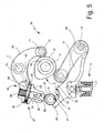
- the device 1b illustrated in Figure 5 is identical to the device 1 of Figures 1 and 2 .
- thermodynamic cycle for example, an Otto cycle or a Diesel cycle
- the rocker 20 co-operates with the rocker 6 through a sort of selectively de-activatable hydraulic tappet, constituted by the shoulder means 25 and by the latch means 27 with their actuation means 40, said tappet being inserted between the rocker 6 and the auxiliary rocker 20, the latter co-operating also with the cam 15 but only for receiving therefrom an oscillating motion, whilst the selectively activatable valve-lift law is established by the profile 22.
- valve-lift law L2b it is possible, for example, to enable part of the burnt gases of the engine 3 to be discharged into the intake manifold of the engine itself, and then be taken in by the engine itself in the subsequent cycle, together with the fresh air and with the fuel. This enables a drastic reduction in noxious emissions, in particular NOx.
- the valvelift law L2a it is, instead, possible to discharge part of the fresh air compressed during the compression phase and before the explosion occurs, thus enabling a considerable increase in the action of engine brake, this being obtained without increasing the consumption of fuel, supply of which may be purposely cut off by a cut-off system governed by the engine electronic control unit that actuates the solenoid valve 46.
- the additional valve-lift law L2a, L2b is obtained only at the moment when the cam 15 will impart an appropriate oscillation on the rocker 20 in phase with the rocker 6 and above all, only when the solenoid valve 46 is actuated so as to govern the latch means 27 and thus block the slider 30 in the drawn-out position. In fact, otherwise, the latch means 27 remain deactivated, and hence the slider 30 remains free to slide within the seat 32.
Landscapes
- Engineering & Computer Science (AREA)
- Mechanical Engineering (AREA)
- General Engineering & Computer Science (AREA)
- Chemical & Material Sciences (AREA)
- Combustion & Propulsion (AREA)
- Valve Device For Special Equipments (AREA)
- Valve-Gear Or Valve Arrangements (AREA)
- Output Control And Ontrol Of Special Type Engine (AREA)
Applications Claiming Priority (2)
| Application Number | Priority Date | Filing Date | Title |
|---|---|---|---|
| IT000563A ITTO20060563A1 (it) | 2006-07-28 | 2006-07-28 | Dispositivo di comando alzata per una valvola a stelo di motore a combustione interna o macchina operatrice |
| PCT/IB2007/002449 WO2008012679A2 (en) | 2006-07-28 | 2007-07-27 | Lift-control device for a poppet valve of an internal-combustion engine or operating machine |
Publications (2)
| Publication Number | Publication Date |
|---|---|
| EP2066877A2 EP2066877A2 (en) | 2009-06-10 |
| EP2066877B1 true EP2066877B1 (en) | 2014-03-05 |
Family
ID=38904677
Family Applications (1)
| Application Number | Title | Priority Date | Filing Date |
|---|---|---|---|
| EP07789672.8A Not-in-force EP2066877B1 (en) | 2006-07-28 | 2007-07-27 | Lift-control device for a poppet valve of an internal-combustion engine or operating machine |
Country Status (4)
| Country | Link |
|---|---|
| US (1) | US8651073B2 (it) |
| EP (1) | EP2066877B1 (it) |
| IT (1) | ITTO20060563A1 (it) |
| WO (1) | WO2008012679A2 (it) |
Families Citing this family (36)
| Publication number | Priority date | Publication date | Assignee | Title |
|---|---|---|---|---|
| US10415439B2 (en) | 2008-07-22 | 2019-09-17 | Eaton Intelligent Power Limited | Development of a switching roller finger follower for cylinder deactivation in internal combustion engines |
| WO2015134466A1 (en) | 2014-03-03 | 2015-09-11 | Eaton Corporation | Valve actuating device and method of making same |
| US9038586B2 (en) | 2010-03-19 | 2015-05-26 | Eaton Corporation | Rocker assembly having improved durability |
| US9938865B2 (en) | 2008-07-22 | 2018-04-10 | Eaton Corporation | Development of a switching roller finger follower for cylinder deactivation in internal combustion engines |
| US8985074B2 (en) | 2010-03-19 | 2015-03-24 | Eaton Corporation | Sensing and control of a variable valve actuation system |
| US20190309663A9 (en) | 2008-07-22 | 2019-10-10 | Eaton Corporation | Development of a switching roller finger follower for cylinder deactivation in internal combustion engines |
| US9267396B2 (en) | 2010-03-19 | 2016-02-23 | Eaton Corporation | Rocker arm assembly and components therefor |
| US9284859B2 (en) | 2010-03-19 | 2016-03-15 | Eaton Corporation | Systems, methods, and devices for valve stem position sensing |
| US9581058B2 (en) | 2010-08-13 | 2017-02-28 | Eaton Corporation | Development of a switching roller finger follower for cylinder deactivation in internal combustion engines |
| US9228454B2 (en) | 2010-03-19 | 2016-01-05 | Eaton Coporation | Systems, methods and devices for rocker arm position sensing |
| US9016252B2 (en) | 2008-07-22 | 2015-04-28 | Eaton Corporation | System to diagnose variable valve actuation malfunctions by monitoring fluid pressure in a hydraulic lash adjuster gallery |
| US9291075B2 (en) | 2008-07-22 | 2016-03-22 | Eaton Corporation | System to diagnose variable valve actuation malfunctions by monitoring fluid pressure in a control gallery |
| US11181013B2 (en) | 2009-07-22 | 2021-11-23 | Eaton Intelligent Power Limited | Cylinder head arrangement for variable valve actuation rocker arm assemblies |
| US10087790B2 (en) | 2009-07-22 | 2018-10-02 | Eaton Corporation | Cylinder head arrangement for variable valve actuation rocker arm assemblies |
| US9194261B2 (en) | 2011-03-18 | 2015-11-24 | Eaton Corporation | Custom VVA rocker arms for left hand and right hand orientations |
| US9885258B2 (en) | 2010-03-19 | 2018-02-06 | Eaton Corporation | Latch interface for a valve actuating device |
| US9874122B2 (en) | 2010-03-19 | 2018-01-23 | Eaton Corporation | Rocker assembly having improved durability |
| US8733732B2 (en) | 2010-05-24 | 2014-05-27 | Eaton Corporation | Pressurized o-ring pole piece seal for a manifold |
| WO2012103401A2 (en) | 2011-01-27 | 2012-08-02 | Scuderi Group, Llc | Lost-motion variable valve actuation system with cam phaser |
| CN103443408A (zh) | 2011-01-27 | 2013-12-11 | 史古德利集团公司 | 具有阀停用的无效运动可变阀致动系统 |
| CN103161543B (zh) * | 2011-12-13 | 2017-09-05 | 常州嵘驰发动机技术有限公司 | 驱动装置、具有该驱动装置的内燃机和使用该内燃机的车辆 |
| US9109468B2 (en) | 2012-01-06 | 2015-08-18 | Scuderi Group, Llc | Lost-motion variable valve actuation system |
| DE102012006342A1 (de) * | 2012-03-28 | 2013-10-02 | Daimler Ag | Verfahren zum Betreiben einer Verbrennungskraftmaschine |
| EP2914820A4 (en) * | 2012-11-05 | 2016-10-05 | Eaton Corp | DEVELOPMENT OF A TOOLED ROLLING TRACK FOR CYLINDER SHUT-OFF IN INTERNAL COMBUSTION ENGINES |
| USD750670S1 (en) | 2013-02-22 | 2016-03-01 | Eaton Corporation | Rocker arm |
| EP2971636A1 (en) | 2013-03-15 | 2016-01-20 | Scuderi Group, Inc. | Split-cycle engines with direct injection |
| AT514535B1 (de) | 2013-06-18 | 2017-05-15 | Avl List Gmbh | Ventilbetätigungseinrichtung |
| KR101534698B1 (ko) * | 2013-09-06 | 2015-07-07 | 현대자동차 주식회사 | 연속 가변 밸브 리프트/타이밍 장치 |
| US10606894B2 (en) | 2017-05-12 | 2020-03-31 | International Business Machines Corporation | Cognitive search query validation |
| AT520278B1 (de) * | 2017-08-01 | 2022-01-15 | Avl List Gmbh | Kopplungsvorrichtung für eine Ventilbetätigungsvorrichtung |
| DE102018207457A1 (de) * | 2018-05-15 | 2019-11-21 | Mahle International Gmbh | Ventiltrieb für eine Brennkraftmaschine |
| WO2020211981A1 (en) * | 2019-04-17 | 2020-10-22 | Eaton Intelligent Power Limited | Rocker arm assembly with lost motion spring capsule |
| WO2021024186A1 (en) * | 2019-08-05 | 2021-02-11 | Jacobs Vehicles Systems, Inc. | Combined positive power and cylinder deactivation operation with secondary valve event |
| AT524194B1 (de) | 2020-08-24 | 2022-12-15 | Avl List Gmbh | Ventilbetätigungsvorrichtung |
| AT524195B1 (de) | 2020-08-24 | 2023-01-15 | Avl List Gmbh | Ventilbetätigungsvorrichtung mit Schaltvorrichtung |
| CN120051627A (zh) * | 2022-10-12 | 2025-05-27 | 康明斯有限公司 | 包括分立空动装置的气门致动系统 |
Family Cites Families (14)
| Publication number | Priority date | Publication date | Assignee | Title |
|---|---|---|---|---|
| EP0336259B1 (en) * | 1988-03-28 | 1994-09-21 | Nissan Motor Co., Ltd. | Operating arrangement for internal combustion engine poppet valves and the like |
| DE68905010T2 (de) * | 1988-08-16 | 1993-09-16 | Nissan Motor | Kipphebelanordnung fuer tellerventile einer brennkraftmaschine. |
| US5048474A (en) * | 1989-02-22 | 1991-09-17 | Nissan Motor Co., Ltd. | Valve train for automotive engine |
| DE4215056A1 (de) * | 1992-05-07 | 1993-11-11 | Audi Ag | Vorrichtung zum desmodromischen Steuern der Gaswechselventile einer Brennkraftmasschine |
| US6053134A (en) * | 1998-08-28 | 2000-04-25 | Linebarger; Terry Glyn | Cam operating system |
| US6487997B2 (en) * | 2001-04-03 | 2002-12-03 | Chris Palumbo | Springless poppet valve system |
| SE521189C2 (sv) | 2002-02-04 | 2003-10-07 | Volvo Lastvagnar Ab | Anordning för att tillföra EGR-gas |
| WO2003087544A2 (en) | 2002-04-08 | 2003-10-23 | Diesel Engine Retarders, Inc. | Compact lost motion system for variable valve actuation |
| US7140333B2 (en) * | 2002-11-12 | 2006-11-28 | Volvo Lastvagnar Ab | Apparatus for an internal combustion engine |
| US6688267B1 (en) * | 2003-03-19 | 2004-02-10 | General Motors Corporation | Engine valve actuator assembly |
| JP4523971B2 (ja) * | 2004-09-09 | 2010-08-11 | ボルボ ラストバグナー アーベー | 内燃機関用装置 |
| US7739989B2 (en) * | 2006-02-08 | 2010-06-22 | Honda Motor Co., Ltd. | Valve-operating mechanism for internal combustion engine |
| US7717075B2 (en) * | 2006-11-14 | 2010-05-18 | Honda Motor Co., Ltd. | Cam mechanism having forced-valve-opening/closing cams and cam-profile setting method |
| US7870842B2 (en) * | 2008-04-07 | 2011-01-18 | Decuir Julian A | Engine with desmodromically actuated rocker |
-
2006
- 2006-07-28 IT IT000563A patent/ITTO20060563A1/it unknown
-
2007
- 2007-07-27 WO PCT/IB2007/002449 patent/WO2008012679A2/en not_active Ceased
- 2007-07-27 US US12/375,355 patent/US8651073B2/en not_active Expired - Fee Related
- 2007-07-27 EP EP07789672.8A patent/EP2066877B1/en not_active Not-in-force
Also Published As
| Publication number | Publication date |
|---|---|
| ITTO20060563A1 (it) | 2008-01-29 |
| US8651073B2 (en) | 2014-02-18 |
| EP2066877A2 (en) | 2009-06-10 |
| WO2008012679A3 (en) | 2008-04-03 |
| WO2008012679A2 (en) | 2008-01-31 |
| US20100095918A1 (en) | 2010-04-22 |
Similar Documents
| Publication | Publication Date | Title |
|---|---|---|
| EP2066877B1 (en) | Lift-control device for a poppet valve of an internal-combustion engine or operating machine | |
| EP3430246B1 (en) | A device for controlling at least one valve in an internal combustion engine | |
| EP2715076B1 (en) | Primary and auxiliary rocker arm assembly for engine valve actuation | |
| US8375904B2 (en) | Early intake valve closing and variable valve timing assembly and method | |
| US7007650B2 (en) | Engine valve actuation system | |
| US20140251266A1 (en) | Auxiliary Valve Motions Employing Disablement of Main Valve Events and/or Coupling of Adjacent Rocker Arms | |
| US6918363B2 (en) | Valve drive apparatus of internal-combustion engine | |
| WO2012048301A4 (en) | Variable compression ratio systems for opposed-piston and other internal combustion engines, and related methods of manufacture and use | |
| JP2004520522A (ja) | ピストン内燃機関用完全可変機械式動弁機構 | |
| CN109715909A (zh) | 具有阀致动装置的内燃机 | |
| EP3051080A1 (en) | Variable valve timing systems for internal combustion engines | |
| JP2003328715A (ja) | エンジンバルブ作動システム | |
| EP4058665B1 (en) | A method for controlling a valve arrangement | |
| JP2016094901A (ja) | 可変動弁装置 | |
| AU2010338453B2 (en) | Mechanical variable valve actuation system for 2-stroke and 4-stroke engine operations | |
| CN114320516A (zh) | 用于选择性停用发动机气门的具有带滚轮锁的摇臂组件的发动机气门系统 | |
| EP3073070A1 (en) | Camshaft based variable valve timing | |
| EP2941548B1 (en) | Valve lifting arrangement and method for operating exhaust valve | |
| JP2007263050A (ja) | 内燃機関 | |
| KR100569377B1 (ko) | 엔진의 연속 가변 밸브 리프트 장치 | |
| KR20080055396A (ko) | 가변 밸브 리프트 장치 | |
| US7047920B2 (en) | Engine valve actuation system and method for controlling white smoke | |
| KR20050120020A (ko) | 자동차용 가변 밸브 리프트 장치 | |
| JP2009281146A (ja) | 内燃機関の動弁装置 | |
| GB2384272A (en) | Valve operating mechanism |
Legal Events
| Date | Code | Title | Description |
|---|---|---|---|
| PUAI | Public reference made under article 153(3) epc to a published international application that has entered the european phase |
Free format text: ORIGINAL CODE: 0009012 |
|
| 17P | Request for examination filed |
Effective date: 20090226 |
|
| AK | Designated contracting states |
Kind code of ref document: A2 Designated state(s): AT BE BG CH CY CZ DE DK EE ES FI FR GB GR HU IE IS IT LI LT LU LV MC MT NL PL PT RO SE SI SK TR |
|
| DAX | Request for extension of the european patent (deleted) | ||
| 17Q | First examination report despatched |
Effective date: 20121102 |
|
| GRAP | Despatch of communication of intention to grant a patent |
Free format text: ORIGINAL CODE: EPIDOSNIGR1 |
|
| INTG | Intention to grant announced |
Effective date: 20131113 |
|
| GRAS | Grant fee paid |
Free format text: ORIGINAL CODE: EPIDOSNIGR3 |
|
| GRAA | (expected) grant |
Free format text: ORIGINAL CODE: 0009210 |
|
| GRAL | Information related to payment of fee for publishing/printing deleted |
Free format text: ORIGINAL CODE: EPIDOSDIGR3 |
|
| GRAS | Grant fee paid |
Free format text: ORIGINAL CODE: EPIDOSNIGR3 |
|
| AK | Designated contracting states |
Kind code of ref document: B1 Designated state(s): AT BE BG CH CY CZ DE DK EE ES FI FR GB GR HU IE IS IT LI LT LU LV MC MT NL PL PT RO SE SI SK TR |
|
| REG | Reference to a national code |
Ref country code: GB Ref legal event code: FG4D |
|
| REG | Reference to a national code |
Ref country code: CH Ref legal event code: EP |
|
| REG | Reference to a national code |
Ref country code: AT Ref legal event code: REF Ref document number: 655040 Country of ref document: AT Kind code of ref document: T Effective date: 20140315 |
|
| REG | Reference to a national code |
Ref country code: IE Ref legal event code: FG4D |
|
| REG | Reference to a national code |
Ref country code: DE Ref legal event code: R096 Ref document number: 602007035393 Country of ref document: DE Effective date: 20140417 |
|
| REG | Reference to a national code |
Ref country code: SE Ref legal event code: TRGR |
|
| REG | Reference to a national code |
Ref country code: AT Ref legal event code: MK05 Ref document number: 655040 Country of ref document: AT Kind code of ref document: T Effective date: 20140305 |
|
| REG | Reference to a national code |
Ref country code: NL Ref legal event code: VDEP Effective date: 20140305 |
|
| PG25 | Lapsed in a contracting state [announced via postgrant information from national office to epo] |
Ref country code: LT Free format text: LAPSE BECAUSE OF FAILURE TO SUBMIT A TRANSLATION OF THE DESCRIPTION OR TO PAY THE FEE WITHIN THE PRESCRIBED TIME-LIMIT Effective date: 20140305 |
|
| REG | Reference to a national code |
Ref country code: LT Ref legal event code: MG4D |
|
| PG25 | Lapsed in a contracting state [announced via postgrant information from national office to epo] |
Ref country code: AT Free format text: LAPSE BECAUSE OF FAILURE TO SUBMIT A TRANSLATION OF THE DESCRIPTION OR TO PAY THE FEE WITHIN THE PRESCRIBED TIME-LIMIT Effective date: 20140305 Ref country code: CY Free format text: LAPSE BECAUSE OF FAILURE TO SUBMIT A TRANSLATION OF THE DESCRIPTION OR TO PAY THE FEE WITHIN THE PRESCRIBED TIME-LIMIT Effective date: 20140305 Ref country code: FI Free format text: LAPSE BECAUSE OF FAILURE TO SUBMIT A TRANSLATION OF THE DESCRIPTION OR TO PAY THE FEE WITHIN THE PRESCRIBED TIME-LIMIT Effective date: 20140305 |
|
| PG25 | Lapsed in a contracting state [announced via postgrant information from national office to epo] |
Ref country code: LV Free format text: LAPSE BECAUSE OF FAILURE TO SUBMIT A TRANSLATION OF THE DESCRIPTION OR TO PAY THE FEE WITHIN THE PRESCRIBED TIME-LIMIT Effective date: 20140305 |
|
| PG25 | Lapsed in a contracting state [announced via postgrant information from national office to epo] |
Ref country code: RO Free format text: LAPSE BECAUSE OF FAILURE TO SUBMIT A TRANSLATION OF THE DESCRIPTION OR TO PAY THE FEE WITHIN THE PRESCRIBED TIME-LIMIT Effective date: 20140305 Ref country code: NL Free format text: LAPSE BECAUSE OF FAILURE TO SUBMIT A TRANSLATION OF THE DESCRIPTION OR TO PAY THE FEE WITHIN THE PRESCRIBED TIME-LIMIT Effective date: 20140305 Ref country code: BE Free format text: LAPSE BECAUSE OF FAILURE TO SUBMIT A TRANSLATION OF THE DESCRIPTION OR TO PAY THE FEE WITHIN THE PRESCRIBED TIME-LIMIT Effective date: 20140305 Ref country code: IS Free format text: LAPSE BECAUSE OF FAILURE TO SUBMIT A TRANSLATION OF THE DESCRIPTION OR TO PAY THE FEE WITHIN THE PRESCRIBED TIME-LIMIT Effective date: 20140705 Ref country code: BG Free format text: LAPSE BECAUSE OF FAILURE TO SUBMIT A TRANSLATION OF THE DESCRIPTION OR TO PAY THE FEE WITHIN THE PRESCRIBED TIME-LIMIT Effective date: 20140605 Ref country code: EE Free format text: LAPSE BECAUSE OF FAILURE TO SUBMIT A TRANSLATION OF THE DESCRIPTION OR TO PAY THE FEE WITHIN THE PRESCRIBED TIME-LIMIT Effective date: 20140305 Ref country code: CZ Free format text: LAPSE BECAUSE OF FAILURE TO SUBMIT A TRANSLATION OF THE DESCRIPTION OR TO PAY THE FEE WITHIN THE PRESCRIBED TIME-LIMIT Effective date: 20140305 |
|
| PG25 | Lapsed in a contracting state [announced via postgrant information from national office to epo] |
Ref country code: SK Free format text: LAPSE BECAUSE OF FAILURE TO SUBMIT A TRANSLATION OF THE DESCRIPTION OR TO PAY THE FEE WITHIN THE PRESCRIBED TIME-LIMIT Effective date: 20140305 Ref country code: PL Free format text: LAPSE BECAUSE OF FAILURE TO SUBMIT A TRANSLATION OF THE DESCRIPTION OR TO PAY THE FEE WITHIN THE PRESCRIBED TIME-LIMIT Effective date: 20140305 Ref country code: ES Free format text: LAPSE BECAUSE OF FAILURE TO SUBMIT A TRANSLATION OF THE DESCRIPTION OR TO PAY THE FEE WITHIN THE PRESCRIBED TIME-LIMIT Effective date: 20140305 |
|
| REG | Reference to a national code |
Ref country code: DE Ref legal event code: R097 Ref document number: 602007035393 Country of ref document: DE |
|
| PG25 | Lapsed in a contracting state [announced via postgrant information from national office to epo] |
Ref country code: PT Free format text: LAPSE BECAUSE OF FAILURE TO SUBMIT A TRANSLATION OF THE DESCRIPTION OR TO PAY THE FEE WITHIN THE PRESCRIBED TIME-LIMIT Effective date: 20140707 |
|
| PLBE | No opposition filed within time limit |
Free format text: ORIGINAL CODE: 0009261 |
|
| STAA | Information on the status of an ep patent application or granted ep patent |
Free format text: STATUS: NO OPPOSITION FILED WITHIN TIME LIMIT |
|
| PG25 | Lapsed in a contracting state [announced via postgrant information from national office to epo] |
Ref country code: DK Free format text: LAPSE BECAUSE OF FAILURE TO SUBMIT A TRANSLATION OF THE DESCRIPTION OR TO PAY THE FEE WITHIN THE PRESCRIBED TIME-LIMIT Effective date: 20140305 |
|
| 26N | No opposition filed |
Effective date: 20141208 |
|
| PG25 | Lapsed in a contracting state [announced via postgrant information from national office to epo] |
Ref country code: LU Free format text: LAPSE BECAUSE OF FAILURE TO SUBMIT A TRANSLATION OF THE DESCRIPTION OR TO PAY THE FEE WITHIN THE PRESCRIBED TIME-LIMIT Effective date: 20140727 |
|
| REG | Reference to a national code |
Ref country code: CH Ref legal event code: PL |
|
| REG | Reference to a national code |
Ref country code: DE Ref legal event code: R097 Ref document number: 602007035393 Country of ref document: DE Effective date: 20141208 |
|
| GBPC | Gb: european patent ceased through non-payment of renewal fee |
Effective date: 20140727 |
|
| REG | Reference to a national code |
Ref country code: IE Ref legal event code: MM4A |
|
| PG25 | Lapsed in a contracting state [announced via postgrant information from national office to epo] |
Ref country code: LI Free format text: LAPSE BECAUSE OF NON-PAYMENT OF DUE FEES Effective date: 20140731 Ref country code: CH Free format text: LAPSE BECAUSE OF NON-PAYMENT OF DUE FEES Effective date: 20140731 |
|
| PG25 | Lapsed in a contracting state [announced via postgrant information from national office to epo] |
Ref country code: SI Free format text: LAPSE BECAUSE OF FAILURE TO SUBMIT A TRANSLATION OF THE DESCRIPTION OR TO PAY THE FEE WITHIN THE PRESCRIBED TIME-LIMIT Effective date: 20140305 Ref country code: GB Free format text: LAPSE BECAUSE OF NON-PAYMENT OF DUE FEES Effective date: 20140727 |
|
| PG25 | Lapsed in a contracting state [announced via postgrant information from national office to epo] |
Ref country code: IE Free format text: LAPSE BECAUSE OF NON-PAYMENT OF DUE FEES Effective date: 20140727 |
|
| PG25 | Lapsed in a contracting state [announced via postgrant information from national office to epo] |
Ref country code: MC Free format text: LAPSE BECAUSE OF FAILURE TO SUBMIT A TRANSLATION OF THE DESCRIPTION OR TO PAY THE FEE WITHIN THE PRESCRIBED TIME-LIMIT Effective date: 20140305 |
|
| REG | Reference to a national code |
Ref country code: FR Ref legal event code: PLFP Year of fee payment: 10 |
|
| PG25 | Lapsed in a contracting state [announced via postgrant information from national office to epo] |
Ref country code: GR Free format text: LAPSE BECAUSE OF FAILURE TO SUBMIT A TRANSLATION OF THE DESCRIPTION OR TO PAY THE FEE WITHIN THE PRESCRIBED TIME-LIMIT Effective date: 20140606 Ref country code: MT Free format text: LAPSE BECAUSE OF FAILURE TO SUBMIT A TRANSLATION OF THE DESCRIPTION OR TO PAY THE FEE WITHIN THE PRESCRIBED TIME-LIMIT Effective date: 20140305 |
|
| PG25 | Lapsed in a contracting state [announced via postgrant information from national office to epo] |
Ref country code: HU Free format text: LAPSE BECAUSE OF FAILURE TO SUBMIT A TRANSLATION OF THE DESCRIPTION OR TO PAY THE FEE WITHIN THE PRESCRIBED TIME-LIMIT; INVALID AB INITIO Effective date: 20070727 Ref country code: TR Free format text: LAPSE BECAUSE OF FAILURE TO SUBMIT A TRANSLATION OF THE DESCRIPTION OR TO PAY THE FEE WITHIN THE PRESCRIBED TIME-LIMIT Effective date: 20140305 |
|
| REG | Reference to a national code |
Ref country code: FR Ref legal event code: PLFP Year of fee payment: 11 |
|
| REG | Reference to a national code |
Ref country code: FR Ref legal event code: PLFP Year of fee payment: 12 |
|
| REG | Reference to a national code |
Ref country code: DE Ref legal event code: R081 Ref document number: 602007035393 Country of ref document: DE Owner name: EATON INTELLIGENT POWER LIMITED, IE Free format text: FORMER OWNER: EATON S.R.L. CON UNICO SOCIO, MILANO, IT |
|
| PGFP | Annual fee paid to national office [announced via postgrant information from national office to epo] |
Ref country code: FR Payment date: 20200623 Year of fee payment: 14 |
|
| PGFP | Annual fee paid to national office [announced via postgrant information from national office to epo] |
Ref country code: SE Payment date: 20200626 Year of fee payment: 14 |
|
| PGFP | Annual fee paid to national office [announced via postgrant information from national office to epo] |
Ref country code: IT Payment date: 20200622 Year of fee payment: 14 |
|
| PGFP | Annual fee paid to national office [announced via postgrant information from national office to epo] |
Ref country code: DE Payment date: 20210622 Year of fee payment: 15 |
|
| PG25 | Lapsed in a contracting state [announced via postgrant information from national office to epo] |
Ref country code: SE Free format text: LAPSE BECAUSE OF NON-PAYMENT OF DUE FEES Effective date: 20210728 Ref country code: FR Free format text: LAPSE BECAUSE OF NON-PAYMENT OF DUE FEES Effective date: 20210731 |
|
| PG25 | Lapsed in a contracting state [announced via postgrant information from national office to epo] |
Ref country code: IT Free format text: LAPSE BECAUSE OF NON-PAYMENT OF DUE FEES Effective date: 20210727 |
|
| REG | Reference to a national code |
Ref country code: DE Ref legal event code: R119 Ref document number: 602007035393 Country of ref document: DE |
|
| PG25 | Lapsed in a contracting state [announced via postgrant information from national office to epo] |
Ref country code: DE Free format text: LAPSE BECAUSE OF NON-PAYMENT OF DUE FEES Effective date: 20230201 |