EP2067194B1 - Zellenmodulkassette und diese enthaltendes mittelgrosses batteriemodul - Google Patents
Zellenmodulkassette und diese enthaltendes mittelgrosses batteriemodul Download PDFInfo
- Publication number
- EP2067194B1 EP2067194B1 EP07808192.4A EP07808192A EP2067194B1 EP 2067194 B1 EP2067194 B1 EP 2067194B1 EP 07808192 A EP07808192 A EP 07808192A EP 2067194 B1 EP2067194 B1 EP 2067194B1
- Authority
- EP
- European Patent Office
- Prior art keywords
- cartridge body
- cartridge
- battery
- coupling
- cell
- Prior art date
- Legal status (The legal status is an assumption and is not a legal conclusion. Google has not performed a legal analysis and makes no representation as to the accuracy of the status listed.)
- Active
Links
Images


Classifications
-
- H—ELECTRICITY
- H01—ELECTRIC ELEMENTS
- H01M—PROCESSES OR MEANS, e.g. BATTERIES, FOR THE DIRECT CONVERSION OF CHEMICAL ENERGY INTO ELECTRICAL ENERGY
- H01M50/00—Constructional details or processes of manufacture of the non-active parts of electrochemical cells other than fuel cells, e.g. hybrid cells
- H01M50/20—Mountings; Secondary casings or frames; Racks, modules or packs; Suspension devices; Shock absorbers; Transport or carrying devices; Holders
- H01M50/202—Casings or frames around the primary casing of a single cell or a single battery
-
- H—ELECTRICITY
- H01—ELECTRIC ELEMENTS
- H01M—PROCESSES OR MEANS, e.g. BATTERIES, FOR THE DIRECT CONVERSION OF CHEMICAL ENERGY INTO ELECTRICAL ENERGY
- H01M50/00—Constructional details or processes of manufacture of the non-active parts of electrochemical cells other than fuel cells, e.g. hybrid cells
- H01M50/20—Mountings; Secondary casings or frames; Racks, modules or packs; Suspension devices; Shock absorbers; Transport or carrying devices; Holders
- H01M50/204—Racks, modules or packs for multiple batteries or multiple cells
- H01M50/207—Racks, modules or packs for multiple batteries or multiple cells characterised by their shape
- H01M50/211—Racks, modules or packs for multiple batteries or multiple cells characterised by their shape adapted for pouch cells
-
- H—ELECTRICITY
- H01—ELECTRIC ELEMENTS
- H01M—PROCESSES OR MEANS, e.g. BATTERIES, FOR THE DIRECT CONVERSION OF CHEMICAL ENERGY INTO ELECTRICAL ENERGY
- H01M50/00—Constructional details or processes of manufacture of the non-active parts of electrochemical cells other than fuel cells, e.g. hybrid cells
- H01M50/50—Current conducting connections for cells or batteries
- H01M50/502—Interconnectors for connecting terminals of adjacent batteries; Interconnectors for connecting cells outside a battery casing
- H01M50/503—Interconnectors for connecting terminals of adjacent batteries; Interconnectors for connecting cells outside a battery casing characterised by the shape of the interconnectors
-
- H—ELECTRICITY
- H01—ELECTRIC ELEMENTS
- H01M—PROCESSES OR MEANS, e.g. BATTERIES, FOR THE DIRECT CONVERSION OF CHEMICAL ENERGY INTO ELECTRICAL ENERGY
- H01M50/00—Constructional details or processes of manufacture of the non-active parts of electrochemical cells other than fuel cells, e.g. hybrid cells
- H01M50/50—Current conducting connections for cells or batteries
- H01M50/502—Interconnectors for connecting terminals of adjacent batteries; Interconnectors for connecting cells outside a battery casing
- H01M50/509—Interconnectors for connecting terminals of adjacent batteries; Interconnectors for connecting cells outside a battery casing characterised by the type of connection, e.g. mixed connections
- H01M50/51—Connection only in series
-
- H—ELECTRICITY
- H01—ELECTRIC ELEMENTS
- H01M—PROCESSES OR MEANS, e.g. BATTERIES, FOR THE DIRECT CONVERSION OF CHEMICAL ENERGY INTO ELECTRICAL ENERGY
- H01M50/00—Constructional details or processes of manufacture of the non-active parts of electrochemical cells other than fuel cells, e.g. hybrid cells
- H01M50/50—Current conducting connections for cells or batteries
- H01M50/502—Interconnectors for connecting terminals of adjacent batteries; Interconnectors for connecting cells outside a battery casing
- H01M50/509—Interconnectors for connecting terminals of adjacent batteries; Interconnectors for connecting cells outside a battery casing characterised by the type of connection, e.g. mixed connections
- H01M50/512—Connection only in parallel
-
- H—ELECTRICITY
- H01—ELECTRIC ELEMENTS
- H01M—PROCESSES OR MEANS, e.g. BATTERIES, FOR THE DIRECT CONVERSION OF CHEMICAL ENERGY INTO ELECTRICAL ENERGY
- H01M50/00—Constructional details or processes of manufacture of the non-active parts of electrochemical cells other than fuel cells, e.g. hybrid cells
- H01M50/50—Current conducting connections for cells or batteries
- H01M50/569—Constructional details of current conducting connections for detecting conditions inside cells or batteries, e.g. details of voltage sensing terminals
-
- H—ELECTRICITY
- H01—ELECTRIC ELEMENTS
- H01M—PROCESSES OR MEANS, e.g. BATTERIES, FOR THE DIRECT CONVERSION OF CHEMICAL ENERGY INTO ELECTRICAL ENERGY
- H01M10/00—Secondary cells; Manufacture thereof
- H01M10/05—Accumulators with non-aqueous electrolyte
- H01M10/052—Li-accumulators
-
- H—ELECTRICITY
- H01—ELECTRIC ELEMENTS
- H01M—PROCESSES OR MEANS, e.g. BATTERIES, FOR THE DIRECT CONVERSION OF CHEMICAL ENERGY INTO ELECTRICAL ENERGY
- H01M10/00—Secondary cells; Manufacture thereof
- H01M10/60—Heating or cooling; Temperature control
- H01M10/61—Types of temperature control
- H01M10/613—Cooling or keeping cold
-
- H—ELECTRICITY
- H01—ELECTRIC ELEMENTS
- H01M—PROCESSES OR MEANS, e.g. BATTERIES, FOR THE DIRECT CONVERSION OF CHEMICAL ENERGY INTO ELECTRICAL ENERGY
- H01M10/00—Secondary cells; Manufacture thereof
- H01M10/60—Heating or cooling; Temperature control
- H01M10/64—Heating or cooling; Temperature control characterised by the shape of the cells
- H01M10/647—Prismatic or flat cells, e.g. pouch cells
-
- H—ELECTRICITY
- H01—ELECTRIC ELEMENTS
- H01M—PROCESSES OR MEANS, e.g. BATTERIES, FOR THE DIRECT CONVERSION OF CHEMICAL ENERGY INTO ELECTRICAL ENERGY
- H01M10/00—Secondary cells; Manufacture thereof
- H01M10/60—Heating or cooling; Temperature control
- H01M10/65—Means for temperature control structurally associated with the cells
- H01M10/655—Solid structures for heat exchange or heat conduction
- H01M10/6554—Rods or plates
- H01M10/6555—Rods or plates arranged between the cells
-
- H—ELECTRICITY
- H01—ELECTRIC ELEMENTS
- H01M—PROCESSES OR MEANS, e.g. BATTERIES, FOR THE DIRECT CONVERSION OF CHEMICAL ENERGY INTO ELECTRICAL ENERGY
- H01M10/00—Secondary cells; Manufacture thereof
- H01M10/60—Heating or cooling; Temperature control
- H01M10/65—Means for temperature control structurally associated with the cells
- H01M10/655—Solid structures for heat exchange or heat conduction
- H01M10/6556—Solid parts with flow channel passages or pipes for heat exchange
- H01M10/6557—Solid parts with flow channel passages or pipes for heat exchange arranged between the cells
-
- H—ELECTRICITY
- H01—ELECTRIC ELEMENTS
- H01M—PROCESSES OR MEANS, e.g. BATTERIES, FOR THE DIRECT CONVERSION OF CHEMICAL ENERGY INTO ELECTRICAL ENERGY
- H01M50/00—Constructional details or processes of manufacture of the non-active parts of electrochemical cells other than fuel cells, e.g. hybrid cells
- H01M50/20—Mountings; Secondary casings or frames; Racks, modules or packs; Suspension devices; Shock absorbers; Transport or carrying devices; Holders
- H01M50/296—Mountings; Secondary casings or frames; Racks, modules or packs; Suspension devices; Shock absorbers; Transport or carrying devices; Holders characterised by terminals of battery packs
-
- Y—GENERAL TAGGING OF NEW TECHNOLOGICAL DEVELOPMENTS; GENERAL TAGGING OF CROSS-SECTIONAL TECHNOLOGIES SPANNING OVER SEVERAL SECTIONS OF THE IPC; TECHNICAL SUBJECTS COVERED BY FORMER USPC CROSS-REFERENCE ART COLLECTIONS [XRACs] AND DIGESTS
- Y02—TECHNOLOGIES OR APPLICATIONS FOR MITIGATION OR ADAPTATION AGAINST CLIMATE CHANGE
- Y02E—REDUCTION OF GREENHOUSE GAS [GHG] EMISSIONS, RELATED TO ENERGY GENERATION, TRANSMISSION OR DISTRIBUTION
- Y02E60/00—Enabling technologies; Technologies with a potential or indirect contribution to GHG emissions mitigation
- Y02E60/10—Energy storage using batteries
Definitions
- the present invention relates to a cell module cartridge used for manufacturing a middle- or large-sized battery module and a middle- or large-sized battery module including the same, and, more particularly, to a cell module cartridge including a cartridge body constructed in a rectangular structure corresponding to a plate-shaped secondary battery cell such that the battery cell is mounted to the cartridge body, the cartridge body being open at the top thereof, and a top cover mounted to the open top of the cartridge body while the battery cell is mounted to the cartridge body, wherein the cartridge body is provided at the bottom thereof with a plurality of through-holes, the cartridge body is provided at one side of the upper and lower ends of each side wall thereof with a coupling protrusion and a coupling groove, and the cartridge body is provided at the front thereof with a coupling part, to which an additional member for mounting an electrode terminal connecting member is coupled in an assembly fashion, such that the electrode terminal connecting member is stably connected to the corresponding electrode terminal of the corresponding battery cell, and a middle- or large-sized battery module including the same.
- a secondary battery which can be charged and discharged, has been widely used as an energy source for wireless mobile devices. Also, the secondary battery has attracted considerable attention as a power source for electric vehicles (EV) and hybrid electric vehicles (HEV), which have been developed to solve problems, such as air pollution, caused by existing gasoline and diesel vehicles using fossil fuel.
- EV electric vehicles
- HEV hybrid electric vehicles
- Small-sized mobile devices use one or several battery cells for each device.
- middle- or large-sized devices such as vehicles, use a middle- or large-sized battery module having a plurality of battery cells electrically connected with each other because high output and large capacity are necessary for the middle- or large-sized devices.
- the size and weight of the battery module is directly related to the receiving space and output of the corresponding middle- or large-sized device. For this reason, manufacturers are trying to manufacture small-sized, light-weight battery modules. Furthermore, devices, which are subject to a large number of external impacts and vibrations, such as electric bicycles and electric vehicles, require stable electrical connection and physical coupling between components constituting the battery module. In addition, a plurality of battery cells are used to accomplish high output and large capacity, and therefore, the safety of the battery module is regarded as important.
- the middle- or large-sized battery module is manufactured with small size and small weight, if possible.
- a prismatic battery or a pouch-shaped battery which can be stacked with high integration and has a small weight to capacity ratio, is usually used as a battery cell of the middle- or large-sized battery module.
- much interest is currently generated in the pouch-shaped battery, including a sheathing member made of an aluminum laminate sheet, because the weight of the pouch-shaped battery is small, and the manufacturing costs of the pouch-shaped battery are low.
- the pouch-shaped battery used as a unit cell of the battery module, has several problems.
- the pouch-shaped battery is constructed in a structure in which the plate-shaped electrode terminals protrude from the upper end of a battery case, with the result that the electrical connection between the electrode terminals necessary for constructing a battery module is difficult.
- the electrical connection between the electrode terminals is accomplished generally by coupling the electrode terminals to each other by welding using wires, plates, or bus bars; however, the coupling between the plate-shaped electrode terminals by welding is not easy.
- the plate-shaped electrode terminals are partially bent, and the metal plates or the bus bars are welded to the bent portions of the plate-shaped electrode terminals, which requires skilled technique and complicates a process for electrically connecting the electrode terminals to each other.
- the coupled region may be separated from each other due to external impact, which causes the defect of the pouch-shaped battery.
- the pouch-shaped battery has a low mechanical strength.
- additional members for maintaining stable coupling and assembly are required when a plurality of batteries are stacked to manufacture a battery module.
- additional mounting members such as cartridges, in each of which one or more unit batteries are mounted, are used when the pouch-shaped batteries are stacked to manufacture the battery module.
- the cartridges are stacked to manufacture the battery module.
- a large number of members are needed generally to accomplish the mechanical coupling and electrical connection between the battery cells or between the unit modules, and a process for assembling the members is very complicated. Furthermore, a space necessary to couple, weld, or solder the members for the mechanical coupling and electrical connection is required, with the result that the total size of the system is increased.
- the output of the device may be unsafe and a short circuit may occur due to the increase of the contact resistance at the electrical connection region of the pouch-shaped battery.
- JP 2005 122927 A is concerned with a battery pack.
- the present invention has been made to solve the above problems, and other technical problems that have yet to be resolved.
- the above and other objects can be accomplished by the provision of a cell module cartridge used for manufacturing a middle- or large-sized battery module as defined in claim 1.
- the cell module cartridge of the present invention can be easily stacked on another cell module, while complementing the low mechanical strength of the battery cells, can easily accomplish the connection between electrode terminals of the battery cells, and can secure appropriate coolant flow channels while the cell module stacked on another cell module.
- the cell module cartridge according to the present invention can be easily assembled and disassembled by virtue of its structural characteristics. Consequently, when the battery cell in the cell module cartridge gets out of order, the battery cell can be easily replaced with a new one. Even when the service life of the battery cell expires, and therefore, the used battery cell is discarded, it is possible to reuse the cell module cartridge. When the battery cell is defective during the manufacture of a battery pack, it is possible to disassemble the cell module cartridge and replace the defective battery cell with a good battery cell, whereby the defect ratio is greatly reduced.
- the mounting insulation member serves to electrically insulate the electrode terminals of the neighboring battery cells from each other.
- the mounting insulation member is made of an electrically insulative material.
- a preferred example of the electrically insulative material may be various plastic resins.
- the material for the mounting insulation member is not particularly restricted so long as the mounting insulation member accomplishes the electric insulation.
- the plate-shaped battery cell is a secondary battery having a small thickness and a relatively large width and length such that, when the plate-shaped battery cell is stacked on another plate-shaped battery cell, the total size of the stacked battery cells is minimized.
- the battery cell is a pouch-shaped battery cell constructed in a structure in which an electrode assembly is mounted in a battery case made of a laminate sheet including a resin layer and a metal layer, and a pair of electrode terminals protrude from one end of the battery case.
- the battery cell may be constructed in a structure in which the electrode assembly is mounted in a pouch-shaped case made of an aluminum laminate sheet.
- the secondary battery constructed in the above-described structure may be referred to as a pouch-shaped battery cell.
- Cathodes, anodes, separators, and an electrolyte, constituting the pouch-shaped battery cell are well known in the art to which the present invention pertains.
- a lithium transition metal oxide such as lithium cobalt oxide, lithium manganese oxide, or lithium nickel oxide, or composite oxide may be used as an active material for the cathodes.
- the through-holes are formed at the cartridge body, as described above, to effectively discharge the heat generated from the battery cell, thereby preventing the overheating of the battery cell.
- the through-holes may be arranged in a predetermined pattern.
- the through-holes may be divided into several through-hole groups, which are spaced a predetermined distance from each other.
- At least one double-sided adhesive tape may be attached to the remaining region of the cartridge body, excluding the region of the cartridge body where the through-hole groups are located, for fixing the battery cell to the cartridge body.
- the double-sided adhesive tape serves to further secure the fixation between the battery cell and the cartridge body by virtue of its double-sided adhesive property. Consequently, when external impacts are applied to the cartridge, the movement of the battery cell in the cartridge is restrained by the double-sided adhesive tape, whereby an internal short circuit of the battery cell is prevented.
- the coupling protrusions and the coupling grooves are formed at opposite side walls of the cartridge such that the stable coupling between the coupling protrusions and the coupling grooves is maintained.
- each cartridge body is provided at the upper end of the rear wall thereof with a coupling concavo-convex part, by which the cartridge body is coupled to another cartridge body, and the cartridge body is provided at the lower end of the rear wall thereof with a coupling groove corresponding to the coupling concavo-convex part, whereby the cartridge bodies are coupled to each other without using additional members.
- the coupling concavo-convex part may be formed at the lower end of the rear wall of each cartridge body, and the coupling groove may be formed at the upper end of the rear wall of each cartridge body.
- a middle- or large-sized battery module is manufactured by a method of stacking a plurality of battery cells with high integration.
- the neighboring battery cells are preferably spaced a predetermined distance from each other so as to effectively remove heat generated during the charge and discharge of the battery cells.
- one or more battery cells, having a low mechanical strength are mounted in a cartridge, and a plurality of cartridges are stacked to construct a battery module. Consequently, it is necessary to form a coolant channel between the stacked cartridges such that heat accumulating between the stacked battery cells is effectively removed.
- the formation of the coolant channel is possible through a structure in which the cartridge body is provided at the upper end of each side wall thereof with at least one protrusion. Consequently, the coolant channel is formed when another cartridge body is stacked on the cartridge body.
- the cartridge bodies are spaced apart a predetermined distance from each other by the protrusions to form the coolant channel, along which a coolant flows.
- a plurality of cartridges are stacked in the height direction.
- the cartridges may be arranged in the lateral direction while being in tight contact with each other.
- the cartridge body may be provided at the front thereof with vertical grooves, into which members ('coupling members') for coupling the cartridge body to another cartridge body in the lateral direction are inserted. Consequently, the coupling members, having a length approximately corresponding to the height of the cartridge body, are coupled to the grooves of the cartridge bodies, which are sequentially stacked, in a sliding fashion, such that the respective cartridge bodies are fixed to each other, to manufacture a middle- or large-sized battery module.
- members 'coupling members'
- the materials for the cartridge body and the top cover are not particularly restricted so long as the cartridge body and the top cover are made of a material exhibiting electrical insulation and having a predetermined mechanical strength.
- the cartridge body and the top cover may be made of metal coated with an insulative material, insulative polymer, or a resin composite thereof, but the material for the cartridge body and the top cover is not limited to the above-specified ones.
- the mounting insulation member is preferably constructed approximately in a hexahedral structure having a size approximately corresponding to the front of the cartridge body, and the mounting insulation member is provided at the top thereof, above the electrode terminal through-holes, with a coupling upper end, which is inserted into the electrode terminal connecting member.
- the mounting insulation member may be coupled to the electrode terminals of the battery cells and the cartridges in various manners.
- the battery cell is mounted on the cartridge body, the electrode terminals of the battery cell are bent downward such that the electrode terminals are brought into tight contact with the coupling part formed at the front end of the cartridge body, and the front end of the cartridge body is inserted into the cartridge coupling groove formed at the rear of the mounting insulation member, whereby the coupling between mounting insulation member and the electrode terminals of the battery cells and the cartridges is accomplished.
- the electrode terminals inserted into the mounting insulation member (the electrode terminals surrounding the front end of the cartridge body) are more securely coupled to the mounting insulation member, when the electrode terminal connecting member is coupled to the mounting insulation member.
- the mounting insulation member is constructed in a structure in which the electrode terminal connecting member for the electrical connection between the battery cells is easily mounted to the mounting insulation member.
- the mounting insulation member may be further provided at the front thereof with a location part, in which the external input and output terminal and the voltage detection terminal of the electrode terminal connecting member are stably located.
- the mounting insulation member may be provided at the location part thereof, in which the external input and output terminal of the electrode terminal connecting member is stably located, with a coupling depression, and the electrode terminals of the battery cell, exposed outward through the electrode terminal through-holes, may be inserted into the rear groove of the bent coupling part of the electrode terminal connecting member.
- a cell module including such a cartridge and such a battery cell.
- the cell module according to the present invention is compact and stable. Furthermore, the cell module can be easily assembled. Consequently, the use and the handling of the cell module is easy.
- at least one double-sided adhesive tape is attached between the cartridge body and the battery cell, as described above, such that the battery cell can be stably fixed in the cartridge when external vibrations and impacts are frequently applied to the cell module.
- a middle- or large-sized battery module constructed in a structure in which a plurality of such cell modules are stacked.
- a plurality of cell modules, as unit bodies, each of which includes a cartridge and a battery cell may be combined to manufacture a middle- or large-sized battery module having high output and large capacity.
- the coupling between the cell modules, as the unit bodies may be accomplished in various different manners.
- the middle- or large-sized battery module is manufactured by mounting a battery cell to a cartridge body, while a top cover, constituting each cell module together with the cartridge body, is separated from the cartridge body, stacking a plurality of such cartridge bodies, coupling the top cover to the uppermost cartridge body, and mechanically coupling electrode terminal connecting members to the front of the cartridge stack.
- the respective battery cells are mounted in cartridges which are open at the tops thereof, not sealed cartridges, the cartridges are stacked, and the open top of the uppermost cartridge is covered by the top cover. Consequently, the number of members used to manufacture the middle- or large-sized battery module is minimized, and therefore, the assembly process is simplified and the manufacturing costs are reduced, whereby it is possible to manufacture a battery module having a more compact structure.
- the electrode terminal connecting members are coupled to the cartridges in a mechanical assembly fashion, without welding or soldering. Consequently, the manufacturing process is easily performed, and the disassembly of the middle- or large-sized battery module is easily performed.
- an elastic single-sided adhesive tape having a predetermined thickness may be attached to the top of each battery cell.
- the adhesive tape fills a space defined between a cartridge and another cartridge stacked on the cartridge, and, at the same time, elastically presses the battery cell such that the battery cell is stably mounted in the corresponding cartridge.
- the single-sided adhesive tape may be an adhesive tape exhibiting elasticity while having a predetermined thickness like a sponge.
- the single-sided adhesive tape may not be attached to the top of the battery cell, but another cartridge body may be brought into direct contact with the top of the battery cell.
- the electrode terminal connecting member includes a coupling part ('bent coupling part') bent to form a groove at the rear of the electrode terminal connecting member such that a plate-shaped electrode terminal of the battery cell ('battery cell electrode terminal') is inserted into the groove, an external input and output terminal protruding toward the front of the electrode terminal connecting member while being bent, and a voltage detection terminal protruding toward the front of the electrode terminal connecting member while being bent.
- a coupling part 'bent coupling part' bent to form a groove at the rear of the electrode terminal connecting member such that a plate-shaped electrode terminal of the battery cell ('battery cell electrode terminal') is inserted into the groove, an external input and output terminal protruding toward the front of the electrode terminal connecting member while being bent, and a voltage detection terminal protruding toward the front of the electrode terminal connecting member while being bent.
- the bent coupling parts and the external input and output terminals of the electrode terminal connecting member are formed in correspondence to the number of battery cells to be electrically connected such that at least two battery cells are electrically connected to each other by the electrode terminal connecting member.
- the shape of the electrode terminal connecting member may be decided depending upon the positions of the battery cells to be electrically connected. For example, when two battery cells are stacked in the height direction, i.e., the battery cells are not arranged at the same height, the bent coupling parts may be formed at different heights.
- the battery module according to the present invention in which the battery cells are sequentially stacked, two bent coupling parts are formed such that the height difference between the bent coupling parts is equivalent to the thickness of the battery cell. Consequently, it is possible to connect the electrode terminals between the battery cells in series and/or parallel with each other in a compact structure, without using additional members.
- the external input and output terminals are provided with coupling holes, through which the connection of external circuits to the external input and output terminals is easily accomplished.
- the external circuits are wires or cables
- the ends of the wires or the cables may be inserted into the corresponding coupling holes, and then a soldering or welding process may be performed.
- bolts may be inserted into the corresponding coupling holes, whereby the mechanical coupling between the ends of the wires or the cables and the external input and output terminals is accomplished.
- the electrode terminal connecting member is not particularly restricted so long as the electrode terminal connecting member is made of a conductive material.
- a nickel plate having a predetermined thickness may be bent in a predetermined shape to manufacture the electrode terminal connecting member.
- a high-output, large-capacity battery module assembly including a plurality of middle- or large-sized battery modules.
- the middle- or large-sized battery modules may be combined in various manners to construct the battery module assembly.
- the battery module assembly is constructed in a structure in which the battery modules are arranged adjacent to each other in the lateral direction, and the battery modules are coupled to each other using coupling members.
- the battery modules may be electrically connected to each other in various structures depending upon a desired capacity and output, and therefore, the battery module assembly is applicable to various devices. Consequently, the middle- or large- sized battery module and the battery module assembly according to the present invention are preferably comprised as a power source for electric vehicles and hybrid electric vehicles, which have a limited installation space and are exposed to frequent vibrations and strong impacts, in consideration of the installation efficiency and the structural stability. More particularly, the battery module assembly according to the present invention is used as a power source for electric vehicles requiring high output and large capacity.
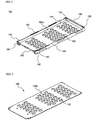
- FIGS. 1 and 2 are perspective views respectively illustrating a cartridge body and a top cover constituting a cell module cartridge according to a preferred embodiment of the present invention
- FIGS. 3 and 4 are typical views illustrating a process for mounting a battery cell to the cell module cartridge of FIG. 1 .
- the cartridge body 100 is constructed in a rectangular structure corresponding to a plate-shaped battery cell 200 (hereinafter, will be shortly referred to as a "battery cell") such that the battery cell 200 is mounted to the cartridge body 100.
- the cartridge body 100 is open at the top thereof.
- the cartridge body 100 is provided at the bottom 110 thereof with a plurality of through-holes 120, arranged in a predetermined pattern, for effectively discharging heat generated from the battery cell 200 and thus preventing the overheating of the battery cell 200.
- the through-holes 120 are divided into several through-hole groups 120a, which are spaced apart from each other by a distance corresponding to each adhesive tape 300, which will be attached to the bottom 110 of the cartridge body 100.
- the top cover 190 is also provided with a plurality of through-holes 120, which are arranged in a predetermined pattern to divide the through-holes 120 into several through-hole groups 120a.
- the cartridge body 100 is provided at one side of the upper end of each side wall 130 thereof with a coupling protrusion 140, by which the cartridge body 100 is another cartridge body (not shown).
- the cartridge body 100 is provided at one side of the lower end of each side wall 130 thereof with a coupling groove 142 corresponding to the coupling protrusion 140.
- the cartridge body 100 is provided at the front 150 thereof with a coupling part 152, to which a mounting insulation member 400 is coupled in an assembly fashion.
- the cartridge body 100 is provided at the upper ends of the opposite side walls 130 thereof with pluralities of protrusions 160, which form a coolant channel when another cartridge body (not shown) is stacked on the cartridge body 100.
- the cartridge bodies are spaced apart a predetermined distance from each other by the protrusions 160 to form the coolant channel, along which a coolant flows.
- the cartridge body 100 is provided at the upper end of a rear wall 170 thereof with a coupling concavo-convex part 180, by which the cartridge body 100 is coupled to another cartridge body.
- the cartridge body 100 is provided at the lower end of the rear wall 170 thereof with a coupling groove 182 corresponding to the coupling concavo-convex part 180.
- the adhesive tapes 300 may be different depending upon whether the adhesive tapes 300 are attached to the top or bottom of the battery cell 200.
- the adhesive tape 300 may be an elastic single-sided adhesive tape having a predetermined thickness and exhibiting an adhesive property only at one side of each adhesive tape 300.
- the adhesive tape 300 may be a double-sided adhesive tape exhibiting an adhesive property at both sides of each adhesive tape 300. The effect resulting from the attachment of the adhesive tapes is the same as in the above description.
- FIG. 5 is a perspective view illustrating a cell module assembled according to a preferred embodiment of the present invention.
- the adhesive tapes 300 are attached to the remaining region of the cartridge body 100, excluding the region of the cartridge body 100 where the through-hole groups 120a are located, and the battery cell 200 is mounted to the cartridge body 100.
- electrode terminals 210 and 220 of the battery cell 200 are bent downward, and are brought into tight contact with the coupling part 152, formed at the front of the cartridge body 100, such that the bent electrode terminals 210 and 220 of the battery cell 200 surround the coupling part 152.
- the mounting insulation member 400 is assembled to the coupling part 152, with which the electrode terminals 210 and 220 of the battery cell 200 are in tight contact.
- an electrode terminal connecting member 410 for electrical connection is coupled to the mounting insulation member 400, the adhesive tapes 300 are attached to the top of the battery cell 200, and the top cover 190 is mounted to the top of the battery cell 200. In this way, the cell module 100a is manufactured.
- the process for manufacturing the cell module may be changed according to circumstances.
- FIGS. 6 to 10 are perspective views illustrating a process for stacking and coupling a plurality of cell module cartridges, one of which is shown in FIGS. 1 to 5 , to manufacture a middle- or large-sized battery module.
- the rear of the second cartridge body 102 is first coupled to the rear of the first cartridge body 101, and then the front of the second cartridge body 102 is rotated downward such that the coupling protrusions 140 can be inserted into the corresponding coupling grooves 142.
- the coupling concavo-convex part 180 is formed at the upper end of the rear wall of the first cartridge body 101, and the coupling groove 182, corresponding to the coupling concavo-convex part 180, are formed at the lower end of the rear wall of the second cartridge body 102. Consequently, when the rear of the second cartridge body 102 is pushed toward the rear of the first cartridge body 101, the coupling concavo-convex part 180 is inserted into the coupling groove 182, whereby the stable coupling between the first cartridge body 101 and the second cartridge body 102 is accomplished.
- the two cartridge bodies 101 and 102 are spaced a predetermined distance from each other by the protrusions 160, formed at the upper ends of the opposite side walls 130 of the first cartridge body 101, to define coolant flow channels 162, 164, and 166, through which heat generated from the battery cell, during the charge and discharge of the battery cell, is effectively cooled.
- the coupling protrusions 140 which are formed at the upper ends of the opposite side walls of the uppermost cartridge body 107, are inserted into coupling grooves 142 formed at the top cover 190, whereby the secure coupling between the uppermost cartridge body 107 and the top cover 190 is accomplished.
- a middle- or large-sized battery module 700 manufactured by the above-described process, is shown in FIG. 8 .
- a plurality of such middle- or large-sized battery modules 700 may be combined to manufacture a large-sized battery module assembly having a desired capacity and output.
- An example of the large-sized battery module assembly is shown in FIGS. 9 and 10 .
- the middle- or large-sized battery module 700 is provided at four corners thereof with grooves 710, into which coupling members 800 and 801 for coupling the middle- or large-sized battery module 700 to another battery middle- or large-sized battery module 701 in the lateral direction are inserted.
- the coupling members 800 and 801 have a length corresponding to the height of the middle- or large-sized battery modules 700 and 701.
- the coupling members 800 and 801 are inserted into the connecting grooves 710, 720, 730, and 740 in a sliding fashion, whereby the battery modules 700 and 701 are coupled to each other, and therefore, a large-sized battery module assembly 900 having a large electric capacity or output as shown in FIG. 10 is manufactured.
- FIGS. 13 to 15 are typical views illustrating various electrode terminal connecting members according to preferred embodiments of the present invention, which are used to manufacture a battery module according to the present invention
- FIG. 16 is a typical view illustrating a mounting insulation member, to which the electrode terminal connecting members are mounted during the construction of the battery module.
- the electrode terminal connecting member 500a shown in FIG. 13 is referred to as an "A-type connecting member”
- the electrode terminal connecting member 500b shown in FIG. 14 is referred to as a "B-type connecting member”
- the electrode terminal connecting member 500c shown in FIG. 15 is referred to as a "C-type connecting member.”
- the electrode terminal connecting member 500a includes a bent coupling part 520a, which is bent to form a groove 540a at the rear of the electrode terminal connecting member 500a such that an electrode terminal (for example, a cathode terminal) of a battery cell (not shown) is inserted into the groove 540a, an external input and output terminal 510a protruding toward the front of the electrode terminal connecting member 500a while being bent, and a voltage detection terminal 530a protruding toward the front of the electrode terminal connecting member 500a while being bent.
- an electrode terminal for example, a cathode terminal
- a battery cell not shown
- the electrode terminal connecting member 500b includes a bent coupling part 520b, which is bent to form a groove 540b at the rear of the electrode terminal connecting member 500b such that an electrode terminal (for example, a cathode terminal) of a battery cell (not shown) is inserted into the groove 540b, an external input and output terminal 510b protruding toward the front of the electrode terminal connecting member 500b while being bent, and a voltage detection terminal 530b protruding toward the front of the electrode terminal connecting member 500b while being bent.
- an electrode terminal for example, a cathode terminal
- a battery cell not shown
- the electrode terminal connecting member 500c includes a bent coupling part 520c, which is bent to form a groove 540c at the rear of the electrode terminal connecting member 500c such that an electrode terminal (for example, a cathode terminal) of a battery cell (not shown) is inserted into the groove 540c, an external input and output terminal 510c protruding toward the front of the electrode terminal connecting member 500c while being bent, and a voltage detection terminal 530c protruding toward the front of the electrode terminal connecting member 500c while being bent.
- an electrode terminal for example, a cathode terminal
- a battery cell not shown
- the external input and output terminal 510a and the voltage detection terminal 330a are bent in parallel to the front of the electrode terminal connecting member 500a.
- the external input and output terminal 510b and the voltage detection terminal 530b are bent in parallel to the front of the electrode terminal connecting member 500b.
- the external input and output terminal 510c and the voltage detection terminal 530c are bent in parallel to the front of the electrode terminal connecting member 500c.
- the bent coupling parts 520a, 520b, and 520c and the external input and output terminals 510a, 510b, and 510c are formed in correspondence to the number of battery cells to be electrically connected.
- the electrode terminal connecting member 500b shown in FIG. 14 includes two bent coupling parts 520b and 521b and two external input and output terminals 510b and 511b, by which electrode terminals of two battery cells are connected in parallel or in series to each other.
- the bent coupling parts 520b and 521b are formed such that the height difference between the bent coupling parts 520b and 521b is equivalent approximately to the thickness of the battery cell.
- the external input and output terminals 510b and 511b are located at opposite ends of the electrode terminal connecting member 500b.
- the voltage detection terminal 530b is located approximately at the middle of the electrode terminal connecting member 500b.
- the external input and output terminals 510a, 510b, and 510c are provided with coupling holes 550a, 550b, and 550c, respectively, through which secure electrical connection using wires is easily accomplished.
- the mounting insulation member 400 is constructed approximately in a rectangular parallelepiped structure. At the rear of the mounting insulation member 400 is formed a cartridge coupling groove 410, in which the front end of a cartridge body (not shown) is inserted. At the front of the mounting insulation member 400 are formed a pair of electrode terminal through-holes 420, through which electrode terminals of a battery cell, introduced through the coupling groove 410, are exposed.
- a coupling upper end 430 which is inserted into the rear groove 540a, 540b, 540c of the bent coupling part 520a, 520b, 520c of the electrode terminal connecting member 500a, 500b, 500c (see FIGS. 13 to 15 ).
- a location part 540 At the front of the mounting insulation member 400 is also formed a location part 540, in which the external input and output terminal 510a, 510b, 510c and the voltage detection terminal 530a, 530b, 530c of the electrode terminal connecting member 500a, 500b, 500c (see FIGS. 13 to 15 ) are stably located. Also, a coupling depression 450 is formed at a position corresponding to the coupling hole 550a, 550b, 550c of the external input and output terminal 510a, 510b, 510c while the electrode terminal connecting member 500a, 500b, 500c is mounted to the mounting insulation member 400.
- FIG. 17 is a typical view illustrating the structure of the middle- or large-sized battery module manufactured in FIG. 8 , which are constructed in a structure in which battery cells are connected in series with each other using the electrode terminal connecting members.
- the middle- or large-sized battery module 700 includes a total of eight battery cells, to each of which a mounting insulation member 400 is coupled while each battery cell is mounted in a cartridge body 100.
- the middle- or large-sized battery module 500 is constructed in a structure in which an A-type connecting member 500a is coupled to a cathode terminal of the battery cell located at the left upper end of the battery module 700, a C-type connecting member 500c is coupled to an anode terminal located at the right lower end of the battery cell of the battery module 700, and B-type connecting members 500b are coupled to the remaining electrode terminals, such that the eight battery cells are connected in series with each other (8S).
- the battery cells constituting the battery module, may be connected in parallel and/or series with each other in various structures in addition to the electrical connection structure shown in FIG. 17 .
- the cell module cartridge according to the present invention restrains the movement of the battery cell, when the battery is dropped or external impacts are applied to the battery, thereby preventing the occurrence of a short circuit in the battery and providing further improved safety of the battery.
- the cell module cartridge according to the present invention accomplishing easy connection between the electrode terminals while complementing the mechanical strength of the pouch-shaped secondary battery, which is a defect of the pouch-shaped secondary battery.
Landscapes
- Chemical & Material Sciences (AREA)
- Chemical Kinetics & Catalysis (AREA)
- Electrochemistry (AREA)
- General Chemical & Material Sciences (AREA)
- Battery Mounting, Suspending (AREA)
- Secondary Cells (AREA)
Claims (18)
- Zellenmodulkassette zur Herstellung eines mittelgroßen oder großen Batteriemoduls, wobei die Zellenmodulkassette beinhaltet:einen Kassettenkörper (100), welcher in einer rechteckigen Struktur gefertigt ist, welche einer plattenförmigen sekundären Batteriezelle (200) ("Batteriezelle") entspricht, sodass die Batteriezelle (200) auf dem Kassettenkörper (100) montiert ist, wobei der Kassettenkörper (100) an der Oberseite davon offen ist, und eine obere Abdeckung (190), welche auf der offenen Oberseite des Kassettenkörpers (100) montiert ist, während die Batteriezelle (200) auf dem Kassettenkörper (100) montiert ist, und wobeider Kassettenkörper (100) an der Unterseite davon mit einer Vielzahl von Durchgangsbohrungen (120) versehen ist, undder Kassettenkörper (100) an einer Seite des oberen Endes jeder Seitenwand davon mit einem Verbindungsvorsprung (140) versehen ist, mittels welchem der Kassettenkörper (100) mit einem anderen Kassettenkörper (100) verbunden ist, während der Kassettenkörper (100) an einer Seite des unteren Endes jeder Seitenwand davon mit einer Verbindungsnut (142) versehen ist, welche dem Verbindungsvorsprung (140) entspricht, dadurch gekennzeichnet, dass:der Kassettenkörper (100) an der Vorderseite davon mit einem Verbindungsteil (152) versehen ist, an welchem ein Montageisolationselement (400), welches ein zusätzliches Element zur Montage eines Elektrodenanschlussverbindungselements ist, in einer Montageart montiert ist, sodass das Elektrodenanschlussverbindungselement (500) ("Element zur elektrischen Verbindung zwischen Elektrodenanschlüssen") stabil mit einem entsprechenden Elektrodenanschluss (210, 220) der entsprechenden Batteriezelle (100) verbunden ist,dadurch, dass das Montageisolationselement (400) an einem hinteren Ende davon mit einer Kassettenverbindungsnut (410) versehen ist, in welche das Verbindungsteil (152) des Kassettenkörpers (100) eingeführt wird, unddadurch, dass das Montageisolationselement (400) an einem vorderen Ende davon mit Elektrodenanschlussdurchgangsbohrungen (420) versehen ist, durch welche Elektrodenanschlüsse (210, 220) der Batteriezelle (100), welche durch die Kassettenverbindungsnut (142) eingebracht wurden, exponiert werden.
- Zellenmodulkassette nach Anspruch 1, wobei die Batteriezelle (100) eine taschenförmige Batteriezelle ist, welche in einer Struktur gefertigt ist, in welcher eine Elektrodenanordnung in einem Batteriegehäuse montiert ist, welches aus einer Schichtfolie einschließlich einer Harzschicht und einer Metallschicht hergestellt ist.
- Zellenmodulkassette nach Anspruch 1, wobei die Durchgangsbohrungen (120) an der Unterseite des Kassettenkörpers (100) in einem vorbestimmten Muster gebildet sind.
- Zellenmodulkassette nach Anspruch 3, wobei die Durchgangsbohrungen (120) in mehrere Gruppen von Durchgangsbohrungen aufgeteilt sind, welche in einer vorbestimmten Entfernung voneinander beabstandet sind.
- Zellenmodulkassette nach Anspruch 1, wobei die Verbindungsvorsprünge (140) und die Verbindungsnuten (142) an gegenüberliegenden Seitenwänden der Kassette gebildet sind.
- Zellenmodulkassette nach Anspruch 1, wobei der Kassettenkörper (100) an dem oberen Ende der Hinterwand davon mit einem konkav-konvexen Verbindungsteil (180) versehen ist, mittels welchem der Kassettenkörper (100) mit einem anderen Kassettenkörper verbunden ist, und der Kassettenkörper (100) an dem unteren Ende der Hinterwand davon mit einer Verbindungsnut (182) versehen ist, welche dem konkav-konvexen Verbindungsteil (180) entspricht.
- Zellenmodulkassette nach Anspruch 1, wobei der Kassettenkörper (100) an dem oberen Ende jeder Seitenwand davon mit zumindest einem Vorsprung (160) versehen ist, welcher einen Kühlmittelkanal bildet, wenn ein weiterer Kassettenkörper auf den Kassettenkörper (100) gestapelt wird.
- Zellenmodulkassette nach Anspruch 1, wobei der Kassettenkörper (100) an der Vorderseite davon mit vertikalen Nuten versehen ist, in welche Elemente ("Verbindungselemente") zum Verbinden des Kassettenkörpers (100) mit einem weiteren Kassettenkörper in der Querrichtung eingeführt werden.
- Zellenmodulkassette nach Anspruch 1, wobei der Kassettenkörper (100) und die obere Abdeckung (190) aus einem isolierenden Material oder einem isolierenden oberflächenbeschichteten Material hergestellt sind.
- Zellenmodulkassette nach Anspruch 1, wobei
das Montageisolationselement (400) annähernd in einer hexaedrischen Struktur mit einer Größe, welche annähernd der Vorderseite des Kassettenkörpers (100) entspricht, gefertigt ist, und
das Montageisolationselement (400) an der Oberseite davon, oberhalb der Elektrodenanschlussdurchgangsbohrungen (420), mit einem oberen Verbindungsende versehen ist, welches in das Elektrodenanschlussverbindungselement (410) eingeführt wird. - Zellenmodul, welches eine Kassette nach Anspruch 1 und eine Batteriezelle beinhaltet.
- Zellenmodul nach Anspruch 11, wobei zumindest ein doppelseitiges Klebeband (300) zwischen dem Kassettenkörper und der Batteriezelle angebracht ist.
- Mittelgroßes oder großes Batteriemodul, welches in einer Struktur gefertigt ist, in welcher eine Vielzahl von Zellenmodulen nach Anspruch 11 gestapelt sind.
- Batteriemodul nach Anspruch 13, wobei das Batteriemodul durch Montieren einer Batteriezelle auf einen Kassettenkörper (100), während eine obere Abdeckung (190), welche jedes Zellenmodul zusammen mit dem Kassettenkörper bildet, von dem Kassettenkörper (100) getrennt wird, Stapeln einer Vielzahl von solchen Kassettenkörpern, Verbinden der oberen Abdeckung (190) mit dem obersten Kassettenkörper, und mechanisches Verbinden der Elektrodenanschlussverbindungselemente mit der Vorderseite des Kassettenstapels hergestellt wird.
- Batteriemodul nach Anspruch 14, wobei ein elastisches einseitiges Klebeband (300) mit einer vorbestimmten Dicke an der Oberseite jeder Batteriezelle, welche die gestapelten Kassettenkörper bilden, angebracht wird.
- Batteriemodul nach Anspruch 14, wobei jedes Elektrodenanschlussverbindungselement (500a) beinhaltet
ein Verbindungsteil (520a) ("gebogener Verbindungsteil"), welcher gebogen ist, um eine Nut an der Rückseite des Elektrodenanschlussverbindungselements (500a) zu bilden, sodass ein Elektrodenanschluss von jeder Batteriezelle in die Nut eingeführt wird,
einen externen Eingangs- und Ausgangsanschluss (510a), welcher, während er gebogen wird, in Richtung der Vorderseite des Elektrodenanschlussverbindungselements (500a) vorsteht, und
einen Spannungserkennungsanschluss (530a), welcher, während er gebogen wird, in Richtung der Vorderseite des Elektrodenanschlussverbindungselements (500a) vorsteht. - Batteriemodulanordnung mit hoher Ausgangsleistung und großer Kapazität, welche eine Vielzahl von Batteriemodulen nach Anspruch 14 beinhaltet, wobei die Batteriemodulanordnung in einer Struktur gefertigt ist, in welcher die Batteriemodule in der Querrichtung zueinander benachbart angeordnet sind, und die Batteriemodule unter Verwendung von Verbindungselementen miteinander verbunden sind.
- Batteriemodulanordnung nach Anspruch 17, wobei die Batteriemodulanordnung als eine Lade- und Entladestromquelle für elektrische Fahrzeuge oder elektrische Hybridfahrzeuge ausgeführt ist.
Applications Claiming Priority (3)
| Application Number | Priority Date | Filing Date | Title |
|---|---|---|---|
| KR1020060092600A KR100921346B1 (ko) | 2006-09-25 | 2006-09-25 | 중대형 전지모듈 및 전지모듈 어셈블리 |
| KR1020060102640A KR100894407B1 (ko) | 2006-10-23 | 2006-10-23 | 셀 모듈 카트리지 및 이를 포함하고 있는 셀 모듈 |
| PCT/KR2007/004400 WO2008038914A1 (en) | 2006-09-25 | 2007-09-12 | Cell-module cartridge and mid-large battery module including the same |
Publications (4)
| Publication Number | Publication Date |
|---|---|
| EP2067194A1 EP2067194A1 (de) | 2009-06-10 |
| EP2067194A4 EP2067194A4 (de) | 2015-12-02 |
| EP2067194B1 true EP2067194B1 (de) | 2018-05-30 |
| EP2067194B8 EP2067194B8 (de) | 2018-07-18 |
Family
ID=39230318
Family Applications (1)
| Application Number | Title | Priority Date | Filing Date |
|---|---|---|---|
| EP07808192.4A Active EP2067194B8 (de) | 2006-09-25 | 2007-09-12 | Zellenmodulkassette und diese enthaltendes mittelgrosses batteriemodul |
Country Status (4)
| Country | Link |
|---|---|
| US (1) | US7858229B2 (de) |
| EP (1) | EP2067194B8 (de) |
| JP (1) | JP5259602B2 (de) |
| WO (1) | WO2008038914A1 (de) |
Families Citing this family (59)
| Publication number | Priority date | Publication date | Assignee | Title |
|---|---|---|---|---|
| US10014508B2 (en) | 2006-11-27 | 2018-07-03 | Lg Chem, Ltd. | Battery module assembly |
| KR100920207B1 (ko) | 2006-11-27 | 2009-10-06 | 주식회사 엘지화학 | 전지모듈 어셈블리 제조용 전원 스위칭 모듈 |
| US8202645B2 (en) * | 2008-10-06 | 2012-06-19 | Lg Chem, Ltd. | Battery cell assembly and method for assembling the battery cell assembly |
| DE102009018787A1 (de) * | 2009-04-24 | 2010-10-28 | Akasol Engineering Gmbh | Batteriemodul |
| JP5393365B2 (ja) * | 2009-09-11 | 2014-01-22 | 日産自動車株式会社 | 電池モジュール |
| DE102009052508A1 (de) * | 2009-11-11 | 2011-05-12 | Carl Freudenberg Kg | Mechanisch flexibles und poröses Ausgleichselement zur Temperierung elektrochemischer Zellen |
| WO2011065674A2 (ko) * | 2009-11-27 | 2011-06-03 | (주)브이이엔에스 | 전지 카트리지 |
| KR101271567B1 (ko) * | 2010-08-16 | 2013-06-11 | 주식회사 엘지화학 | 고정부재가 플레이트들의 관통구에 삽입되어 있는 구조의 전지모듈 및 이를 포함하는 전지팩 |
| KR101403930B1 (ko) | 2010-08-16 | 2014-07-01 | 주식회사 엘지화학 | 콤팩트한 구조의 전지팩 |
| KR101243908B1 (ko) * | 2010-10-12 | 2013-03-14 | 삼성에스디아이 주식회사 | 단위 전지 및 전지 모듈 |
| WO2012070782A2 (ko) * | 2010-11-22 | 2012-05-31 | 주식회사 엘지화학 | 콤팩트한 구조의 전지팩 |
| JP2012212608A (ja) * | 2011-03-31 | 2012-11-01 | Nec Energy Devices Ltd | 電池パック |
| JP5831924B2 (ja) * | 2011-03-31 | 2015-12-09 | Necエナジーデバイス株式会社 | 電池パック |
| WO2012131798A1 (ja) * | 2011-03-31 | 2012-10-04 | Necエナジーデバイス株式会社 | 電池パックおよび電動自転車 |
| US9356278B2 (en) | 2011-03-31 | 2016-05-31 | Nec Energy Devices, Ltd. | Battery pack |
| KR101252950B1 (ko) | 2011-04-21 | 2013-04-15 | 로베르트 보쉬 게엠베하 | 엔드 플레이트의 체결 구조가 개선된 배터리 모듈 |
| KR101355961B1 (ko) * | 2011-04-25 | 2014-02-03 | 주식회사 엘지화학 | 배터리팩 수납장치 및 이를 이용한 전력 저장용 배터리팩의 냉각 장치 |
| KR101255542B1 (ko) * | 2011-05-12 | 2013-04-16 | 삼성에스디아이 주식회사 | 전지 팩 |
| KR101282519B1 (ko) | 2011-08-02 | 2013-07-04 | 로베르트 보쉬 게엠베하 | 배터리 모듈 |
| KR101288121B1 (ko) * | 2011-08-24 | 2013-07-19 | 삼성에스디아이 주식회사 | 이차전지 및 이차전지 모듈 |
| US9450219B2 (en) | 2011-09-15 | 2016-09-20 | Samsung Sdi Co., Ltd. | Battery module |
| KR101883915B1 (ko) * | 2011-09-30 | 2018-08-02 | 삼성에스디아이 주식회사 | 지지부재를 포함하는 배터리 모듈 |
| KR101480385B1 (ko) | 2011-12-14 | 2015-01-09 | 주식회사 엘지화학 | 버스 바 어셈블리가 전면에 장착된 전지모듈 어셈블리 및 이를 포함하는 중대형 전지팩 |
| KR101501431B1 (ko) * | 2012-07-23 | 2015-03-12 | 주식회사 엘지화학 | 파우치형 전지셀이 내장되어 있는 각형화된 전지셀 |
| CN102903865A (zh) * | 2012-11-06 | 2013-01-30 | 无锡东港电池配件有限公司 | 一种电池钢壳结构 |
| US9525195B2 (en) * | 2013-07-30 | 2016-12-20 | Johnson Controls Technology Corporation | Remanufacturing methods for battery module |
| KR101709562B1 (ko) * | 2013-07-31 | 2017-03-08 | 주식회사 엘지화학 | 전지모듈 어셈블리 |
| KR101692790B1 (ko) * | 2013-07-31 | 2017-01-04 | 주식회사 엘지화학 | 냉매 유로를 포함하는 전지모듈 어셈블리 |
| EP3018733B1 (de) | 2013-08-23 | 2017-06-14 | LG Chem, Ltd. | Stapelbares batteriemodul mit leicht veränderbarer verbindungsstruktur |
| JP6233076B2 (ja) * | 2014-02-06 | 2017-11-22 | 株式会社豊田自動織機 | 電池モジュール |
| KR101773105B1 (ko) * | 2014-07-31 | 2017-08-30 | 주식회사 엘지화학 | 배터리 모듈 |
| EP3166176B1 (de) * | 2014-10-29 | 2018-12-26 | LG Chem, Ltd. | Batterie-pack-einheit |
| KR101787638B1 (ko) | 2014-11-05 | 2017-10-19 | 주식회사 엘지화학 | 이중 측벽 구조를 가지는 카트리지 프레임 및 이를 포함하는 배터리 모듈 |
| US9620764B2 (en) | 2015-01-05 | 2017-04-11 | Johnson Controls Technology Company | Battery module cooling fins and footings system and method |
| WO2016157263A1 (ja) * | 2015-03-31 | 2016-10-06 | 三洋電機株式会社 | 電源装置及びこれを備える車両 |
| KR101881196B1 (ko) | 2015-06-16 | 2018-07-23 | 주식회사 엘지화학 | 전지 팩 |
| KR101953362B1 (ko) * | 2015-09-02 | 2019-05-22 | 주식회사 엘지화학 | 개선된 체결구조를 갖는 배터리 모듈 |
| KR102024326B1 (ko) * | 2015-10-14 | 2019-09-23 | 주식회사 엘지화학 | 배터리 모듈 및 이를 포함하는 배터리 팩 |
| WO2017104877A1 (ko) * | 2015-12-18 | 2017-06-22 | 주식회사 엘지화학 | 배터리 모듈 |
| US10632857B2 (en) | 2016-08-17 | 2020-04-28 | Shape Corp. | Battery support and protection structure for a vehicle |
| CN110383526A (zh) | 2017-01-04 | 2019-10-25 | 形状集团 | 节点模块化的车辆电池托盘结构 |
| KR102097087B1 (ko) | 2017-04-07 | 2020-04-03 | 주식회사 엘지화학 | 배터리 모듈 및 이를 포함하는 배터리 팩 및 자동차 |
| US10483510B2 (en) | 2017-05-16 | 2019-11-19 | Shape Corp. | Polarized battery tray for a vehicle |
| US10886513B2 (en) | 2017-05-16 | 2021-01-05 | Shape Corp. | Vehicle battery tray having tub-based integration |
| WO2018213383A1 (en) | 2017-05-16 | 2018-11-22 | Shape Corp. | Vehicle battery tray with integrated battery retention and support features |
| US12347879B2 (en) | 2017-09-13 | 2025-07-01 | Shape Corp. | Vehicle battery tray with tubular peripheral wall |
| CN111108015A (zh) | 2017-09-13 | 2020-05-05 | 形状集团 | 具有管状外围壁的车辆电池托盘 |
| WO2019071013A1 (en) | 2017-10-04 | 2019-04-11 | Shape Corp. | BATTERY SUPPORT BOTTOM ASSEMBLY FOR ELECTRIC VEHICLES |
| KR102059614B1 (ko) * | 2017-11-14 | 2019-12-26 | 주식회사 엘지화학 | 고정부를 포함하는 배터리 팩 |
| US10766437B2 (en) * | 2017-12-14 | 2020-09-08 | Volkswagen Ag | Electric vehicle safety system and methods |
| EP3759761B1 (de) | 2018-03-01 | 2026-04-08 | Shape Corp. | In fahrzeugbatteriefach integriertes kühlsystem |
| US11688910B2 (en) | 2018-03-15 | 2023-06-27 | Shape Corp. | Vehicle battery tray having tub-based component |
| KR102523702B1 (ko) | 2018-07-03 | 2023-04-19 | 주식회사 엘지에너지솔루션 | 배터리 모듈 |
| JP6706294B2 (ja) * | 2018-08-31 | 2020-06-03 | 本田技研工業株式会社 | バッテリパックの冷却構造 |
| JP6683779B2 (ja) | 2018-08-31 | 2020-04-22 | 本田技研工業株式会社 | バッテリパックの冷却構造 |
| CN110429223B (zh) * | 2019-09-05 | 2024-11-08 | 珠海格力电器股份有限公司 | 电芯固定结构、电池模块、电池模组 |
| CN210576107U (zh) * | 2019-09-20 | 2020-05-19 | 宁德时代新能源科技股份有限公司 | 电池模组、电池包以及车辆 |
| US12597656B2 (en) * | 2021-02-24 | 2026-04-07 | Ocella, Inc. | Assemblies and methods thereof for attaching energy storage devices to devices in need thereof |
| KR102870579B1 (ko) * | 2021-10-26 | 2025-10-15 | 주식회사 엘지에너지솔루션 | 배터리 팩 |
Family Cites Families (20)
| Publication number | Priority date | Publication date | Assignee | Title |
|---|---|---|---|---|
| JP3627480B2 (ja) * | 1997-11-28 | 2005-03-09 | 松下電器産業株式会社 | 集合電池 |
| US6319631B1 (en) * | 1999-09-08 | 2001-11-20 | Motorola, Inc. | Contact system for interconnection of substrate and battery cell |
| JP4642179B2 (ja) * | 1999-10-08 | 2011-03-02 | パナソニック株式会社 | 集合型二次電池 |
| KR100362277B1 (ko) | 2000-04-10 | 2002-11-23 | 삼성에스디아이 주식회사 | 보호 케이스를 가지는 이차 전지 |
| JP4196521B2 (ja) * | 2000-05-19 | 2008-12-17 | 新神戸電機株式会社 | 電気自動車用バッテリ構造及び電池モジュール |
| JP4214450B2 (ja) * | 2002-06-03 | 2009-01-28 | 日本電気株式会社 | モジュール |
| JP3644444B2 (ja) * | 2002-07-23 | 2005-04-27 | 日産自動車株式会社 | モジュール電池 |
| JP2005116407A (ja) * | 2003-10-09 | 2005-04-28 | Tdk Corp | 電池パック |
| TWI246213B (en) | 2003-10-14 | 2005-12-21 | Lg Chemical Ltd | Cartridge-type lithium ion polymer battery pack |
| JP4706170B2 (ja) * | 2003-10-14 | 2011-06-22 | 株式会社Gsユアサ | 組電池 |
| KR100556101B1 (ko) * | 2003-12-16 | 2006-03-03 | 주식회사 엘지화학 | 이차전지 모듈 |
| JP4400234B2 (ja) * | 2004-02-03 | 2010-01-20 | 新神戸電機株式会社 | 組電池 |
| CN1922745B (zh) * | 2004-02-18 | 2010-12-01 | 株式会社Lg化学 | 含有保护电路板的整体帽盖组件以及包括该帽盖组件的二次电池 |
| JP4617098B2 (ja) * | 2004-04-12 | 2011-01-19 | 内山工業株式会社 | バッテリーセル用ケース |
| KR100891080B1 (ko) | 2004-12-02 | 2009-03-30 | 주식회사 엘지화학 | 전지 팩 제조용 전지 연결부재 |
| KR100850849B1 (ko) | 2004-12-09 | 2008-08-06 | 주식회사 엘지화학 | 열 제어를 위한 전지 케이스 및 그를 이용한 전지팩 구조 |
| KR100876458B1 (ko) | 2004-12-24 | 2008-12-29 | 주식회사 엘지화학 | 신규한 구조의 전지 카트리지와 그것을 포함하고 있는개방형 전지 모듈 |
| KR100880389B1 (ko) * | 2004-12-24 | 2009-01-23 | 주식회사 엘지화학 | 이차전지 모듈의 제조방법 |
| KR100905391B1 (ko) * | 2004-12-24 | 2009-06-30 | 주식회사 엘지화학 | 이차전지 모듈의 단자 연결부재 |
| KR100891079B1 (ko) * | 2005-02-07 | 2009-03-30 | 주식회사 엘지화학 | 전지 모듈용 전지 카트리지 연결 시스템 |
-
2007
- 2007-09-12 EP EP07808192.4A patent/EP2067194B8/de active Active
- 2007-09-12 US US12/442,614 patent/US7858229B2/en active Active
- 2007-09-12 JP JP2009530251A patent/JP5259602B2/ja active Active
- 2007-09-12 WO PCT/KR2007/004400 patent/WO2008038914A1/en not_active Ceased
Non-Patent Citations (1)
| Title |
|---|
| None * |
Also Published As
| Publication number | Publication date |
|---|---|
| US20100136420A1 (en) | 2010-06-03 |
| EP2067194A1 (de) | 2009-06-10 |
| JP5259602B2 (ja) | 2013-08-07 |
| EP2067194B8 (de) | 2018-07-18 |
| EP2067194A4 (de) | 2015-12-02 |
| JP2010504622A (ja) | 2010-02-12 |
| WO2008038914A1 (en) | 2008-04-03 |
| US7858229B2 (en) | 2010-12-28 |
Similar Documents
| Publication | Publication Date | Title |
|---|---|---|
| EP2067194B1 (de) | Zellenmodulkassette und diese enthaltendes mittelgrosses batteriemodul | |
| US7976978B2 (en) | Member of connecting electrode in battery module | |
| EP1812982B1 (de) | Sekundärbatteriepack mit anordnung zu alternativer ausrichtung | |
| EP1994581B1 (de) | Mittel- oder sehr grosses batteriemodul | |
| EP2535962B1 (de) | Batteriemodul mit verstärkter schweissungszuverlässigkeit sowie mittleres oder grosses batteriepaket damit | |
| US7892669B2 (en) | Middle or large-sized battery module | |
| EP2025019B1 (de) | Mittel- oder sehr grosses batteriemodul | |
| KR100921346B1 (ko) | 중대형 전지모듈 및 전지모듈 어셈블리 | |
| EP2064761B1 (de) | Batteriemodul und mittelgrosses oder grosses batteriepack damit | |
| EP1992026B1 (de) | Batteriemodul | |
| EP2853436B1 (de) | Batteriemodul mit indirekter luftkühlungsstruktur | |
| EP2765632A1 (de) | Batteriemodulbaugruppe mit verbesserter zuverlässigkeit sowie mittelgrosses und grosses batteriepack damit | |
| WO2009061088A1 (en) | Battery cell having improved thermal stability and middle or large-sized battery module employed with the same | |
| KR20080074239A (ko) | 수명 특성과 안전성이 우수한 고용량 전지셀 |
Legal Events
| Date | Code | Title | Description |
|---|---|---|---|
| PUAI | Public reference made under article 153(3) epc to a published international application that has entered the european phase |
Free format text: ORIGINAL CODE: 0009012 |
|
| 17P | Request for examination filed |
Effective date: 20090323 |
|
| AK | Designated contracting states |
Kind code of ref document: A1 Designated state(s): AT BE BG CH CY CZ DE DK EE ES FI FR GB GR HU IE IS IT LI LT LU LV MC MT NL PL PT RO SE SI SK TR |
|
| AX | Request for extension of the european patent |
Extension state: AL BA HR MK RS |
|
| DAX | Request for extension of the european patent (deleted) | ||
| RBV | Designated contracting states (corrected) |
Designated state(s): DE FR GB IT |
|
| RA4 | Supplementary search report drawn up and despatched (corrected) |
Effective date: 20151102 |
|
| RIC1 | Information provided on ipc code assigned before grant |
Ipc: H01M 2/22 20060101AFI20151027BHEP |
|
| GRAP | Despatch of communication of intention to grant a patent |
Free format text: ORIGINAL CODE: EPIDOSNIGR1 |
|
| INTG | Intention to grant announced |
Effective date: 20180214 |
|
| GRAS | Grant fee paid |
Free format text: ORIGINAL CODE: EPIDOSNIGR3 |
|
| GRAA | (expected) grant |
Free format text: ORIGINAL CODE: 0009210 |
|
| AK | Designated contracting states |
Kind code of ref document: B1 Designated state(s): DE FR GB IT |
|
| GRAT | Correction requested after decision to grant or after decision to maintain patent in amended form |
Free format text: ORIGINAL CODE: EPIDOSNCDEC |
|
| REG | Reference to a national code |
Ref country code: GB Ref legal event code: FG4D |
|
| REG | Reference to a national code |
Ref country code: DE Ref legal event code: R096 Ref document number: 602007054992 Country of ref document: DE |
|
| RAP2 | Party data changed (patent owner data changed or rights of a patent transferred) |
Owner name: LG CHEM, LTD. |
|
| REG | Reference to a national code |
Ref country code: DE Ref legal event code: R082 Ref document number: 602007054992 Country of ref document: DE Representative=s name: HOFFMANN - EITLE PATENT- UND RECHTSANWAELTE PA, DE |
|
| REG | Reference to a national code |
Ref country code: FR Ref legal event code: PLFP Year of fee payment: 12 |
|
| RAP2 | Party data changed (patent owner data changed or rights of a patent transferred) |
Owner name: LG CHEM, LTD. |
|
| PG25 | Lapsed in a contracting state [announced via postgrant information from national office to epo] |
Ref country code: IT Free format text: LAPSE BECAUSE OF FAILURE TO SUBMIT A TRANSLATION OF THE DESCRIPTION OR TO PAY THE FEE WITHIN THE PRESCRIBED TIME-LIMIT Effective date: 20180530 |
|
| REG | Reference to a national code |
Ref country code: DE Ref legal event code: R097 Ref document number: 602007054992 Country of ref document: DE |
|
| PLBE | No opposition filed within time limit |
Free format text: ORIGINAL CODE: 0009261 |
|
| STAA | Information on the status of an ep patent application or granted ep patent |
Free format text: STATUS: NO OPPOSITION FILED WITHIN TIME LIMIT |
|
| 26N | No opposition filed |
Effective date: 20190301 |
|
| REG | Reference to a national code |
Ref country code: DE Ref legal event code: R079 Ref document number: 602007054992 Country of ref document: DE Free format text: PREVIOUS MAIN CLASS: H01M0002220000 Ipc: H01M0050528000 |
|
| P01 | Opt-out of the competence of the unified patent court (upc) registered |
Effective date: 20230408 |
|
| REG | Reference to a national code |
Ref country code: DE Ref legal event code: R081 Ref document number: 602007054992 Country of ref document: DE Owner name: LG ENERGY SOLUTION, LTD., KR Free format text: FORMER OWNER: LG CHEM, LTD., SEOUL, KR |
|
| REG | Reference to a national code |
Ref country code: GB Ref legal event code: 732E Free format text: REGISTERED BETWEEN 20230824 AND 20230831 |
|
| PGFP | Annual fee paid to national office [announced via postgrant information from national office to epo] |
Ref country code: DE Payment date: 20250820 Year of fee payment: 19 |
|
| PGFP | Annual fee paid to national office [announced via postgrant information from national office to epo] |
Ref country code: GB Payment date: 20250820 Year of fee payment: 19 |
|
| PGFP | Annual fee paid to national office [announced via postgrant information from national office to epo] |
Ref country code: FR Payment date: 20250821 Year of fee payment: 19 |