EP2067341B1 - Système informatique et procédé de signature, de vérification de signature et/ou d'archivage - Google Patents
Système informatique et procédé de signature, de vérification de signature et/ou d'archivage Download PDFInfo
- Publication number
- EP2067341B1 EP2067341B1 EP07820143.1A EP07820143A EP2067341B1 EP 2067341 B1 EP2067341 B1 EP 2067341B1 EP 07820143 A EP07820143 A EP 07820143A EP 2067341 B1 EP2067341 B1 EP 2067341B1
- Authority
- EP
- European Patent Office
- Prior art keywords
- computer system
- subscriber
- data
- format
- queue
- Prior art date
- Legal status (The legal status is an assumption and is not a legal conclusion. Google has not performed a legal analysis and makes no representation as to the accuracy of the status listed.)
- Active
Links
Images


Classifications
-
- H—ELECTRICITY
- H04—ELECTRIC COMMUNICATION TECHNIQUE
- H04L—TRANSMISSION OF DIGITAL INFORMATION, e.g. TELEGRAPHIC COMMUNICATION
- H04L63/00—Network architectures or network communication protocols for network security
- H04L63/08—Network architectures or network communication protocols for network security for authentication of entities
- H04L63/0823—Network architectures or network communication protocols for network security for authentication of entities using certificates
-
- H—ELECTRICITY
- H04—ELECTRIC COMMUNICATION TECHNIQUE
- H04L—TRANSMISSION OF DIGITAL INFORMATION, e.g. TELEGRAPHIC COMMUNICATION
- H04L63/00—Network architectures or network communication protocols for network security
- H04L63/12—Applying verification of the received information
- H04L63/123—Applying verification of the received information received data contents, e.g. message integrity
Definitions
- the invention relates to a computer system and to a method for signing, signature verification and / or archiving of data and a corresponding computer program product.
- a key pair is generated which consists of a secret (so-called “private key”) and a public key (so-called "public key”).
- the document generates a HASH value with a predefined HASH function.
- the HASH value is then encrypted with the secret key.
- the cipher thus obtained represents the electronic signature.
- the public key belonging to the key pair can be used to verify the authenticity of the signature by re-generating the HASH value from the document and deciphering the electronic signature with the public key. If the two HASH values thus obtained match, the electronic signature is considered genuine.
- CA 23 84 944 A1 a document management system is known, which offers various services, in particular the electronic signature of documents.
- WO 01/82036 A discloses a system and method for signing, storing and authenticating electronic documents using public-key cryptography.
- the system includes a document service computer cluster connected to multiple user computers, document owner server computers, and registry computers over a network.
- Document owners and users of the system may store electronic documents in an encrypted database of the document service computer cluster or on a secure storage medium connected to the document owner computer cluster.
- users can log into the system using a password and send a signature request to the Document Services computer cluster.
- This Document Services computer cluster reads a user's private key from a database in the cluster and uses this private key to sign the document.
- the system allows users to sign documents from any client device with access to the World Wide Web, with the private key stored on pages of the Document Services computer cluster.
- WO03 / 015370 A discloses a system and method for signing electronic data using a digital signature.
- a central server includes a signature server and an authentication server.
- the signature server stores the private cryptographic keys of a large number of users.
- a user can exchange data with the central server via a workstation through a secure tunnel connection in order, for example, to transmit a password or similar authentication data to the authentication server.
- the authentication server transmits to the signature server a derivative of this authentication data over a permanent secure communication channel between these two servers.
- the derivative is compared with the authentication data that the user has sent directly to the signature server over the secure data delivery channel. Only when the data comparison indicates that the compared records match, user data is signed with the user's private key.
- the unpublished patent application at the time of application DE 10 2005 011 166 and European patent application application no. 06110099 relate to a computer system comprising means for establishing communication links with a plurality of subscribers, means for signing data received from one of the subscribers, means for verifying an electronic signature of data received from one of the subscribers, means for archiving Data received from one of the subscribers and means for storing subscriber profiles, wherein a subscriber profile determines whether data to be signed, verified and / or archived by the subscriber concerned is to be stored. Furthermore, in such a computer system, means for converting the data into a processing format may also be provided.
- This pre-registered computer system therefore requires that the participants register with their subscriber profiles before using the computer system by defining and filing their respective subscriber profiles.
- the invention is based on the object to provide an improved computer system and a method for signing, signature verification and / or archiving of data, as well as a corresponding computer program product, which facilitates the use of electronic signatures in legal relations.
- a computer system comprising means for establishing communication links with a plurality of subscribers, means for signing the data received from a subscriber by a first function, means for verifying an electronic signature of the data received from a subscriber by a second function, means for archiving the data received from a subscriber by a third function and means for forwarding data to another of the subscribers by a fourth function.
- the computer system further has means for providing methods, each of the methods being defined by at least one of the first through fourth functions or by sequentially and / or concatenating several of the first through fourth functions, and means for facilitating invocation of the methods the participants via the communication links.
- the invention thus provides a platform which enables external users to use services that are connected to the electronic signature via external computer systems without the participants having to make significant changes to their existing IT systems, for example ERP systems. Applications, must make. These various services that are provided by the computer system can thus be used by the participants at will by calling the appropriate methods. Each of the methods includes one or more of the basic functions implemented by the computer system.
- the basic functions are elementary functions required for the handling of documents in electronic legal transactions, such as a function for signing the data, a function of verifying an electronic signature, a function for archiving the data, a function for Forwarding the data via a specified communication medium and / or other functions, such as a function for data compression and a function for data conversion, for example, in a processing format and / or in a desired Receiver format.
- these basic functions are assembled into meaningful services.
- a method can be implemented by one of the basic functions, such as the basic function for signing the data.
- the conversion of the data can be selected by the participants as a method that is the same as signing, verifying and archiving. However, it is not intended in any case.
- a method can also be formed by several of the basic functions.
- a sequential and / or parallel concatenation of such basic functions and / or other functions can be defined by a method, a more or less complex workflow.
- a service can be made available by one of the methods by which the data is first signed, then archived and forwarded by email to another participant.
- the basic functions for archiving and forwarding by e-mail can be processed one after the other or simultaneously depending on the definition of the method.
- a further method can be defined, according to which first the signature of the data takes place and subsequently the verification of the electronic signature in the sense of a so-called connection verification, so that the verification does not have to be carried out by the other subscriber who is to receive the signed data.
- connection verification follows the basic function for the forwarding of the data by email.
- the provider of the signature service can only carry out the connection verification if it is separate from the signature service in terms of process and person. Since the computer system according to the invention can afford such a separation, namely by separate execution of the basic functions "signature” and “verification", the entire process is considerably simplified because the bill recipient otherwise always the Hurdle of verification, which can lead to some recipients rejecting electronically signed bills in general.
- Another method may be defined using the basic function for verifying an electronic signature.
- Another method may be defined for the verification of an electronic signature and the subsequent archiving of the data, etc.
- the computer system thus provides the participants with various predefined services via communication links, which can be used by the participants at will by appropriate method calls.
- the corresponding services can be made available by the computer system with minimal outlay by defining corresponding modified or additional methods there. It may be necessary to implement other basic functions in the computer system that the methods can then use.
- the computer system according to the invention represents an extremely flexible solution for the needs of the subscribers in connection with the electronic signature.
- the communication interface of the computer system according to the invention is designed so that the method calls can be made by so-called.
- Remote Function Calls RRC
- the services of the computer system are made available to the subscribers via a web service.
- the web service preferably corresponds to one of the web services standard developed by the World Wide Web Consortium (W3C), in particular also a semantic web technology.
- W3C World Wide Web Consortium
- the call-up of the methods provided by the web service takes place on the part of the subscribers by means of the Simple Object Access Protocol (SOAP) messages.
- SOAP Simple Object Access Protocol
- the parameters for the method calls as well as the data and / or electronic signatures are also passed to the respective methods via these messages.
- the methods provided by the web service are described using the Web Service Description Language (WSDL). Participants may learn this description of the methods provided by the Web Service by retrieving a corresponding WSDL document from the Web Service.
- WSDL Web Service Description Language
- a subscriber can configure their ERP system to become interoperable with the methods provided by the web service. This may require manual interventions in the subscriber's ERP system or may also be partially or fully automatic, in particular if the subscriber's ERP system has a W3C-compliant interface.
- the WSDL document is stored in an external directory to facilitate the discoverability of the web service provided by the computer system and its services.
- DISCO Discovery of Web Services
- a participant can send a Discovery document to an external directory server, which then polls a directory for a matching Web service. If one is found, the directory server responds with the WSDL document of the respective web service, in this case with the WSDL document of the web service offered by the computer system according to the invention.
- the Universal Description, Discovery, Integration (UDDI) protocol can also be used.
- UDDI Universal Description, Discovery, Integration
- format conversions are also performed by the computer system.
- Data received from a subscriber's external computer system in a sender format is converted by the computer system into a processing format used by the computer system, For example, in a format of a markup language (so-called mark-up language), in particular a canonical XML format converted.
- a machine-machine coupling takes place, which enables completely automated processing.
- communication can also take place, for example, via mail, FTP, sftp, OFTP, AS1, AS2, AS3, RosettaNet, telebox400.
- the data to be processed may e.g. as .pdf, .tiff, .jpeg, .doc, .xls, EDIFACT, ASCII, IDS, XML, SAP IDOC, ANSI X.12, or FORTRAS are passed from the external computer system to the computer system, with the structured data also being passed to others structured or unstructured format can be converted.
- the data is converted from the processing format to the desired receiver format.
- the use of a single processing format by the computer system has the advantage of dramatically reducing the number of conversion functions. For example, if the computer system is to support a number of n transmitter formats and a number of m receiver formats, then n x m would be required to convert each transmitter format to each receiver format.
- the invention reduces the number of converters to a maximum of n + m.
- a subscriber and / or the external computer system used by the subscriber must authenticate themselves to the computer system prior to using the services provided by the computer system.
- an authentication method with a cryptographic protocol is preferably used, such as the Secure Sockets Layer Version 3 (SSLV3) protocol.
- the secure communication between the external computer system of the subscriber and the computer system according to the invention takes place, for example, with the aid of a certificate.
- the certificate enables an authentication of the subscriber and / or its external computer system relative to the computer system as well as the communication with the computer system via a secure connection, such as HTTPS.
- the certificate is issued by the operator of the computer system, since the computer system is preferably anyway in a so-called trust center, ie a specially secured environment, which meets the legal requirements for the creation of certificates.
- the data transmission between the external computer systems of the subscribers and the computer system preferably takes place via a data protocol, such as TCP / IP, e.g. HTTPS, Telebox 400 or a secured tunnel connection of a virtual private network (VPN).
- a data protocol such as TCP / IP, e.g. HTTPS, Telebox 400 or a secured tunnel connection of a virtual private network (VPN).
- HTTPS HyperText Transfer Protocol
- Telebox 400 e.g. HTTPS, Telebox 400 or a secured tunnel connection of a virtual private network (VPN).
- VPN virtual private network
- the computer system offers the possibility of converting data from a sender format of one subscriber to a receiver format of another subscriber.
- the data received from a subscriber are first converted into a canonical XML format and then into the receiver format of another of the subscribers.
- an individual adaptation of the computer system for the transmitting subscriber may be necessary if this uses a special transmitter format.
- customer-specific conversion methods are developed, which the system keeps ready with a specific identifier from then on.
- the sending party calls the method to convert its data with both identifiers.
- the first identifier determines the conversion of the data of the sending subscriber from its data format into the data format (canonical XML) used by the computer system
- the second identifier determines the conversion from the data format used by the computer system to the receiver format.
- the computer system has multiple Transmission Control Protocol (TCP) ports, each port being assigned a sender format. For example, free port addresses in the five-digit range are used.
- a port address is assigned, for example, the format EDIFACT, another port address the format IDOC and another port address the format CCG-ASCI. For example, if a subscriber uses the EDIFACT format, the subscriber sends his request to the port address associated with the EDIFACT format of the computer system.
- a conversion program that converts EDIFACT into the processing format used by the computer system.
- the participants are authenticated by means of certificates.
- These subscriber certificates can define restrictions, for example with regard to specific employees of the subscriber and their authorizations.
- certain fields in the certificate are provided with information which can be evaluated by the computer system and which can serve, for example, to restrict access to certain persons and groups of persons, e.g. to install on specific archive periods and / or folders.
- the participants are thus enabled to manage their own access profiles on the subscriber side. The data will be sent to the recipient via email, or they will be retrieved by access to the archive.
- the participant's profile is accessed by means of authentication data of a subscriber.
- the subscriber is assigned a subscriber identifier, which is used as a key to access the subscriber profile in a configuration database.
- Participant-specific parameters are stored in the configuration database, which therefore do not have to be passed back as parameters with each method call.
- the data received from one subscriber includes an identifier of another subscriber to whom the data is to be forwarded.
- the subscriber profile of the further subscriber can be accessed, for example, the data format desired by the further subscriber, the type of forwarding of the data to the other subscriber - for example by electronic means or as printout - as well as the address of the further subscriber read.
- a first participant wishing to send an electronic bill to a second subscriber calls the corresponding method of the computer system (signing, verifying and sending emails). If the participant also wants to archive, he calls a correspondingly different method of the computer system (signing, verifying, Archiving and sending emails). For both methods, the first participant specifies the email address of the receiving participant when the method is called. Another possibility is that the receiving participant retrieves the bill from the archive himself via a method of the computer system (Retrieve Archive) (pull).
- the data received in the data format of the first party is converted to the data format (canonical XML) used by the computer system. Thereafter, the conversion of the data from the format used by the computer system (canonical XML) to the data format specified by the second user, i.e., the data item, is performed. the recipient format, as well as the electronic signing of the data converted to the receiver format.
- the signature can be made by an electronic signature of the operator of the computer system, in particular in a so-called mass signature method. For this it is necessary that the first participant has given the operator of the computer system the power of attorney for the signing of his electronic invoices. The participant grants the power of attorney in the contract with the operator. Only then does he receive a corresponding certificate with which the participant can call up the desired methods.
- the data converted into the receiver format is transmitted to the first subscriber, so that the latter can make the electronic signature himself with a signature client.
- the data signed by the first subscriber is then transmitted to the computer system and forwarded from there to the second subscriber. Furthermore, the data is archived by the computer system if the first participant initiates this by calling the appropriate method.
- the signing component is designed to carry out a parallelized mass signature method, and has means for dynamic load distribution (so-called “load balancing") between the chip cards, which are provided for generating the electronic signatures.
- load balancing means for dynamic load distribution between the chip cards, which are provided for generating the electronic signatures.
- parallelized mass signature method is meant here any signature method in which the generation of the electronic signatures takes place simultaneously by a plurality of smart cards.
- one or more queues are formed for the execution of calls of the first function for generating electronic signatures. This results in a parallelization of the generation of electronic signatures.
- mass-signature device which includes, for example, a so-called chip card rack with multiple smart cards.
- chip cards Each of the chip cards is designed to generate an electronic signature.
- scheduler The assignment of the elements of a queue to one of the smart cards is done by a so-called scheduler.
- the scheduler can implement a method for dynamic load balancing, that is to say for so-called load balancing, in order to use the chip cards available for making the electronic signatures as efficiently as possible.
- a predetermined sequence is defined for the chip cards of the mass-signature device.
- Each chip card has a first or a second status.
- the smart card In the first state, the smart card is ready to receive a smart card command to generate an electronic signature, that is, it is available to process an item of the queue.
- the chip card In the second status, however, the chip card is "busy", that is to say it is at least temporarily unavailable for receiving an element of the queue for generating an electronic signature, for example because the chip card is currently waiting for an element of the queue previously assigned to the chip card generates such an electronic signature.
- the chip card sends a corresponding signal to the scheduler, so that this resets the status of the smart card from the second status ("busy") to the first status ("free").
- the scheduler is arranged to associate an item of the queue in turn with one of the smart cards currently having the first status.
- the assignment to one of the chip cards, which have the first status, can take place in the predetermined order of the chip cards. For example, if ten smart cards with the serial numbers 1 to 10 in the mass signature device for the execution of the queue are available and of these ten smart cards, the smart cards 2, 4, 7 and 8 at a certain time the first status "free", so assigns the The next element of the queue schedules the next element of the queue to the free chip cards in the order given by the serial number of the chip cards, that is, in the example under consideration, the next element of the queue would be assigned to the chip card number 2. The next element of the queue would be assigned to smart card 4 and subsequent elements of the queue to smart cards 7 and 8.
- the scheduler has a timeout component, which is designed such that a chip card that remains in the second status for longer than a predetermined period of time is removed from the order of the chip cards. This means that such a chip card, for example, due to a defect is considered as at least temporarily no longer available.
- At least two different first and second queues are formed.
- a first participant has the operator gives the computer system its authority to sign documents with the electronic signature of the first party.
- a first set of chip cards is available in the mass-signature device.
- the first queue is formed exclusively for calls of the first function resulting from the first subscriber.
- the allocation of elements of the first queue by the scheduler takes place only on smart cards of the first set, since only these smart cards can generate the signatures of the first participant.
- a second queue for calls of the first function is formed by a plurality of different second parties, which gives the operator of the computer system authority to sign their documents with the electronic signature of a third party, e.g. the electronic signature of the operator of the computer system.
- a third party e.g. the electronic signature of the operator of the computer system.
- a second set of smart cards are available, which are designed to generate electronic signatures of the operator of the computer system.
- the elements of the second queue are assigned by the scheduler only the second set of smart cards, but not the first set of smart cards.
- queues may also be formed for individual subscribers or groups of subscribers who desire certain types of electronic signatures, such as a simple, advanced or qualified mass signature.
- the invention further enables the verification and archiving of data having an electronic signature.
- the computer system receives from one of the participants data having an electronic signature. To do this, the participant calls the appropriate method, for example, through a SOAP message. Then the electronic signature is verified. The procedure of the verification procedure is recorded in a test report. The data is archived together with the test protocol. Optionally, the unsigned data is sent back from the computer system to the subscriber.
- the subscriber may access the archived audit log to ascertain that the electronic signature of the previously sent data could be verified.
- This access can also be performed by another authorized subscriber.
- the computer system for example, a web interface, so that even authorized third parties can easily access the archived test logs.
- the participants themselves can access their subscriber profiles, for example in order to update them.
- This access can be done for example via a web interface of the computer system.
- this has the advantage that the bill recipient himself can update his master data, so that the bill payor does not first receive changed master data from its billing recipients, in order then to update them in the configuration memory of the computer system.
- no such subscriber profiles are stored by the computer system, but all parameters necessary for the provision of a desired service are transmitted by the subscriber to the computer system through the corresponding method call, e.g. with a SOAP message.
- a subset of the parameters can also be stored in a subscriber profile. It is also possible to configure the computer system so that a subscriber can optionally use the services with or without a subscriber profile.
- the present invention is particularly advantageous in that it enables a platform to be created that can accommodate a plurality of subscribers for services related to the electronic signature.
- the computer system according to the invention can therefore be designed as a so-called "hub".
- hub As a result, the total costs for investments in computer hardware and software are greatly reduced among the subscribers, since especially so-called legacy applications can be interoperable with a computer system according to the invention.
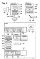
- the FIG. 1 shows a computer system 100 by which a platform for multiple participants I, II, ... is provided.
- the computer system 100 has a communication interface 102 for establishing communication links with the subscribers I, II, ... by means of a data protocol, such as TCP / IP.
- the computer system 100 has an authentication component 104 for authenticating the subscribers I, II,... To the computer system 100.
- the authentication is preferably carried out using a cryptographic protocol, in particular with the Secure Socket Layer (SSL) V3 protocol.
- SSL Secure Socket Layer
- the computer system 100 has a signature component 106 for generating an electronic signature, a verification component 108 for verifying the authenticity of an electronic signature, and an archiving component 110 for archiving data or files, such as electronic invoices, and the associated audit logs generated by the verification component 108.
- the conversion component 112 of the computer system 100 is for converting the formats of received data or files into a processing format used by the computer system 100.
- computer system 100 may receive EDIFACT, IDOC, CCG-ASCI, and / or other formats. Data of such formats are converted to a uniform format used by the computer system 100.
- this format used by computer system 100 may be a markup language format, such as an XML format.
- the conversion component 112 can also convert from the format used by the computer system 100, for example, the XML format, into various receiver formats of subscribers, who can receive data or files from the computer system.
- Such a data conversion has the advantage that, regardless of the particular data formats used by the subscriber, data exchange between the subscribers can take place via the platform or "hub" formed by the computer system 100.
- the computer system 100 further has a forwarding component 113 for forwarding data received from one of the participants to another of the participants via a specified communication medium, such as by e-mail.
- the computer system 100 may include a separate forwarding component 113 for each communication medium in question.
- the forwarding component 113 may cover various communication media.
- the computer system 100 further includes an analysis component 114 for reading information from the data or files previously converted into the format used by the computer system 100. Such read-out of information may be required for further processing or forwarding of data or files.
- the analysis component 114 is designed so that it can process data or files in the format used by the computer system 100.
- the format conversion by the conversion component 112 also has the advantage that The same analysis component 114 can be used to process data or files of different subscribers using different data formats. This greatly reduces the programming overhead for the analysis component 114.
- the computer system 100 may implement other basic functions associated with electronic legal commerce, such as a function for data compression of documents, such as a zip function.
- Each method contains at least one of the basic functions.
- a method can also include several of the basic functions that are linked together in a workflow. The concatenation can be carried out sequentially and / or in parallel.
- a method M1 provided by the computer system 100 is defined in the configuration component 116 as the sequential concatenation of the basic functions provided by the signing component 106 and the forwarding component 113.
- the method M2 which consists of a sequential concatenation of the basic functions provided by the signing component 106, the archiving component 110 and the forwarding component 113.
- the method M2 can also be defined such that after execution of the basic functions provided by the signing component 106, the following basic functions made available by the archiving component 110 or the forwarding component 113 run parallel to one another.
- the configuration component 116 includes further such definitions for the methods M3, M4, M5,..., Which are provided by the computer system 100.
- the component 116 can be maintained by an administrator to adapt it to the respective requirements, for example to define additional methods based on the given basic functions and / or to modify existing definitions.
- the methods of the computer system 100 defined in this way can be called by the participants via the communication interface 102 via the network 126.
- the methods may be part of the data protocol of the communication interface 102 or upstream or downstream.
- the communication interface 102 is implemented as a web service.
- the method calls of the subscribers are made via the web service provided by the communication interface 102, which contains these methods.
- a subscriber can himself determine which of the services provided by the computer system 100 he would like to use.
- the participant concerned passes certain parameters needed by the method to execute the corresponding service, such as a parameter to specify a file format, an identifier for the conversion, an e-mail address for forwarding, for example to a bill-to party, etc.
- a subscriber identifier of the recipient of a document can be transferred as a parameter, so that the relevant data is archived with this subscriber identifier. The subscriber concerned can then retrieve the archived data with the aid of his subscriber identifier by calling a corresponding method from the archive.
- the methods provided by the computer system 100 and the parameters required by these methods may be described in a web service WSDL document 102.
- the subscribers may download the WSDL document 102 "directly from the web service over the network 126 that the communication interface 102 provides, or query from an external directory server by means of the so-called discovery of this web service.
- the definition of the methods in the configuration component 116 is changed, eg if an additional method is defined on the basis of a corresponding customer request, an existing method is changed, or another method definition is updated, the corresponding changes are also made in the WSDL document 102 "registered.
- the administrator first enters the changes in the definition of the methods into the configuration component 116.
- these changes are automatically entered into the WSDL document 102 "so that the participants' external computer systems are aware of this change and can invoke the modified or additional methods Updating the WSDL document 102 "can also be an automatic versioning done.
- the computer system 100 may further comprise a configuration database in which subscriber profiles are stored. Each of the subscriber profiles can be accessed with an identifier ("Subscriber ID").
- Subscriber ID is, for example, a so-called primary or secondary key of the configuration database 116.
- a subscriber profile various subscriber-specific information can be stored, which then need not be passed as parameters in a method call. For example, it may be specified in a subscriber profile which data or file format the relevant subscriber requires, which is his subscriber address and / or the type of data transmission desired by the subscriber, that is, for example, electronically or in paper form.
- the FIG. 1 shows by way of example a computer system 118 of the subscriber I.
- the computer system 118 has an application program 120, such as a so-called ERP program.
- the application program 120 may generate a file 122.
- the file 122 may be, for example, an electronic invoice in the format EDIFACT.
- the computer system 118 further has a communication interface 124 through which a data protocol is realized to communicate over a network 126 the computer system 100 to be able to establish communication links.
- the network 126 may be, for example, a public network, such as the Internet, or another computer and / or telecommunications network.
- the computer system 128 of the subscriber II has an application program 130; this may also be an ERP application program, an accounting program or the like.
- the application program 130 is used to process a file 132 which has been received via a communication interface 134.
- the communication interface 134 implements a data protocol for establishing communication links with the computer system 100.
- the communication interfaces 124, 134,... Of the subscribers are designed so that the methods provided by the computer system 100 can be called up via the network 126.
- the data protocols implemented by the communication interfaces 124, 134, ... correspond to a W3C standard or another Internet standard.
- the communication interfaces 124, 134,... are designed for communication via SOAP messages in order to execute function calls of the web service of the communication interface 102 and to transmit or receive corresponding parameters and data or files.
- the actions to be performed on the file 122 are determined by the subscriber I by calling one of the methods of the computer system 100 itself.
- the necessary information e.g. the data of the receiving party, that is, for example, the subscriber II, are passed as parameters to the called method. In this procedure, the participants are absolutely flexible, since they can pass individual parameters to each call.
- the subscriber I with his computer system 118 establishes a communication connection via the communication interface 124 via the network 126 to the computer system 100, that is to its communication interface 102.
- the authentication of the subscriber I takes place, for example according to the SSLV3 protocol or another protocol or access method.
- the access succeeds eg certificate-based over HTTPS.
- the latter can direct a function call of the desired method to the web service of the computer system 100.
- the subscriber I is identified to the computer system 100.
- computer system 100 will convert file 122 by conversion component 112 into the format used by computer system 100, such as a canonical XML format convert.
- the file 122 converted to the format used by the computer system 100 is then subjected to content analysis by the analysis component 114;
- the identifier of the subscriber who is to receive the file from the subscriber I ie, for example, what is known as the International Location Number ILN, is determined by the content analysis.
- the computer system based on the authentication and the associated identification of the subscriber I with respect to the computer system 100, can access the subscriber profile of the subscriber I in the configuration database, from there parameters for the execution of the called Retrieve method.
- the file 122 converted to the format used by the computer system 100 is then converted by the conversion component 112 into the format specified in the subscriber profile of the subscriber II.
- the desired format may be specified by a unique identifier. This identifier can be defined in a previous customer-specific adaptation, the so-called customizing.
- the file 122 converted to the format of the subscriber II is then electronically signed by the signing component 106.
- the computer system 128 may further process the file 132 by means of the application program 130, for example. For this purpose, it is typically necessary that the authenticity of the electronically signed file 132 is checked by the subscriber II. To verify the authenticity of the electronically signed file 132, the subscriber II connects his computer system 128 to the computer system 100 via the network 126. Thereafter, the subscriber II is authenticated to the computer system 100 with the aid of the authentication component 104. If the subscriber II wishes to verify the files sent by subscriber I, he invokes the appropriate method M4 for this.
- connection verification by the computer system results in a considerable simplification of the workflow, since the participant II does not have to carry out the verification himself.
- the subscriber II then sends the signed file 132 from the computer system 128 to the computer system 100 via the network 126.
- the verification component 108 then checks the authenticity of the electronic signature of the file 132 and generates a corresponding check protocol.
- the file 132 is archived by the archiving component 110 together with the test protocol in accordance with the parameters of the subscriber II transferred during the method call of the method M5.
- the result of verifying the electronic signature of the file 132 may be communicated from the computer system 100 to the subscriber II via the network 126 or to another subscriber authorized thereto.
- Prior to archiving the file 132 it is preferably converted by the conversion component 112 into the data format used by the computer system 100.
- FIG. 2 shows a further embodiment. Elements of FIG. 2 , the elements of FIG. 1 are denoted by the same reference numerals.
- the computer system 118 has a signature client 136 for making electronic signatures.
- a chip card reader 138 is connected to the computer system 118.
- the private key of the subscriber I for making an electronic signature by the signature client 136 is stored on a chip card 140.
- the private key is stored on the smart card 140 as part of a so-called PSE (Personal Security Environment).
- PSE Personal Security Environment
- the PSE may be stored as an encrypted file in the computer system 118. The use of the PSE is typically password protected.
- the signing component 106 of the computer system 100 is designed to carry out a so-called mass-signature method, that is to say automated signing.
- the signing component 106 has a so-called chip card rack for accommodating a larger number of chip cards operating in parallel in order to enable a high throughput.
- the chip cards are designed so that after a single correct entry of the PIN any number of electronic signatures can be performed automatically.
- Mass signature methods are known as such from the prior art, cf. for example "Aspects of mass signature", Detlef Pühnlein, Yvonne Knosowski (http://www.secunet.de/download/fachisme/dach2003_aspekte-der-massensignatur.pdf).
- the data protocol used for communication between the computer system 100 and the computer systems 118, 128, ... is the TCP / IP protocol, such as HTTPS over port 443.
- the conversion component 112 (cf. Fig. 1
- the converter group 112 ' includes the converters 148, 150, 152, ...
- Each of these converters of the converter group 112' serves to convert a transmitter format, that is, one of the subscribers I, II in a format used by the computer system 100.
- the format used by the computer system 100 it is preferably the format of a markup language, in particular an XML format.
- the converter 148 is for converting an EDIFACT sender format into the XML format of the computer system 100, the converter 150 for converting an IDOC sender format into XML, the converter 152 for converting a CCG-ASCI sender format into XML, etc.
- a separate converter must be developed for each of these dialects in the phase of customization. Each of these converters receives its own, unique identifier. Accordingly, it is necessary to deal with different dialects of other formats (e.g., EDIFACT).
- Each of the converters 148, 150, 152,... Of the converter group 112 ' is assigned a fixed identifier.
- the identifier determines which format it is.
- the identifier is passed to the computer system 100 as a parameter of the corresponding conversion method.
- the received data is converted into the XML format (canonical XML) of the computer system 100 with the converter specified by the identifier.
- the converter group 112 "includes a plurality of converters 154, 156, 158,...
- the converter 154 is used for conversion from the XML format of the computer system 100 into EDIFACT
- the converter 156 for conversion from the XML format into the IDoc format
- the converter 158 for conversion from the XML format to CCG-ASCI, etc.
- the format conversion is also preferably initiated by a method call of a corresponding formatting method.
- the identifier of the desired converter is passed as a parameter when the method is called.
- Subscriber I determines, for example, with the aid of the called method, that an electronic document received by the subscriber I is to be signed and forwarded to a recipient specified in the electronic document or in the parameters of the method. Furthermore, the type of electronic signing can be specified in the parameters of the called method.
- the receiver format required by the subscriber II and the receiver address of the subscriber II are likewise defined in the parameters of the called method. The receiver format identifier is used to select the appropriate converter to perform the conversion method.
- the communication of the subscribers I, II,... With the computer system 100 is effected by means of a data protocol 102 'provided by the communication interface, such as e.g. SOAP.
- a file 122 generated by the application 120 of the computer system 118 includes an electronic document, such as an electronic bill. If the application 120 is an SAP system, the file 122 is typically generated in the format IDOC. The file is sent in the IDOC format by calling the corresponding method (conversion) and specifying the corresponding identifier for the conversion of the IDOC format determined during the individual adaptation phase. The identifier is given as parameter of the method (conversion). The same applies to the conversion jobs of the other users for whom converters with the corresponding identifier were also created in the customization phase.
- the file 122 is thus received by the Web service of the computer system 100 via a method call and forwarded to the converter 150, by means of which a conversion of the IDOC format into XML takes place.
- an authentication of the subscriber I to the computer system 100 is required, which is performed by the authentication component 104.
- the analysis component 114 is started to read a receiver identifier from the file 122, such as the ILN of the subscriber who is to receive the signed file.
- the XML converted file 122 is then converted into the receiver format by one of the converters 154, 156, 158, ... of the converter group 112 "If the receiver - for example, the subscriber II - requires the format EDIFACT, then the conversion for example, made by the converter 154, which corresponds to the EDIFACT dialect of the customer.
- the converted into the receiver format file 122 is then signed electronically. This is done by the computer system 100 by means of the signing component 106 in a mass signature method.
- the computer system 100 may include multiple TCP / IP ports 142, 144, 146, ....
- each of the TCP / IP ports is assigned a port number.
- TCP / IP port 142 has port number A
- TCP / IP port 144 has port number B
- TCP / IP port 146 has port number C, etc.
- the port numbers A, B, C, ... are in a number space that does not include the common port numbers.
- Commonly used port numbers include, for example, port number 23 for Telnet, port number 25 for SMTP, port number 80 for HTTP, port number 443 for HTTPS, port number 3389 for MSRemote Desktop / Terminal Services, port numbers 5631 and 5632 for pcAnywhere.
- the port numbers A, B, C, ... have at least five digits and are assigned in ascending order from the port number 50,000.
- the computer system 100 may include other common ports, such as port 80 for HTTP and port 443 for HTTPS communication.
- each of the converters 148, 150, 152, ... of the converter group 112 ' is dedicated to one of the TCP / IP ports 142, 144, 146, ....
- the converter 148 is associated with the TCP / IP port 142, the converter 150 with the TCP / IP port 144, and the converter 152 with the TCP / IP port 146, etc.
- the TCP / IP port 142 thus serves to receive EDIFACT Documents, which are then automatically converted by the TCP / IP port 142 associated converter 148 in the XML format of the computer system 100.
- TCP / IP port 144 is used to receive IDOC documents, which are then automatically converted to XML, port 146 to receive CCG ASCI documents, which are also automatically converted to XML format, etc.
- a receiver profile can be stored in the configuration database 116, which can be accessed with the identifier of the subscriber II, that is, with its "receiver ID" as a key.
- the recipient profile of the subscriber II specifies the receiver format required by the subscriber II and the receiver address of the subscriber II.
- the communication of the subscribers I, II with the computer system 100 takes place by means of a data protocol 102 'made available by the communication interface, via which the methods M1, M2, M3,... Can be called up.
- the communication interface 124 of the computer system 118 is configured here such that the file 122 is sent to the IDOC-format-assigned port of the computer system 100, that is to say to the TCP / IP port 144 with the port number B.
- the file 122 is thus received by the TCP / IP port 144 of the computer system 100 and forwarded to the converter 150, by means of which a conversion of the IDOC format into XML takes place.
- the analysis component 114 is then started to read a receiver identifier from file 122, such as the ILN of the subscriber who is to receive the signed file. With the thus obtained Recipient ID is accessed to the recipient profile of the subscriber in the configuration database 116 who is to receive the signed file 122. There, the receiver format required by the recipient is specified. The XML converted file 122 is then converted into the receiver format by one of the converters 154, 156, 158, ... of the converter group 112 "If the receiver - for example, the subscriber II - requires the format EDIFACT, then the conversion made by the converter 154.
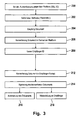
- FIG. 3 shows a corresponding flowchart, wherein the type of conversion over the method calls and not the ports is selected by the participants.
- an authentication of one of the subscribers takes place in relation to that of the computer system 100 (cf. FIGS. 1 and 2 ) provided platform.
- the authentication preferably takes place with the SSLV3 protocol (certificate-based, HTTPS).
- step 202 the desired method is called by the subscriber I.
- the subscriber I By calling the corresponding method and the parameters passed in, the subscriber I specifies, for example, that the received document should be signed, forwarded to a receiver and archived (method M1 - see. Fig. 1 . 2 and 4 ).
- a document is received from the subscriber I.
- this is converted to the format of the platform, ie the processing format.
- a receiver identifier "receiver ID" is read from the given parameters.
- the receiver format specified by the recipient and the recipient address are derived from the parameters passed when the method is called (ie step 210 is omitted).
- the document is then converted to the receiver format in step 212 and the electronic signature of the converted document is performed in step 214, either in a mass signature process by the platform or after retransmission of the converted document by the participant I itself.
- the document for subscriber I is archived. This can be done in the sender format of the subscriber I, in the receiver format of the subscriber II or in the XML format of the platform. Archiving may be done in the format of the platform or in another format desired by the participant concerned. Conveniently, it should be the format in which the valid, i. the signed invoice document is available; For this purpose, the test log is archived at the same time.
- step 218 the converted and signed document is forwarded to the receiver, that is, for example, subscriber II.
- the data may be compressed prior to archiving or forwarding.
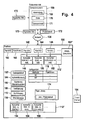
- FIG. 4 shows a further embodiment of the computer system. Elements of FIG. 4 , the elements of FIGS. 1 and 2 are denoted by the same reference numerals.
- the computer system 100 in the embodiment of the FIG. 4 In addition to TCP / IP ports 142, 144, 146, ..., each assigned to a particular sender format, it has standard ports 160 and 162 with port numbers 80 and 443 for the HTTP and HTTPS data protocols, respectively.
- the computer system 100 is connected to or includes a so-called trust center 164.
- the trust center 164 is a certification authority, for example according to the Signature Law of the Federal Republic of Germany. With the help of the trust center 164 can be checked whether the transmitted with an electronic signature certificate is valid or not.
- the FIG. 4 shows a computer system 166 of a subscriber III.
- the computer system 166 has an application program 168 and a communication interface 172 that can execute a data protocol, such as HTTP or HTTPS.
- the computer system 166 may receive a signed document 170 which is stored by the application 168 as a file.
- the subscriber III uses the computer system 100.
- the computer system 166 and the computer system 100 establishes a connection via the network 126, for example by means of HTTP or HTTPS, that is to say with the port 160 or the port 162 of the computer system 100.
- the subscriber III is first authenticated by this means. After identification and authentication of the subscriber III, the subscriber III can send a signed document to the computer system 100 by calling a desired method, for example the method M5, with the necessary parameters to check the document for its signature and the received document together with to archive the audit trail generated by the verification of the electronic signature.
- the signed document 170 and / or the unsigned document 172 are archived by the archiving component 110 along with the verification log generated during the verification.
- a so-called tape library 174 of the computer system 100 is used or another, suitable for archiving storage medium.
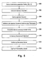
- FIG. 5 shows a corresponding flow chart.
- step 300 the authentication of the subscriber III, that is to say of the sender of the signed document, takes place in relation to the platform.
- the method called by the subscriber III is, for example, in the configuration component 116 (cf. Fig. 1 . 2 and 4 ) defines that the data received from the subscriber III is to be verified and archived.
- step 304 a signed document is received by the subscriber III from the platform.
- step 306 a verification of the electronic signature of the document and the creation of a corresponding test protocol takes place. After the verification, a conversion to a format desired by the participant III can take place, if this function belongs to the definition of the called method.
- the format desired by the participant III can be passed in the form of an identifier as a parameter in the call of the method of the participant III to the computer system or its web service.
- one of the converters of the converter group 112 "(cf. FIG. 4 ) can be used to convert a document 172 converted into the desired format (cf. FIG. 4 ) to create.
- the document and its associated audit trail are archived and the verified document is transferred, if necessary, after conversion, to the participant III in step 312.
- subscriber III may access the archived audit trail via the web interface of the platform. Such access to the test protocol can also be done by other authorized subscribers.
- FIG. 12 shows a block diagram of an embodiment of a signing component 106, as used in the embodiments of FIGS FIG. 1 . 2 and 4 can be used.
- the signing component can form one or more queues, such as those in the FIG. 6
- the queue 176 operates according to the first-in, first-out (FIFO) principle.
- the signing component 106 further includes a mass signature device 178 having, for example, a smart card rack.
- the mass-signature device 178 serves to receive, for example, a number of n chip cards Cj with 0 ⁇ j.ltoreq.n. By the consecutive number j of the chip cards, an order of the chip cards is logically defined in the exemplary embodiment considered here.
- the signing component 106 further has a scheduler 180 for assigning elements of the queue 176 to the smart cards Cj of the mass signature device 178. This allocation can be made for the dynamic load distribution between the smart cards.
- the scheduler 180 has access to status data 182 of the smart cards.
- Each of the smart cards that can process elements of the queue 176 is assigned a status using the status data 182, either a first status "free” or a second status "busy".
- the first status "free” indicates that the chip card in question is ready to receive a smart card command to generate an electronic signature for an item of the queue 176.
- the "busy" status assigned to a chip card indicates that the chip card in question is not ready to receive a chip card command with the request to generate an electronic signature for an element of the queue, which may be due to the fact that the chip card concerned is currently generating such an electronic signature is busy for a previously assigned to this smart card element of the queue.
- the chip card C1 has the status "busy”
- the chip card C2 has the status "free”
- the chip card C3 has the status "busy”
- the chip card C4 has the status "free”
- the scheduler 180 may include a timeout component 184. After the scheduler 180 has assigned an item to the queue of one of the smart cards and has addressed a corresponding smart card command to the relevant smart card, a timer of the timeout component 184 is started. After the smart card has executed the smart card command, that is, after the electronic signature has been generated, the chip card concerned responds with the output of the requested electronic signature. This will stop the timer.
- the scheduler 180 assumes that the chip card in question is at least temporarily not available for the generation of electronic signatures, because, for example, there is a technical defect.
- the chip card in question is then at least logically removed from the predetermined sequence of chip cards, so that it is basically no longer available for the allocation of elements of the queue 176. This can be done by the chip card in question is permanently set to the status "busy".
- the scheduler 180 assigns the previously assigned to this smart card element of the queue again to another chip card, which is included in the predetermined order, which therefore does not have a temporary or permanent "busy" status.
- the signing component 106 receives a request 186 Ai to generate an electronic signature for a document of one of the participants.
- the request Ai thus represents a call to the first function, that is to say the signature function.
- the request Ai is appended to the queue 176 as the last element. Once the elements of queue 176 preceding the request Ai, i. the elements A1, A2, A3, ... have been processed, the request Ail is assigned by the scheduler 180 to one of the smart cards that is currently "free".
- the scheduler 180 then sends a smart card command to the smart card C2 to generate an electronic signature according to the request Ai.
- the status of the smart card C2 in the status data 182 is updated, namely set from "free” to "busy”.
- a timer of the timeout component 184 for the chip card C2 is started.
- the smart card C2 If the smart card C2 is functioning normally, within a period of, for example, approximately one second, it issues the desired electronic signature 188 which is output from the signing component 106 to the computer system 100. If, on the other hand, the chip card C2 does not respond to the chip card command within the time period specified by the timeout component 184-for example, 1.5 seconds-with the output of the electronic signature 188, the scheduler 180 assumes that the chip card C2 is at least temporarily not is available, so that the status of the chip card C2 remains "busy" and the request Al is assigned to another chip card, which currently has the status "free", for the generation of the desired electronic signature 188. Requests following Ai follow the same procedure.
- the FIG. 7 shows an embodiment of a mass signature method according to the invention.
- the scheduler accesses the request Ai of the queue which is next in line for processing.
- the scheduler assigns this request Ai to one of the chip cards available for the desired electronic signature that have the status "free".
- the assignment of the request Ai takes place, for example, to the free chip cards in the order given by their sequence number j.
- the smart card Cj to which the request Ai has been assigned in step 402 is set to the status "busy”.
- the index i is incremented so that subsequently the next request Ai of the queue is processed.
- step 408 which proceeds asynchronously to steps 400 to 406, the scheduler receives the information "chip card free" from the chip card Cj or another chip card to which an element of the queue has previously been allocated, whereupon the scheduler receives the status of the relevant chip card from "busy” is set to "free".
- the information "smart card free” may be implied by the return of a signature by one of the smart cards, as this means that the smart card may subsequently process another element of the queue.
- first and second sets of smart cards can be defined, to each of which a queue and a scheduler are assigned.
- the chip cards of the first set are used to generate electronic signatures of a first of the participants.
- the queue associated with the first set of smart cards includes only requests originating from that first of the users.
- the second set of smart cards of the mass-signature device 178 serves to generate electronic signatures of a third party, such as the operator of the computer system 100.
- the queue associated with the second set of smart cards accordingly includes requests from various subscribers who have given power to the operator of the computer system 100 to sign the documents of these participants with the electronic signature of the operator.
- dedicated queues may also be used for certain types of electronic signatures, such as simple, advanced, or qualified mass signatures are formed, the corresponding amounts of smart cards, which can generate the particular desired type of electronic signature, are assigned.
- a method M6 for calling a workflow which includes a mass signature with the signature of a particular of the participants.
- This method M6 can therefore only be called by this subscriber after prior authentication.
- a method M7 may be defined which includes a mass signature with the electronic signature of the operator of the computer system 100.
Landscapes
- Engineering & Computer Science (AREA)
- Computer Security & Cryptography (AREA)
- Computer Hardware Design (AREA)
- Computing Systems (AREA)
- General Engineering & Computer Science (AREA)
- Computer Networks & Wireless Communication (AREA)
- Signal Processing (AREA)
- Storage Device Security (AREA)
Claims (13)
- Système informatique avec- des moyens (102 ; 102', 102") pour l'établissement de liaisons de communication avec plusieurs systèmes informatiques d'abonnés externes (118, 128 ; 166) de plusieurs abonnés,- des moyens (106) pour la signature de données reçues par l'un des systèmes informatiques d'abonnés externes, par une première fonction, les moyens pour la signature de données étant conçus pour l'exécution d'un procédé de signature en masse parallélisé,- des moyens (176, 180) pour la répartition de charge dynamique entre plusieurs cartes à puce prévues pour générer les signatures électroniques,- des moyens (108) pour la vérification d'une signature électronique relative à des données reçues par l'un des systèmes informatiques d'abonnés externes, par une deuxième fonction,- des moyens pour la transmission de données reçues par l'un des systèmes informatiques d'abonnés externes à un autre parmi les systèmes informatiques d'abonnés externes, par des liaisons de communication, par une quatrième fonction,- des moyens (116) pour la mise à disposition de méthodes (M1, M2, M3, ...), où chacune des méthodes est définie par au moins l'une des première à quatrième fonctions ou par une concaténation séquentielle et/ou parallèle de plusieurs parmi première à quatrième fonctions, et où au moins quelques-unes parmi les méthodes contiennent plusieurs des première à quatrième fonctions,- des moyens permettant une utilisation des méthodes par les systèmes informatiques d'abonnés externes, par les liaisons de communication,- des moyens (104) pour l'authentification des abonnés et/ou des systèmes informatiques d'abonnés externes, les moyens pour l'authentification étant conçus pour l'exécution d'un protocole cryptographique à l'aide d'un certificat,
dans lequel l'utilisation de l'une des méthodes par l'un des systèmes informatiques d'abonnés externes suppose l'authentification préalable de l'abonné à ce système informatique d'abonné externe et/ou du système informatique d'abonné externe vis-à-vis du système informatique. - Système informatique selon la revendication 1, avec des moyens (112 ; 112', 112") pour la conversion de données d'un format d'expéditeur d'un premier abonné vers un format du système informatique, et pour la conversion des données du format du système informatique vers un format de destinataire d'un deuxième abonné.
- Système informatique selon la revendication 2, dans lequel les moyens pour la conversion peuvent être appelés par des méthodes, et dans lequel les moyens pour la conversion peuvent être configurés spécifiquement pour chaque abonné et appelés par l'abonné concerné en tant que méthodes spécifiques à un abonné, à l'aide d'un identificateur d'abonné correspondant.
- Système informatique selon l'une des revendications précédentes, avec un service internet, dans lequel le service internet contient les méthodes, dans lequel le service internet contient un document WSDL contenant une description des méthodes et de leurs paramètres, dans lequel le document WSDL est accessible aux abonnés par les liaisons de communication, dans lequel un document WSDL du service internet contenant une description des méthodes et de leurs paramètres est enregistré dans un répertoire externe, à partir duquel il est accessible aux abonnés par un réseau public.
- Système informatique selon la revendication 4, dans lequel les moyens pour la signature comportent des moyens de file d'attente (176) destinés à former une file d'attente pour l'exécution de recours à la première fonction sur la base du recours à des méthodes correspondantes contenant la première fonction, et avec un dispositif de signature en masse (176) avec plusieurs cartes à puce, chacune des cartes à puce étant conçue pour générer une signature électronique, et avec des moyens de planification (180) pour l'attribution d'un élément de la file d'attente dont le tour est arrivé à l'une des cartes à puce.
- Système informatique selon la revendication 5, dans lequel un ordre de succession prédéterminé est défini pour les cartes à puce, et dans lequel chaque carte à puce a un premier ou un deuxième statut, dans lequel la carte à puce ne peut traiter un élément de la file d'attente qu'avec le premier statut pour générer une signature électronique, et dans lequel les moyens de planification sont conçus de telle façon, qu'un élément de la file d'attente dont le tour est arrivé est attribué à l'une des cartes à puce ayant le premier statut, selon l'ordre de succession prédéterminé de la carte à puce.
- Système informatique selon la revendication 6, dans lequel les moyens de planification possèdent un composant de temps limite (184) conçu de manière à ce qu'une carte à puce gardant le deuxième statut au-delà d'une durée prédéterminée soit éliminée de l'ordre de succession des cartes à puce, et à ce qu'un élément de la file d'attente auparavant attribué à cette carte à puce soit réattribué par les moyens de planification à l'une des cartes à puce encore présentes dans l'ordre de succession prédéterminé.
- Système informatique selon l'une des revendications précédentes, avec des moyens pour la conversion des données reçues par un abonné vers un format de langage de balisage, et pour la conversion des données du format du langage de balisage vers un format de destinataire, dans lequel le format du langage de balisage sert de format de traitement.
- Procédé pour la signature, la vérification de signature, l'archivage et/ou la transmission de données au moyen d'un système informatique, dans lequel le système informatique comporte une interface pour l'établissement de liaisons de communication avec plusieurs abonnés, et dans lequel des méthodes du système informatique sont accessibles aux abonnés par l'interface, dans lequel chacune des méthodes est définie au moins par une fonction pour la signature, la vérification de signature, l'archivage et/ou la transmission de données, ou encore par une concaténation séquentielle ou parallèle de telles fonctions, avec les étapes suivantes :- établissement d'une liaison de communication de l'un des abonnés avec le système informatique pour la réception de données de l'abonné,- exécution d'une méthode appelée par l'abonné,- dans lequel la signature est réalisée par un procédé de signature en masse parallélisé, dans lequel une répartition de charge dynamique a lieu entre plusieurs cartes à puce d'un dispositif de signature en masse (178), dans lequel chacune des cartes à puce est conçue pour générer une signature électronique.
- Procédé selon la revendication 9, dans lequel les données reçues par l'un des abonnés sont converties dans le format d'un langage de balisage, et/ou dans lequel les données sont reçues sur un port du système informatique attribué au format des données.
- Procédé selon la revendication 10, dans lequel le procédé de signature de masse parallélisé contient les étapes suivantes :- formation d'une file d'attente pour l'exécution des premières fonctions sur la base du recours à des méthodes correspondantes contenant la première fonction,- attribution de l'élément de la file d'attente dont le tour est arrivé à une carte à puce du dispositif de signature de masse (178) contenant plusieurs cartes à puce.
- Procédé selon la revendication 11, dans lequel un ordre de succession prédéterminé est défini pour les cartes à puce, et dans lequel chaque carte à puce a un premier ou un deuxième statut, dans lequel chaque carte à puce ne peut traiter un élément de la file d'attente qui lui est attribué qu'avec le premier statut pour générer une signature électronique, et dans lequel l'attribution d'un élément de la file d'attente dont le tour est arrivé est effectuée de manière à ce que l'attribution de cet élément à une carte à puce ayant le premier statut se fasse dans un ordre de succession de cartes à puce prédéterminé, et dans lequel une carte à puce gardant le deuxième statut au-delà d'une durée prédéterminée est de préférence éliminée de l'ordre de succession des cartes à puce, et dans lequel un élément de la file d'attente auparavant attribué à cette carte à puce est de préférence réattribué à l'une des cartes à puce encore présentes dans l'ordre de succession prédéterminé, et/ou dans lequel une première file d'attente ne contenant que des appels de première fonction d'un premier abonné est formée pour le premier abonné, et dans lequel une deuxième file d'attente commune contenant les appels de première fonction de plusieurs deuxièmes abonnés est formée pour les deuxièmes abonnés.
- Produit de programme informatique, en particulier un moyen de stockage numérique, avec des instructions exécutables par ordinateur, pour l'exécution d'un procédé selon l'une des revendications 9 à 12.
Priority Applications (1)
| Application Number | Priority Date | Filing Date | Title |
|---|---|---|---|
| PL07820143T PL2067341T3 (pl) | 2006-09-12 | 2007-09-12 | System komputerowy i sposób sygnowania, weryfikacji sygnatur i/lub archiwizacji |
Applications Claiming Priority (2)
| Application Number | Priority Date | Filing Date | Title |
|---|---|---|---|
| DE102006043497A DE102006043497A1 (de) | 2006-09-12 | 2006-09-12 | Computersystem und Verfahren zur Signierung, Signaturverifizierung und/oder Archivierung |
| PCT/EP2007/059572 WO2008031840A1 (fr) | 2006-09-12 | 2007-09-12 | Système informatique et procédé de signature, de vérification de signature et/ou d'archivage |
Publications (2)
| Publication Number | Publication Date |
|---|---|
| EP2067341A1 EP2067341A1 (fr) | 2009-06-10 |
| EP2067341B1 true EP2067341B1 (fr) | 2013-11-06 |
Family
ID=38982512
Family Applications (1)
| Application Number | Title | Priority Date | Filing Date |
|---|---|---|---|
| EP07820143.1A Active EP2067341B1 (fr) | 2006-09-12 | 2007-09-12 | Système informatique et procédé de signature, de vérification de signature et/ou d'archivage |
Country Status (5)
| Country | Link |
|---|---|
| EP (1) | EP2067341B1 (fr) |
| DE (1) | DE102006043497A1 (fr) |
| ES (1) | ES2440250T3 (fr) |
| PL (1) | PL2067341T3 (fr) |
| WO (1) | WO2008031840A1 (fr) |
Families Citing this family (2)
| Publication number | Priority date | Publication date | Assignee | Title |
|---|---|---|---|---|
| DE102011053658A1 (de) | 2011-09-15 | 2013-03-21 | Tim Meyer-Dulheuer | Rechnungs- und Quittungssystem für rechtssicheres Archivieren elektronischer Belege |
| CN114491462B (zh) * | 2022-02-10 | 2023-07-18 | 重庆傲雄在线信息技术有限公司 | 单次签署多份电子文件的方法、系统、设备及存储介质 |
Family Cites Families (6)
| Publication number | Priority date | Publication date | Assignee | Title |
|---|---|---|---|---|
| US6584466B1 (en) * | 1999-04-07 | 2003-06-24 | Critical Path, Inc. | Internet document management system and methods |
| US6289460B1 (en) * | 1999-09-13 | 2001-09-11 | Astus Corporation | Document management system |
| US7237114B1 (en) | 2000-04-26 | 2007-06-26 | Pronvest, Inc. | Method and system for signing and authenticating electronic documents |
| GB0119629D0 (en) | 2001-08-10 | 2001-10-03 | Cryptomathic As | Data certification method and apparatus |
| US20050216522A1 (en) * | 2004-03-23 | 2005-09-29 | Integrated Data Corporation | Multi-tier document management system |
| DE102005011166A1 (de) * | 2005-03-09 | 2006-09-14 | Bundesdruckerei Gmbh | Computersystem und Verfahren zur Signierung, Signaturverifizierung und/oder Archivierung |
-
2006
- 2006-09-12 DE DE102006043497A patent/DE102006043497A1/de not_active Withdrawn
-
2007
- 2007-09-12 WO PCT/EP2007/059572 patent/WO2008031840A1/fr not_active Ceased
- 2007-09-12 PL PL07820143T patent/PL2067341T3/pl unknown
- 2007-09-12 EP EP07820143.1A patent/EP2067341B1/fr active Active
- 2007-09-12 ES ES07820143.1T patent/ES2440250T3/es active Active
Also Published As
| Publication number | Publication date |
|---|---|
| WO2008031840A1 (fr) | 2008-03-20 |
| DE102006043497A1 (de) | 2008-03-27 |
| PL2067341T3 (pl) | 2014-03-31 |
| ES2440250T3 (es) | 2014-01-28 |
| EP2067341A1 (fr) | 2009-06-10 |
Similar Documents
| Publication | Publication Date | Title |
|---|---|---|
| DE60200451T2 (de) | Herstellung einer gesicherten Verbindung mit einem privaten Unternehmensnetz über ein öffentliches Netz | |
| EP3033855B1 (fr) | Assistance à un déchiffrement de données chiffrées | |
| DE112011103172T5 (de) | Unterstützung des transaktionsorientierten Nachrichtenaustauschs in verbundenen Nachrichtenaustauschnetzwerken | |
| DE112011102224B4 (de) | Identitätsvermittlung zwischen Client- und Server-Anwendungen | |
| DE102008028701A1 (de) | Verfahren und System zum Erzeugen einer abgeleiteten elektronischen Identität aus einer elektronischen Hauptidentität | |
| EP2067341B1 (fr) | Système informatique et procédé de signature, de vérification de signature et/ou d'archivage | |
| EP2919145B1 (fr) | Dispositif d'authentification, système d'authentification et procédé d'authentification | |
| EP1701282A1 (fr) | Système informatique et procédé pour la signature, la vérification de signature et/ou l'archivage | |
| EP1625467B1 (fr) | Transmission electronique de documents | |
| EP2915304B1 (fr) | Procédé et système d'accès à des données dans un système de réseau distribué | |
| WO2011000608A1 (fr) | Dispositifs et procédé pour établir et valider un certificat numérique | |
| EP1183847B1 (fr) | Procede de transmission securisee de donnees protegees | |
| EP1902562B1 (fr) | Procede d'envoi et d'archivage de documents numeriques | |
| EP4430468B1 (fr) | Gestion flexible de ressources pour de multiples utilisateurs | |
| DE102005061632B4 (de) | Verfahren und Vorrichtung zur Autorisierung | |
| EP2118788B1 (fr) | Système de traitement de données et procédé de réception de données de personnalisation | |
| EP2439900B1 (fr) | Procédé et dispositif destinés à l'authentification | |
| EP4280139A1 (fr) | Système de communication, procédé et produit de programme informatique pour fournir des documents d'un ou plusieurs émetteurs à au moins un récepteur | |
| DE102016207635A1 (de) | Verfahren und Vorrichtung zur Absicherung von Gerätezugriffen | |
| DE102020116354A1 (de) | Datenbank, Abfragevorrichtung und System | |
| DE102020215817A1 (de) | Verfahren und Vorrichtung zum Verwalten eines Dienstes in einem dezentralen Transaktionssystem | |
| EP2410702A1 (fr) | Procédé de transmission d'une information électronique à travers un système de communication et système de communication correspondant | |
| DE102009037436A1 (de) | Verfahren und System zum Zugreifen von einer Vorrichtung auf zumindest einen Rechner eines Rechnerverbundes | |
| EP2720169A1 (fr) | Système et procédé de libération d'une connexion de données entre un terminal et une passerelle d'un serveur de courrier électronique | |
| Trensch | Linux-Zugang mit Benutzer-Authentisierung |
Legal Events
| Date | Code | Title | Description |
|---|---|---|---|
| PUAI | Public reference made under article 153(3) epc to a published international application that has entered the european phase |
Free format text: ORIGINAL CODE: 0009012 |
|
| 17P | Request for examination filed |
Effective date: 20090414 |
|
| AK | Designated contracting states |
Kind code of ref document: A1 Designated state(s): AT BE BG CH CY CZ DE DK EE ES FI FR GB GR HU IE IS IT LI LT LU LV MC MT NL PL PT RO SE SI SK TR |
|
| AX | Request for extension of the european patent |
Extension state: AL BA HR MK RS |
|
| 17Q | First examination report despatched |
Effective date: 20110526 |
|
| DAX | Request for extension of the european patent (deleted) | ||
| GRAP | Despatch of communication of intention to grant a patent |
Free format text: ORIGINAL CODE: EPIDOSNIGR1 |
|
| INTG | Intention to grant announced |
Effective date: 20130429 |
|
| GRAS | Grant fee paid |
Free format text: ORIGINAL CODE: EPIDOSNIGR3 |
|
| GRAA | (expected) grant |
Free format text: ORIGINAL CODE: 0009210 |
|
| AK | Designated contracting states |
Kind code of ref document: B1 Designated state(s): AT BE BG CH CY CZ DE DK EE ES FI FR GB GR HU IE IS IT LI LT LU LV MC MT NL PL PT RO SE SI SK TR |
|
| REG | Reference to a national code |
Ref country code: GB Ref legal event code: FG4D Free format text: NOT ENGLISH |
|
| REG | Reference to a national code |
Ref country code: CH Ref legal event code: EP |
|
| REG | Reference to a national code |
Ref country code: AT Ref legal event code: REF Ref document number: 640065 Country of ref document: AT Kind code of ref document: T Effective date: 20131215 |
|
| REG | Reference to a national code |
Ref country code: IE Ref legal event code: FG4D Free format text: LANGUAGE OF EP DOCUMENT: GERMAN |
|
| REG | Reference to a national code |
Ref country code: NL Ref legal event code: T3 |
|
| REG | Reference to a national code |
Ref country code: DE Ref legal event code: R096 Ref document number: 502007012485 Country of ref document: DE Effective date: 20140102 |
|
| REG | Reference to a national code |
Ref country code: ES Ref legal event code: FG2A Ref document number: 2440250 Country of ref document: ES Kind code of ref document: T3 Effective date: 20140128 Ref country code: SE Ref legal event code: TRGR |
|
| REG | Reference to a national code |
Ref country code: LT Ref legal event code: MG4D |
|
| PG25 | Lapsed in a contracting state [announced via postgrant information from national office to epo] |
Ref country code: IS Free format text: LAPSE BECAUSE OF FAILURE TO SUBMIT A TRANSLATION OF THE DESCRIPTION OR TO PAY THE FEE WITHIN THE PRESCRIBED TIME-LIMIT Effective date: 20140306 Ref country code: LT Free format text: LAPSE BECAUSE OF FAILURE TO SUBMIT A TRANSLATION OF THE DESCRIPTION OR TO PAY THE FEE WITHIN THE PRESCRIBED TIME-LIMIT Effective date: 20131106 |
|
| PG25 | Lapsed in a contracting state [announced via postgrant information from national office to epo] |
Ref country code: LV Free format text: LAPSE BECAUSE OF FAILURE TO SUBMIT A TRANSLATION OF THE DESCRIPTION OR TO PAY THE FEE WITHIN THE PRESCRIBED TIME-LIMIT Effective date: 20131106 |
|
| PG25 | Lapsed in a contracting state [announced via postgrant information from national office to epo] |
Ref country code: PT Free format text: LAPSE BECAUSE OF FAILURE TO SUBMIT A TRANSLATION OF THE DESCRIPTION OR TO PAY THE FEE WITHIN THE PRESCRIBED TIME-LIMIT Effective date: 20140306 |
|
| PG25 | Lapsed in a contracting state [announced via postgrant information from national office to epo] |
Ref country code: EE Free format text: LAPSE BECAUSE OF FAILURE TO SUBMIT A TRANSLATION OF THE DESCRIPTION OR TO PAY THE FEE WITHIN THE PRESCRIBED TIME-LIMIT Effective date: 20131106 |
|
| REG | Reference to a national code |
Ref country code: DE Ref legal event code: R097 Ref document number: 502007012485 Country of ref document: DE |
|
| PG25 | Lapsed in a contracting state [announced via postgrant information from national office to epo] |
Ref country code: SK Free format text: LAPSE BECAUSE OF FAILURE TO SUBMIT A TRANSLATION OF THE DESCRIPTION OR TO PAY THE FEE WITHIN THE PRESCRIBED TIME-LIMIT Effective date: 20131106 Ref country code: RO Free format text: LAPSE BECAUSE OF FAILURE TO SUBMIT A TRANSLATION OF THE DESCRIPTION OR TO PAY THE FEE WITHIN THE PRESCRIBED TIME-LIMIT Effective date: 20131106 Ref country code: CZ Free format text: LAPSE BECAUSE OF FAILURE TO SUBMIT A TRANSLATION OF THE DESCRIPTION OR TO PAY THE FEE WITHIN THE PRESCRIBED TIME-LIMIT Effective date: 20131106 |
|
| PLBE | No opposition filed within time limit |
Free format text: ORIGINAL CODE: 0009261 |
|
| STAA | Information on the status of an ep patent application or granted ep patent |
Free format text: STATUS: NO OPPOSITION FILED WITHIN TIME LIMIT |
|
| PG25 | Lapsed in a contracting state [announced via postgrant information from national office to epo] |
Ref country code: DK Free format text: LAPSE BECAUSE OF FAILURE TO SUBMIT A TRANSLATION OF THE DESCRIPTION OR TO PAY THE FEE WITHIN THE PRESCRIBED TIME-LIMIT Effective date: 20131106 |
|
| 26N | No opposition filed |
Effective date: 20140807 |
|
| REG | Reference to a national code |
Ref country code: DE Ref legal event code: R097 Ref document number: 502007012485 Country of ref document: DE Effective date: 20140807 |
|
| PG25 | Lapsed in a contracting state [announced via postgrant information from national office to epo] |
Ref country code: SI Free format text: LAPSE BECAUSE OF FAILURE TO SUBMIT A TRANSLATION OF THE DESCRIPTION OR TO PAY THE FEE WITHIN THE PRESCRIBED TIME-LIMIT Effective date: 20131106 |
|
| PG25 | Lapsed in a contracting state [announced via postgrant information from national office to epo] |
Ref country code: LU Free format text: LAPSE BECAUSE OF FAILURE TO SUBMIT A TRANSLATION OF THE DESCRIPTION OR TO PAY THE FEE WITHIN THE PRESCRIBED TIME-LIMIT Effective date: 20140912 Ref country code: MC Free format text: LAPSE BECAUSE OF FAILURE TO SUBMIT A TRANSLATION OF THE DESCRIPTION OR TO PAY THE FEE WITHIN THE PRESCRIBED TIME-LIMIT Effective date: 20131106 |
|
| REG | Reference to a national code |
Ref country code: CH Ref legal event code: PL |
|
| REG | Reference to a national code |
Ref country code: IE Ref legal event code: MM4A |
|
| REG | Reference to a national code |
Ref country code: FR Ref legal event code: ST Effective date: 20150529 |
|
| PG25 | Lapsed in a contracting state [announced via postgrant information from national office to epo] |
Ref country code: BE Free format text: LAPSE BECAUSE OF NON-PAYMENT OF DUE FEES Effective date: 20140930 |
|
| PG25 | Lapsed in a contracting state [announced via postgrant information from national office to epo] |
Ref country code: LI Free format text: LAPSE BECAUSE OF NON-PAYMENT OF DUE FEES Effective date: 20140930 Ref country code: CH Free format text: LAPSE BECAUSE OF NON-PAYMENT OF DUE FEES Effective date: 20140930 |
|
| PG25 | Lapsed in a contracting state [announced via postgrant information from national office to epo] |
Ref country code: IE Free format text: LAPSE BECAUSE OF NON-PAYMENT OF DUE FEES Effective date: 20140912 Ref country code: FR Free format text: LAPSE BECAUSE OF NON-PAYMENT OF DUE FEES Effective date: 20140930 |
|
| PG25 | Lapsed in a contracting state [announced via postgrant information from national office to epo] |
Ref country code: BG Free format text: LAPSE BECAUSE OF FAILURE TO SUBMIT A TRANSLATION OF THE DESCRIPTION OR TO PAY THE FEE WITHIN THE PRESCRIBED TIME-LIMIT Effective date: 20131106 |
|
| PG25 | Lapsed in a contracting state [announced via postgrant information from national office to epo] |
Ref country code: GR Free format text: LAPSE BECAUSE OF FAILURE TO SUBMIT A TRANSLATION OF THE DESCRIPTION OR TO PAY THE FEE WITHIN THE PRESCRIBED TIME-LIMIT Effective date: 20140207 Ref country code: CY Free format text: LAPSE BECAUSE OF FAILURE TO SUBMIT A TRANSLATION OF THE DESCRIPTION OR TO PAY THE FEE WITHIN THE PRESCRIBED TIME-LIMIT Effective date: 20131106 Ref country code: MT Free format text: LAPSE BECAUSE OF FAILURE TO SUBMIT A TRANSLATION OF THE DESCRIPTION OR TO PAY THE FEE WITHIN THE PRESCRIBED TIME-LIMIT Effective date: 20131106 |
|
| PG25 | Lapsed in a contracting state [announced via postgrant information from national office to epo] |
Ref country code: HU Free format text: LAPSE BECAUSE OF FAILURE TO SUBMIT A TRANSLATION OF THE DESCRIPTION OR TO PAY THE FEE WITHIN THE PRESCRIBED TIME-LIMIT; INVALID AB INITIO Effective date: 20070912 Ref country code: TR Free format text: LAPSE BECAUSE OF FAILURE TO SUBMIT A TRANSLATION OF THE DESCRIPTION OR TO PAY THE FEE WITHIN THE PRESCRIBED TIME-LIMIT Effective date: 20131106 |
|
| REG | Reference to a national code |
Ref country code: DE Ref legal event code: R079 Ref document number: 502007012485 Country of ref document: DE Free format text: PREVIOUS MAIN CLASS: H04L0029060000 Ipc: H04L0065000000 |
|
| P01 | Opt-out of the competence of the unified patent court (upc) registered |
Effective date: 20230526 |
|
| PGFP | Annual fee paid to national office [announced via postgrant information from national office to epo] |
Ref country code: FI Payment date: 20250922 Year of fee payment: 19 |
|
| PGFP | Annual fee paid to national office [announced via postgrant information from national office to epo] |
Ref country code: DE Payment date: 20250919 Year of fee payment: 19 |
|
| PGFP | Annual fee paid to national office [announced via postgrant information from national office to epo] |
Ref country code: NL Payment date: 20250922 Year of fee payment: 19 |
|
| PGFP | Annual fee paid to national office [announced via postgrant information from national office to epo] |
Ref country code: GB Payment date: 20250923 Year of fee payment: 19 |
|
| PGFP | Annual fee paid to national office [announced via postgrant information from national office to epo] |
Ref country code: AT Payment date: 20250918 Year of fee payment: 19 |
|
| PGFP | Annual fee paid to national office [announced via postgrant information from national office to epo] |
Ref country code: SE Payment date: 20250922 Year of fee payment: 19 |
|
| PGFP | Annual fee paid to national office [announced via postgrant information from national office to epo] |
Ref country code: IT Payment date: 20250930 Year of fee payment: 19 |
|
| PGFP | Annual fee paid to national office [announced via postgrant information from national office to epo] |
Ref country code: ES Payment date: 20251020 Year of fee payment: 19 |
|
| PGFP | Annual fee paid to national office [announced via postgrant information from national office to epo] |
Ref country code: PL Payment date: 20250829 Year of fee payment: 19 |