EP2067510A1 - Balançoire familiale - Google Patents
Balançoire familiale Download PDFInfo
- Publication number
- EP2067510A1 EP2067510A1 EP08170543A EP08170543A EP2067510A1 EP 2067510 A1 EP2067510 A1 EP 2067510A1 EP 08170543 A EP08170543 A EP 08170543A EP 08170543 A EP08170543 A EP 08170543A EP 2067510 A1 EP2067510 A1 EP 2067510A1
- Authority
- EP
- European Patent Office
- Prior art keywords
- seat
- swing
- seat portion
- swing seat
- player
- Prior art date
- Legal status (The legal status is an assumption and is not a legal conclusion. Google has not performed a legal analysis and makes no representation as to the accuracy of the status listed.)
- Withdrawn
Links
- 230000000694 effects Effects 0.000 description 2
- 240000004752 Laburnum anagyroides Species 0.000 description 1
- 208000027418 Wounds and injury Diseases 0.000 description 1
- 230000001133 acceleration Effects 0.000 description 1
- 238000005452 bending Methods 0.000 description 1
- 230000001149 cognitive effect Effects 0.000 description 1
- 230000006835 compression Effects 0.000 description 1
- 238000007906 compression Methods 0.000 description 1
- 238000010276 construction Methods 0.000 description 1
- 230000006378 damage Effects 0.000 description 1
- 238000006073 displacement reaction Methods 0.000 description 1
- 238000005516 engineering process Methods 0.000 description 1
- 210000001145 finger joint Anatomy 0.000 description 1
- 230000006870 function Effects 0.000 description 1
- 238000009863 impact test Methods 0.000 description 1
- 208000014674 injury Diseases 0.000 description 1
- 238000009434 installation Methods 0.000 description 1
- 238000000034 method Methods 0.000 description 1
- 230000008450 motivation Effects 0.000 description 1
- 230000001095 motoneuron effect Effects 0.000 description 1
- 210000003739 neck Anatomy 0.000 description 1
- GOLXNESZZPUPJE-UHFFFAOYSA-N spiromesifen Chemical compound CC1=CC(C)=CC(C)=C1C(C(O1)=O)=C(OC(=O)CC(C)(C)C)C11CCCC1 GOLXNESZZPUPJE-UHFFFAOYSA-N 0.000 description 1
Images


Classifications
-
- A—HUMAN NECESSITIES
- A63—SPORTS; GAMES; AMUSEMENTS
- A63G—MERRY-GO-ROUNDS; SWINGS; ROCKING-HORSES; CHUTES; SWITCHBACKS; SIMILAR DEVICES FOR PUBLIC AMUSEMENT
- A63G9/00—Swings
Definitions
- the invention concerns the technology of mechanical playground appliances. Especially the invention concerns seat structures for swings that enable a number of persons to swing together.
- Swinging is one of the most traditional playground games.
- the required equipment is simple, it is easy to make the swing relatively safe and mechanically reliable, and the excitement generated by the dynamic movement and the feeling of weightlessness appeal to young and old players alike.
- a playground is understood to be a place equipped for activities that aim at cognitive, motoric and social development and education through an attractive and amusing way.
- An amusement park is not a playground, because it only aims at producing experiences of amusement and excitement without said educational function.
- An amusement park is always built for occasional visits, manned with personnel, and subject to charge.
- a playground is nearly always unmanned and freely accessible for regular visits by players.
- the rides are typically so wild that careful security measures under the constant supervision of trained personnel must be applied to avoid serious injury or death.
- Playground equipment is built for inherent security, enabling even very small children to play and explore relatively independently.
- playground may be defined to be a place equipped with playthings that obey the appropriate standards, which in Europe means a standard known as EN 1176 for equipment and another known as EN 1177 for materials. Other standardisation domains have their own, comparable standards about playground equipment.
- Fig. 1 illustrates schematically a known playground swing. Shown on the right in the drawing is a swing with an ordinary seat 101. For the safety of very small children it is common to use a safety seat 102.
- Safety seats come in numerous different shapes and designs but they typically comprise at least a lower part 103 for the child to sit on and a ring part 104 supported above the lower part 103 to keep the child from falling sideways from the sitting position.
- a support frame typically comprising one or more vertical support beams 105 and a horizontal support beam 106, is used to hang the swing seats freely so that swinging back and forth becomes possible.
- Pliable supports such as cords or chains 107, or in some case rigid poles, are used to hang the swing seats 101 and 102 from the horizontal support beam.
- Hinged joints are typically used at the upper ends of said pliable supports, and are necessary especially if rigid poles are used.
- the lower ends of the cords or chains 107 may have two or more branches (not shown) attached to different locations (like front edge - rear edge) of the seat.
- An objective of the invention is to provide a playground swing that motivates and enables smaller and larger players to enjoy swinging with shared amusement and joy. Another objective of the invention is to enhance the safety of small children during swinging. Yet another objective of the invention is to mitigate and avoid problems and drawbacks typical to prior art playground swings.
- the objectives of the invention are achieved by providing a combination seat for a swing, on which combination seat at least two players can sit and swing together.
- a swing seat according to the invention comprises a first seat portion, a first hanging point and a second hanging point.
- the first hanging point is located at a distance from said second hanging point in a longitudinal direction of the swing seat, thus defining a swinging direction that is perpendicular to said longitudinal direction of the swing seat.
- the swing seat is characterized in that:
- a playground swing comprises a swing seat with a first seat portion, a support frame, a first vertical support connecting a first hanging point of the swing seat to the support frame, and a second vertical support connecting a second hanging point of the swing seat to the support frame.
- the first vertical support is located at a distance from said second vertical support in a longitudinal direction of the swing seat, thus defining a swinging direction that is perpendicular to said longitudinal direction of the swing seat.
- a combination seat which comprises sitting places or seat portions for at least two players.
- the combination seat may comprise for example at least one safety seat and at least one ordinary seat, or it may comprise a number of ordinary seats in a row.
- safety seat means a swing seat or seat portion that comprises a lower part and a ring part or other support means supported above the lower part to keep a child sitting on the lower part from falling sideways from the sitting position.
- ordinary seat means a swing seat or seat portion that has a sitting part dimensioned so that a player may sit on it and swing regardless of whether the player is of the size of a child or of the size of an adult.
- the combination seat also comprises hanging points for allowing it to hang from a support structure above it, suspended by pliable supports, such as cords or chains, or rigid poles with hinged joints allowing a swinging movement.
- pliable supports such as cords or chains
- rigid poles with hinged joints allowing a swinging movement.
- a larger player such as an adult, may sit or otherwise place him- or herself onto the ordinary swing seat, while a smaller player, such as a small child, is placed into the safety seat.
- Each seat portion is formed to offer a sitting position for a player, with a front direction of a player sitting in the sitting position being parallel with the back-and-forth swinging direction.
- the smaller and larger player may then enjoy the thrill and excitement of swinging together, facing e.g. the same direction or opposite directions.
- the larger player remains constantly very close to the smaller player during the swinging movement, so that he or she may control the actions of the smaller player and ensure safety even in sudden surprising situations.
- the combination seat may be a single mechanical entity manufactured especially for this purpose.
- Fig. 2 illustrates a playground swing according to an embodiment of the invention.
- This swing can also be called a family swing, because it accommodates at least one adult or large player together with two small children.
- the swing seat is a combination seat, and can be conceptually divided into an ordinary seat portion 201 in the middle and a safety seat portion 202 at each end of the ordinary seat portion 201.
- a first mechanical part of the combination seat is a lower part 203, which in this exemplary embodiment has a plank-like elongated form which defines the longitudinal direction 204 of the swing seat. Said longitudinal direction is horizontal and perpendicular against the principal swinging direction, which is illustrated with arrows 205 and 206.
- each end of the lower part 203 is a ring part 104, so that in each case the ring part and the portion of the lower part 203 directly below it together constitute a safety seat portion 202.
- the middle portion of the lower part 203 which is not directly below any of the ring parts 104, constitutes the ordinary seat portion 201.
- a safety seat portion 202 is formed to offer a sitting position for a player, with the front direction of the player facing the direction of either arrow 205 or arrow 206. This is accomplished typically by making the ring part 104 wider sideways (i.e. in the longitudinal direction 204 of the swing seat), and by placing the supports that join the lower part and the ring part so that the player's legs naturally come pointing obliquely forward in the sitting position.
- An ordinary seat portion 201 offers more versatility, but it too is formed to offer for a player the most natural sitting position so that the front direction of the player is parallel with the swinging direction.
- the exact form and structure of the support means are not of importance to the present invention, as long as the support means enable swinging the swing seat in the principal swinging direction, i.e. direction of arrows 205 and 206, around an axis of rotation 207 that is conceptually located at or very close to the horizontal support beam 106.
- Small children sitting in a safety seat do not necessarily need any chains or other vertical supports on both sides, so in the structure of fig. 2 the rightmost and leftmost chains could be left out.
- all seat portions in swing seats according to embodiments of the invention are separated from each other by hanging points located between them, and there are hanging points also at the ends of the swing seat.
- each of the first, second and third seat portions is located between hanging points so that there is one hanging point on each side of each seat portion.
- a support typically pliable, e.g. chain
- Placing a hanging point between seat portions also helps in making the structure sturdy enough and mechanically stabile.
- the structure shown in fig. 2 must have certain characteristics. A natural requirement is that the material strength of all components must be sufficient to withstand normal use for swinging.
- the minimum ground clearance between the seat and ground is defined so that it must be 350 millimetres, except for tyre seats for which it is 400 millimetres.
- the seat of fig. 2 is not a tyre seat, so the former number is applicable. In impact testing the seat shall not give rise to peak values of acceleration greater than 50g and average surface compression shall not exceed 90N/m.
- fig. 2 only shows the combination seat alone in the support frame, in principle it is possible to use it together with other swing seats in the same frame, as long as the minimum space between seats is calculated according to the standard, taking the beam height into account.
- Fig. 3 illustrates a way of using a combining part according to an embodiment of the invention to produce a swing seat according to an embodiment of the invention.
- the two seat portions at the extremities of the swing seat are constituted of individual swing seats that could also be used as such like in prior art swings.
- the structure of fig. 3 comprises two safety seat portions 301 and 302, which can be made of known safety seats by providing suitable attachments, and a combining part 303 fixedly attached to both safety seats so that it constitutes a kind of a flat bridge between them.
- the attachment is made with fasteners 304, which can be any type of suitable mechanical fasteners.
- the combining part 303 forms an ordinary swing seat portion for an adult or larger child who can thus swing together with one or two smaller children. Depending on the length of the combining part 303 also e.g. two middle-sized children could sit on it side by side.
- the seat portions that together constitute the combination seat are dimensioned so that the sitting height of all seats is essentially the same, i.e. the supporting surfaces on which the players are expected to sit are all essentially on the same level.
- This is not a binding requirement of the invention; for example in the embodiment of fig. 3 it could be possible to make the middle player sit considerably higher or considerably lower than the players sitting in the safety seat portions just by selecting the attaching height on which the combining part is attached to the safety seats, and by designing the combining part to have the desired upwards-bulging or downwards-bending shape.
- the invention does not limit the selection of sitting heights of any of the seat portions that constitute the combination seat.
- reasons like safety, structural simplicity or ergonomics in use may lead it to being advantageous to have all players sit on essentially the same level, or to have the small children in the safety seat portions sit only slightly higher than the other players sitting on ordinary seat portions.
- Fig. 4 illustrates another way of producing a swing seat according to an embodiment of the invention.
- the combining part 303 is similar to that used in fig. 3 , but this time it is used to join two ordinary seats 401 and 402 to form a combination seat that comprises three ordinary seat portions and no safety seats. If the spacing between seats is the same, it is possible to use an exactly similar combining part 303 in the embodiments of both figs. 3 and 4 . Alternatively, since there are differently spaced swings depending on the height of the support frame, it is possible to produce a number of differently dimensioned combining parts according to the invention, from which a suitably dimensioned one can be selected for each particular installation.
- the combining part 303 could also have a telescopic structure that allows it to be lengthened and shortened according to need.
- Fig. 5 illustrates using a combining part 303 to produce a combination seat so that a safety seat portion 301 and an ordinary seat portion 402 are attached together.
- a combining part according to an embodiment of the invention is not necessarily a plank-like piece, neither does it necessarily constitute an ordinary seat portion in the combined structure.
- Fig. 6 illustrates an embodiment of the invention in which a combining part 603 comprises a lower part 601 and a ring part 602 (or other support means) supported above the lower part to keep a child sitting on the lower part from falling sideways from the sitting position.
- the combining part 603 constitutes a safety seat portion according to the standard EN 1176, part 2, in the combination seat thus formed.
- Any or both of the ordinary seat portions 401 and 402 illustrated in fig. 6 could also be safety seats.
- the combining part comprises a first end having mechanical attachment means for attaching to a side of an individual swing seat.
- the combining part is adapted to offer a sitting position for a player, with a front direction of a player sitting in the sitting position being parallel with a swinging direction of said individual swing seat.
- the combining part comprises also a second end having mechanical attachment means for attaching to a side of a second individual swing seat. In order for this to work, the second individual swing seat must be displaced from said first individual swing seat in a direction perpendicular to said swinging direction.
- the attachment between the combining part and the swing seats at its ends is shown in figs. 3 to 6 to be fixed and rigid.
- the attachment could also be an easily detachable attachment based on e.g. butterfly nuts, snap-on shapes, locking hooks, interlocking finger joints or the like, so that the combining part could be sold separately to families who wanted to carry it along and transform an ordinary swing with two parallel seats into a family swing according to the invention.
- FIG. 7 illustrates an embodiment of the invention in which a combining part 703 is attached between a safety seat portion 302 and an ordinary seat portion 401 with pliable supports, such as chains 704.
- pliable supports such as chains 704.
- Other kinds of non-rigid supports could also be used, including but not being limited to springs, hinges, cords and necks made of flexible material (possibly integrally with the combining part).
- a combination seat according to the invention is not necessarily made by using existing swing seats as components.
- Figs. 8 to 13 and 16 illustrate various integrally made swing seats, most of which can be used as family swings.
- fig. 8 there are two safety seat portions 202 at the ends and an ordinary seat portion 201 in the middle.
- the structure is thus the same as illustrated earlier in fig. 2 .
- fig. 9 the roles are reversed, so that the combination seat has two ordinary seat portions 201 at the ends and a safety seat portion 202 in the middle.
- the combination seat consists of three ordinary seat portions 201 in a row.
- fig. 11 there are two safety seat portions 202 side by side and one ordinary seat portion 201 at one end of the combination.
- Figs. 14 to 16 illustrate embodiments of the invention in which the family swing has only two seat portions.
- fig. 14 there are a safety seat portion 301, to the side of which an additional, plank-like part 1403 has been attached with mechanical fasteners 304 to constitute an ordinary seat portion.
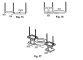
- fig. 15 there are an ordinary seat portion 401, to the side of which an additional, plank-like part 1503 has been fastened with pliable supports, such as chains 704.
- the plank-like part 1503 thus constitutes an ordinary seat portion.
- FIG. 16 illustrates an integrally manufactured seat component with a safety seat portion 202 and an ordinary seat portion 201 displaced from each other in the longitudinal direction of the combination seat thus formed, which longitudinal direction is perpendicular to the swinging direction like in all embodiments described in the previous drawings.
- Fig. 17 illustrates a combination seat according to an embodiment of the invention, in which the ordinary seat portion 201 is a tyre seat attached with cords between two safety seat portions 202. Fig. 17 is also an example of having the sitting heights of the different seat portions differently selected in the combined structure.
- a playground swing according to the invention may have many other kinds of support frames, like such where each end of the horizontal support beam rests on the top of a vertical A-frame, or such that do not have any horizontal support beam but only two individually standing supports, each one defining one or more attachment points for the pliable supports of the swing seat.
- the number of chains or other pliable supports is not necessarily exactly four for three-player swing seats or three for two-player swing seats.
- the safety seat portions may have the lower part and the ring part manufactured integrally in one piece, or they can be assembled from a number of parts.
Landscapes
- Special Chairs (AREA)
- Chairs Characterized By Structure (AREA)
- Chairs For Special Purposes, Such As Reclining Chairs (AREA)
Applications Claiming Priority (1)
| Application Number | Priority Date | Filing Date | Title |
|---|---|---|---|
| FI20070937A FI20070937A7 (fi) | 2007-12-04 | 2007-12-04 | Perhekeinu |
Publications (1)
| Publication Number | Publication Date |
|---|---|
| EP2067510A1 true EP2067510A1 (fr) | 2009-06-10 |
Family
ID=38951474
Family Applications (1)
| Application Number | Title | Priority Date | Filing Date |
|---|---|---|---|
| EP08170543A Withdrawn EP2067510A1 (fr) | 2007-12-04 | 2008-12-03 | Balançoire familiale |
Country Status (3)
| Country | Link |
|---|---|
| EP (1) | EP2067510A1 (fr) |
| KR (1) | KR20090058452A (fr) |
| FI (1) | FI20070937A7 (fr) |
Cited By (7)
| Publication number | Priority date | Publication date | Assignee | Title |
|---|---|---|---|---|
| US9084940B2 (en) | 2013-08-23 | 2015-07-21 | Playcore Wisconsin, Inc. | Swing designed to promote attunement between child and caretaker |
| GB2522268A (en) * | 2014-01-21 | 2015-07-22 | John Szpurko | Recreational swing |
| EP3017851A1 (fr) | 2014-11-04 | 2016-05-11 | HAGS Aneby AB | Siège basculant de génération |
| US10265629B2 (en) | 2017-05-17 | 2019-04-23 | Kompan A/S | Swing for adult and child |
| US10427057B2 (en) | 2017-02-09 | 2019-10-01 | Landscape Structures Inc. | Multi-user swing set |
| USD863486S1 (en) | 2018-01-22 | 2019-10-15 | Playcore Wisconsin, Inc. | Swing seat |
| JP2023114315A (ja) * | 2022-02-04 | 2023-08-17 | 株式会社アネビー | 揺動遊具 |
Families Citing this family (2)
| Publication number | Priority date | Publication date | Assignee | Title |
|---|---|---|---|---|
| KR200460410Y1 (ko) * | 2010-02-10 | 2012-05-24 | 신영태 | 유아용 그네안장 조립체 |
| KR20240000869U (ko) | 2022-11-15 | 2024-05-22 | 장서희 | 그네용 이불 |
Citations (7)
| Publication number | Priority date | Publication date | Assignee | Title |
|---|---|---|---|---|
| FR440339A (fr) * | 1912-02-17 | 1912-07-08 | Fernand Cauet | Appui-bras de voyage |
| US1460843A (en) * | 1922-04-28 | 1923-07-03 | Jeremiah E Brown | Swing |
| US2539869A (en) * | 1945-10-17 | 1951-01-30 | George D Sicklesteel | Combination merry-go-round and swing |
| US3615119A (en) * | 1969-03-28 | 1971-10-26 | Roy L Irwin | Tandem swings |
| US3663016A (en) | 1969-12-08 | 1972-05-16 | Earl R Morris | Swing apparatus |
| GB2195550A (en) | 1986-10-01 | 1988-04-13 | William Ronald Turner | Swing with movable hinge pivots |
| GB2331022A (en) * | 1997-11-05 | 1999-05-12 | Michael John Parker | Swings |
-
2007
- 2007-12-04 FI FI20070937A patent/FI20070937A7/fi not_active IP Right Cessation
-
2008
- 2008-12-01 KR KR1020080120562A patent/KR20090058452A/ko not_active Ceased
- 2008-12-03 EP EP08170543A patent/EP2067510A1/fr not_active Withdrawn
Patent Citations (7)
| Publication number | Priority date | Publication date | Assignee | Title |
|---|---|---|---|---|
| FR440339A (fr) * | 1912-02-17 | 1912-07-08 | Fernand Cauet | Appui-bras de voyage |
| US1460843A (en) * | 1922-04-28 | 1923-07-03 | Jeremiah E Brown | Swing |
| US2539869A (en) * | 1945-10-17 | 1951-01-30 | George D Sicklesteel | Combination merry-go-round and swing |
| US3615119A (en) * | 1969-03-28 | 1971-10-26 | Roy L Irwin | Tandem swings |
| US3663016A (en) | 1969-12-08 | 1972-05-16 | Earl R Morris | Swing apparatus |
| GB2195550A (en) | 1986-10-01 | 1988-04-13 | William Ronald Turner | Swing with movable hinge pivots |
| GB2331022A (en) * | 1997-11-05 | 1999-05-12 | Michael John Parker | Swings |
Cited By (18)
| Publication number | Priority date | Publication date | Assignee | Title |
|---|---|---|---|---|
| US9084940B2 (en) | 2013-08-23 | 2015-07-21 | Playcore Wisconsin, Inc. | Swing designed to promote attunement between child and caretaker |
| US11511203B2 (en) | 2013-08-23 | 2022-11-29 | Playcore Wisconsin, Inc. | Swing designed to promote attunement between child and caretaker |
| US12330076B2 (en) | 2013-08-23 | 2025-06-17 | Playcore Wisconsin, Inc. | Swing designed to promote attunement between child and caretaker |
| US10888793B2 (en) | 2013-08-23 | 2021-01-12 | Playcore Wisconsin, Inc. | Swing designed to promote attunement between child and caretaker |
| US9950265B2 (en) | 2013-08-23 | 2018-04-24 | Playcore Wisconsin, Inc. | Swing designed to promote attunement between child and caretaker |
| US11673065B2 (en) | 2013-08-23 | 2023-06-13 | Playcore Wisconsin, Inc. | Swing designed to promote attunement between child and caretaker |
| US10391411B2 (en) | 2013-08-23 | 2019-08-27 | Playcore Wisconsin, Inc. | Swing designed to promote attunement between child and caretaker |
| GB2522268B (en) * | 2014-01-21 | 2020-11-04 | Szpurko John | Recreational swing |
| GB2522268A (en) * | 2014-01-21 | 2015-07-22 | John Szpurko | Recreational swing |
| US9533231B2 (en) | 2014-11-04 | 2017-01-03 | Playpower, Inc. | Swing seat |
| EP3017851A1 (fr) | 2014-11-04 | 2016-05-11 | HAGS Aneby AB | Siège basculant de génération |
| US10427057B2 (en) | 2017-02-09 | 2019-10-01 | Landscape Structures Inc. | Multi-user swing set |
| US10265629B2 (en) | 2017-05-17 | 2019-04-23 | Kompan A/S | Swing for adult and child |
| US10905964B2 (en) | 2017-05-17 | 2021-02-02 | Kompan A/S | Swing for adult and child |
| USD863486S1 (en) | 2018-01-22 | 2019-10-15 | Playcore Wisconsin, Inc. | Swing seat |
| USD919032S1 (en) | 2018-01-22 | 2021-05-11 | Playcore Wisconsin, Inc. | Swing seat |
| JP2023114315A (ja) * | 2022-02-04 | 2023-08-17 | 株式会社アネビー | 揺動遊具 |
| JP7805623B2 (ja) | 2022-02-04 | 2026-01-26 | 株式会社アネビー | 揺動遊具 |
Also Published As
| Publication number | Publication date |
|---|---|
| FI20070937A0 (fi) | 2007-12-04 |
| FI20070937L (fi) | 2009-06-05 |
| KR20090058452A (ko) | 2009-06-09 |
| FI20070937A7 (fi) | 2009-06-05 |
Similar Documents
| Publication | Publication Date | Title |
|---|---|---|
| EP2067510A1 (fr) | Balançoire familiale | |
| KR101731796B1 (ko) | 팔 다리 복합 운동이 가능한 놀이터 적용 안전 유희 구조물 | |
| KR200440648Y1 (ko) | 유아용 조립식 매트 | |
| KR101855415B1 (ko) | 네트 놀이대 | |
| US4251069A (en) | Child recreation structure | |
| US6764408B1 (en) | Inflatable structure with suspended features | |
| US8317631B2 (en) | Seated self-propelled merry-go-round | |
| CN211724656U (zh) | 一种小熊主题游乐设施 | |
| US9403098B1 (en) | Polygonal swing assembly | |
| KR200219067Y1 (ko) | 완구용 그네의 로프 안전 지지구 | |
| JP7390515B1 (ja) | ロデオブランコ | |
| CN208405896U (zh) | 一种互动晃板健身装置 | |
| CN105457277B (zh) | 一种旋转儿童娱乐装置 | |
| CN104399250A (zh) | 一种健身玩具 | |
| CN205164119U (zh) | 一种多功能跷跷板 | |
| CN211883047U (zh) | 一种休闲娱乐用亲子秋千椅 | |
| US5615900A (en) | Toy | |
| KR102190107B1 (ko) | 2인 협력식 익사이팅 체험시설 | |
| CN215538382U (zh) | 具有跷跷板结构的树形儿童游乐设备 | |
| CN2474198Y (zh) | 翘翘杆健身器 | |
| CN209865278U (zh) | 一种具有声光电功能的户外游乐组合设施 | |
| JP5258727B2 (ja) | 壁面運動装置 | |
| CN201418981Y (zh) | 晃动平衡木 | |
| KR200329196Y1 (ko) | 종합놀이대 | |
| KR101057979B1 (ko) | 어린이 놀이기구 |
Legal Events
| Date | Code | Title | Description |
|---|---|---|---|
| PUAI | Public reference made under article 153(3) epc to a published international application that has entered the european phase |
Free format text: ORIGINAL CODE: 0009012 |
|
| AK | Designated contracting states |
Kind code of ref document: A1 Designated state(s): AT BE BG CH CY CZ DE DK EE ES FI FR GB GR HR HU IE IS IT LI LT LU LV MC MT NL NO PL PT RO SE SI SK TR |
|
| AX | Request for extension of the european patent |
Extension state: AL BA MK RS |
|
| RIN1 | Information on inventor provided before grant (corrected) |
Inventor name: LINNA, SAARA |
|
| 17P | Request for examination filed |
Effective date: 20091210 |
|
| AKX | Designation fees paid |
Designated state(s): AT BE BG CH CY CZ DE DK EE ES FI FR GB GR HR HU IE IS IT LI LT LU LV MC MT NL NO PL PT RO SE SI SK TR |
|
| 17Q | First examination report despatched |
Effective date: 20110704 |
|
| STAA | Information on the status of an ep patent application or granted ep patent |
Free format text: STATUS: THE APPLICATION IS DEEMED TO BE WITHDRAWN |
|
| 18D | Application deemed to be withdrawn |
Effective date: 20111115 |