EP2067514A2 - Système de carburant et assemblage de filtre de carburant - Google Patents
Système de carburant et assemblage de filtre de carburant Download PDFInfo
- Publication number
- EP2067514A2 EP2067514A2 EP08019870A EP08019870A EP2067514A2 EP 2067514 A2 EP2067514 A2 EP 2067514A2 EP 08019870 A EP08019870 A EP 08019870A EP 08019870 A EP08019870 A EP 08019870A EP 2067514 A2 EP2067514 A2 EP 2067514A2
- Authority
- EP
- European Patent Office
- Prior art keywords
- filter
- standpipe
- fuel
- assembly
- housing
- Prior art date
- Legal status (The legal status is an assumption and is not a legal conclusion. Google has not performed a legal analysis and makes no representation as to the accuracy of the status listed.)
- Withdrawn
Links
Images

Classifications
-
- B—PERFORMING OPERATIONS; TRANSPORTING
- B01—PHYSICAL OR CHEMICAL PROCESSES OR APPARATUS IN GENERAL
- B01D—SEPARATION
- B01D35/00—Filtering devices having features not specifically covered by groups B01D24/00 - B01D33/00, or for applications not specifically covered by groups B01D24/00 - B01D33/00; Auxiliary devices for filtration; Filter housing constructions
- B01D35/14—Safety devices specially adapted for filtration; Devices for indicating clogging
- B01D35/147—Bypass or safety valves
-
- B—PERFORMING OPERATIONS; TRANSPORTING
- B01—PHYSICAL OR CHEMICAL PROCESSES OR APPARATUS IN GENERAL
- B01D—SEPARATION
- B01D35/00—Filtering devices having features not specifically covered by groups B01D24/00 - B01D33/00, or for applications not specifically covered by groups B01D24/00 - B01D33/00; Auxiliary devices for filtration; Filter housing constructions
- B01D35/14—Safety devices specially adapted for filtration; Devices for indicating clogging
- B01D35/153—Anti-leakage or anti-return valves
-
- F—MECHANICAL ENGINEERING; LIGHTING; HEATING; WEAPONS; BLASTING
- F02—COMBUSTION ENGINES; HOT-GAS OR COMBUSTION-PRODUCT ENGINE PLANTS
- F02M—SUPPLYING COMBUSTION ENGINES IN GENERAL WITH COMBUSTIBLE MIXTURES OR CONSTITUENTS THEREOF
- F02M37/00—Apparatus or systems for feeding liquid fuel from storage containers to carburettors or fuel-injection apparatus; Arrangements for purifying liquid fuel specially adapted for, or arranged on, internal-combustion engines
- F02M37/22—Arrangements for purifying liquid fuel specially adapted for, or arranged on, internal-combustion engines, e.g. arrangements in the feeding system
- F02M37/32—Arrangements for purifying liquid fuel specially adapted for, or arranged on, internal-combustion engines, e.g. arrangements in the feeding system characterised by filters or filter arrangements
- F02M37/48—Filters structurally associated with fuel valves
-
- F—MECHANICAL ENGINEERING; LIGHTING; HEATING; WEAPONS; BLASTING
- F02—COMBUSTION ENGINES; HOT-GAS OR COMBUSTION-PRODUCT ENGINE PLANTS
- F02M—SUPPLYING COMBUSTION ENGINES IN GENERAL WITH COMBUSTIBLE MIXTURES OR CONSTITUENTS THEREOF
- F02M37/00—Apparatus or systems for feeding liquid fuel from storage containers to carburettors or fuel-injection apparatus; Arrangements for purifying liquid fuel specially adapted for, or arranged on, internal-combustion engines
- F02M37/22—Arrangements for purifying liquid fuel specially adapted for, or arranged on, internal-combustion engines, e.g. arrangements in the feeding system
- F02M37/54—Arrangements for purifying liquid fuel specially adapted for, or arranged on, internal-combustion engines, e.g. arrangements in the feeding system characterised by air purging means
-
- B—PERFORMING OPERATIONS; TRANSPORTING
- B01—PHYSICAL OR CHEMICAL PROCESSES OR APPARATUS IN GENERAL
- B01D—SEPARATION
- B01D2201/00—Details relating to filtering apparatus
- B01D2201/31—Other construction details
- B01D2201/316—Standpipes
-
- F—MECHANICAL ENGINEERING; LIGHTING; HEATING; WEAPONS; BLASTING
- F02—COMBUSTION ENGINES; HOT-GAS OR COMBUSTION-PRODUCT ENGINE PLANTS
- F02M—SUPPLYING COMBUSTION ENGINES IN GENERAL WITH COMBUSTIBLE MIXTURES OR CONSTITUENTS THEREOF
- F02M2200/00—Details of fuel-injection apparatus, not otherwise provided for
- F02M2200/27—Fuel-injection apparatus with filters
-
- F—MECHANICAL ENGINEERING; LIGHTING; HEATING; WEAPONS; BLASTING
- F02—COMBUSTION ENGINES; HOT-GAS OR COMBUSTION-PRODUCT ENGINE PLANTS
- F02M—SUPPLYING COMBUSTION ENGINES IN GENERAL WITH COMBUSTIBLE MIXTURES OR CONSTITUENTS THEREOF
- F02M37/00—Apparatus or systems for feeding liquid fuel from storage containers to carburettors or fuel-injection apparatus; Arrangements for purifying liquid fuel specially adapted for, or arranged on, internal-combustion engines
- F02M37/0047—Layout or arrangement of systems for feeding fuel
- F02M37/0052—Details on the fuel return circuit; Arrangement of pressure regulators
-
- F—MECHANICAL ENGINEERING; LIGHTING; HEATING; WEAPONS; BLASTING
- F02—COMBUSTION ENGINES; HOT-GAS OR COMBUSTION-PRODUCT ENGINE PLANTS
- F02M—SUPPLYING COMBUSTION ENGINES IN GENERAL WITH COMBUSTIBLE MIXTURES OR CONSTITUENTS THEREOF
- F02M63/00—Other fuel-injection apparatus having pertinent characteristics not provided for in groups F02M39/00 - F02M57/00 or F02M67/00; Details, component parts, or accessories of fuel-injection apparatus, not provided for in, or of interest apart from, the apparatus of groups F02M39/00 - F02M61/00 or F02M67/00; Combination of fuel pump with other devices, e.g. lubricating oil pump
- F02M63/02—Fuel-injection apparatus having several injectors fed by a common pumping element, or having several pumping elements feeding a common injector; Fuel-injection apparatus having provisions for cutting-out pumps, pumping elements, or injectors; Fuel-injection apparatus having provisions for variably interconnecting pumping elements and injectors alternatively
- F02M63/0225—Fuel-injection apparatus having a common rail feeding several injectors ; Means for varying pressure in common rails; Pumps feeding common rails
Definitions
- the present invention relates generally to fuel systems and filter assemblies for vehicle engines, and more particularly, to an improved fuel system and an improved filter assembly that simplify filter service/replacement.
- filter assemblies typically include a filter with a filter element that is disposed around a standpipe.
- the filter is used to remove dirt and debris from the fuel to prevent the contaminants from entering the standpipe opening, which is the passage for clean fuel to the fuel rail. When the filter elements are spent, the filter assembly must be serviced.
- the filter While servicing the filter and/or standpipe, the filter is removed from the standpipe resulting in the standpipe openings being exposed. While the filter is removed during service, there is a tendency by the user to fill the filter housing with fuel, which has dirt and debris that clings to the sides of the standpipe and that can also enter the standpipe openings. If the contaminants enter the standpipe, the contaminants can potentially cause the components of the fuel system to fail.
- One way to avoid the dirty fuel from dripping onto the standpipe is to evacuate the supply and return fuel lines, however this requires effort by the user and is time consuming.
- the filter is located in a filter housing, which forms a chamber around the filter. Frequently, air is trapped in a portion of the chamber that is located between a top plate of the filter and an internal surface of a housing cap. De-aeration can be performed manually, requiring intervention from a user.
- an air bleed orifice can be included on the filter.
- a conventional air bleed orifice allows the pressurized fuel to bleed back to the tank, which when the engine is not running, allows the pressure in the chamber to return to atmospheric pressure. Since the pressure is not regulated when the engine is not running, there is a relatively long engine crank-to-start time because the pressure has to build within the system before the engine will start.
- a filter assembly for a standpipe having an opening for the introduction of filtered fluid into the standpipe includes a filter.
- the filter has a filter element in fluid communication with the opening.
- the filter is configured to seal fluid from the opening except fluid flowing through the filter element.
- a valve assembly is biased by a spring against a first surface of the filter, and the valve assembly has a seal on a surface facing the standpipe. As the filter is displaced, the valve assembly displaces along the standpipe under bias of the spring until the seal of the valve assembly seals the opening.
- FIG. 1 is a side section view of a filter assembly in accordance with the invention.
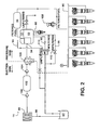
- FIG. 2 is a circuit diagram of a fuel system in accordance with the invention.
- a filter assembly is indicated generally at 10 and includes a generally cylindrical filter 12 disposed around a generally cylindrical standpipe 14.
- the filter 12 has a center tube 16 configured to generally circumscribe the standpipe 14, and a filter element 18 disposed about the center tube.
- the filter 12 is configured to remove dirt and debris from the fuel in fluid communication with openings 20 in the standpipe 14.
- the filter 12 is disposed in a housing 22 having a first portion 24 and a second portion 26.
- An apron 28 of the standpipe 14 sealingly contacts the second portion 26 of the housing 22, and a cap 30 is threadably received by the first portion 24 to form a chamber 32.
- An inlet 34 is located in the first portion 24 of the housing 22 for receiving fuel, which flows into the chamber 32 and through the filter 12 to the standpipe 14. When the fuel reaches the standpipe openings 20, the contaminants are removed by the filter element 18. The fuel then flows through the standpipe 14 and out an outlet 36.
- An internal surface 38 of the cap 30 contacts a first plate 40 of the filter 12, while a valve assembly 42 contacts a second plate 44 on the opposite side of the filter 12.
- the valve assembly 42 is biased by a spring 46 that pushes the filter 12 along the axis "A" of the standpipe 14 and into engagement with the cap 30.
- the valve assembly 42 includes a valve member 48 having a first component 50 sealingly contacting the second portion 26 of the housing 22, a second component 52 extending generally perpendicular to the first component, a third component 54 in engagement with the second plate 44 of the filter 12 and generally perpendicular to the second component, and a fourth component 56 generally parallel with and sealingly contacting the standpipe 14.
- the spring 46 is disposed between the second component 52 and the fourth component 56, and generally circumscribes the standpipe 14.
- a filter assembly when the filter is removed from the standpipe for servicing, the filter is no longer in place to prevent dirty fuel from entering the standpipe openings.
- the valve assembly 42 slides along the standpipe 14 under bias of the spring 46 until the fourth component 56 of the valve assembly 42 covers the standpipe openings 20.
- a molded dynamic seal 58 is disposed on an inner surface of the fourth component 56 for sealing the standpipe openings 20, however other configurations are contemplated.
- An additional seal 62 is disposed on the second plate 44 where the second plate contacts the standpipe 14 and the valve assembly 42, which prevents unfiltered fuel from contacting the standpipe in the vicinity of the standpipe openings 20.
- valve assembly 42 When the valve assembly 42 seals the standpipe openings 20, the first component 50 of the valve member 48 is displaced away from and out of sealing engagement with the second portion 26 of the housing 22. In the unseated position, a passage 64 is opened to allow fuel to drain out of an outlet 66 to return to a fuel tank 67. With the filter assembly 10, fuel will not flow to the outlet 36 and the engine will not run without the filter 12 being in place about the standpipe openings 20.
- the inner seal 62 on the center tube and the second plate 44 slides along the standpipe 14 and scrapes away any dirt or debris stuck on the standpipe.
- the second plate 44 pushes against the bias of the spring 46 of the valve assembly 42 until the first component 50 is seated on the second portion 26 of the housing 22.
- the cap 30 is threadably attached to the housing 22 and the internal surface 38 contacts the filter 12 to ensure sealing of the filter, the valve assembly 42, the standpipe 14 and the housing 22 to prevent unfiltered fuel from reaching the standpipe openings 20.
- a check valve 68 is provided at the inlet 34 located in the first portion 24 of the housing 22. Also located on the first portion 24 of the housing 22 is an air bleed orifice 70 that is in fluid communication with an air bleed passageway 72.
- the air bleed orifice 70 is formed by the internal cap surface 38 and a distal surface 74 of an inner housing member 76, and the air bleed passageway 72 is formed between the inner housing member and an outer housing member 78.
- the outer housing member 78 is generally parallel to the inner housing member 76.
- the regulator valve 80 At the end of the air bleed passageway 72 is a regulator valve 80 with a seal 82.
- the regulator valve 80 includes a plate 84 having the seal 82 integral with the plate, where the plate is biased by a spring 86 against both the second portion 26, the inner housing member 76 and the outer housing member 78 to seal the air bleed passageway 72.
- the seal 82 is configured to seal the air bleed passageway 72 from the outlet 66 that returns fuel to the tank 67.
- the pressure developed in the filter assembly 10 opens the regulator valve 80 against the bias of the spring 86 to let the air bleed through the air bleed passageway 72 to the outlet 66.
- the air bleed passageway 72 efficiently and automatically removes air from a fuel system 11 during engine startup, such as after servicing/replacing the fuel filter 12.
- the check valve 68 and the regulator valve 80 prevent fuel from exiting the housing 22. Further, the check valve 68 and the regulator valve 80 maintain the pressure in the housing 22 above atmospheric pressure when the engine is not running. When the higher fuel pressure is maintained, there is a quicker crank-to-start time in the fuel system than in a conventional system where the pressure has to build within the system. Additionally, the higher fuel pressure gets released during removal of the filter 12 when the passage 64 is opened to drain the fuel out the outlet 66 back to the tank 67.
- the fuel system 11 includes a fuel supply circuit 88 for delivering fuel from the tank 67 to a fuel rail (and/or engine) 90, a fuel return circuit 92 for returning fuel from the fuel filter assembly 10 to the tank 67, a fuel air bleed circuit 94 for bleeding air from the fuel filter assembly 10, and a drain-to-tank circuit 96 for draining fuel from the fuel filter assembly 10 to the tank 67.
- the fuel supply circuit 88 includes a fuel strainer 98, a first check valve 100, a primer pump 102, and a second check valve 104 upstream of a fuel pump 106. From the fuel pump, the pressurized fuel enters the fuel filter assembly 10 and is filtered at the fuel filter 12. The filtered fuel flows through the standpipe 14 and exits the outlet 36 to flow to the fuel rail 90.
- a fuel pressure sensor 108 senses the pressure of the fuel before it reaches the fuel rail 90.
- a fuel pressure regulator valve 110 opens to return excess unfiltered fuel to the fuel tank 67 along the return circuit 92. It is contemplated that other predetermined pressures can be used.
- the drain-to-tank circuit 96 includes the passage 64, which is automatically opened during service/replacement of the filter 12, to allow unfiltered fuel to drain out of an outlet 66 to return to a fuel tank 67.
- the drain-to-tank circuit 96 is operable without pressure built up in the fuel system 11, i.e. without the engine running.
- the drain-to-tank circuit 96 can include a gate valve 112.
- the air bleed circuit 94 includes the air bleed passageway 72 and the regulator valve 80.
- the pressure developed in the filter assembly 10 opens the regulator valve 80 to let the air bleed through the air bleed passageway 72 to the fuel tank 67.
- the air bleed circuit 94 obviates the need for a user to manually de-aerate the fuel system 11. Further, the fuel system 11 increases the life of the filter 12 by filtering only the fuel that is burned in the engine, and not the fuel that is returned to the fuel tank 67.
Landscapes
- Engineering & Computer Science (AREA)
- Chemical & Material Sciences (AREA)
- Combustion & Propulsion (AREA)
- Mechanical Engineering (AREA)
- General Engineering & Computer Science (AREA)
- Chemical Kinetics & Catalysis (AREA)
- Filtration Of Liquid (AREA)
Applications Claiming Priority (1)
| Application Number | Priority Date | Filing Date | Title |
|---|---|---|---|
| US11/949,077 US20090139920A1 (en) | 2007-12-03 | 2007-12-03 | Fuel system and fuel filter assembly |
Publications (2)
| Publication Number | Publication Date |
|---|---|
| EP2067514A2 true EP2067514A2 (fr) | 2009-06-10 |
| EP2067514A3 EP2067514A3 (fr) | 2010-10-20 |
Family
ID=40456863
Family Applications (1)
| Application Number | Title | Priority Date | Filing Date |
|---|---|---|---|
| EP08019870A Withdrawn EP2067514A3 (fr) | 2007-12-03 | 2008-11-13 | Système de carburant et assemblage de filtre de carburant |
Country Status (5)
| Country | Link |
|---|---|
| US (1) | US20090139920A1 (fr) |
| EP (1) | EP2067514A3 (fr) |
| BR (1) | BRPI0805383A2 (fr) |
| CA (1) | CA2643850A1 (fr) |
| MX (1) | MX2008014914A (fr) |
Cited By (1)
| Publication number | Priority date | Publication date | Assignee | Title |
|---|---|---|---|---|
| WO2017129896A1 (fr) * | 2016-01-29 | 2017-08-03 | Sogefi Filtration | Filtre à carburant et support de montage dont la sortie est obturée par un clapet en cas de retrait d'un insert filtrant |
Families Citing this family (7)
| Publication number | Priority date | Publication date | Assignee | Title |
|---|---|---|---|---|
| US9028702B2 (en) * | 2011-09-20 | 2015-05-12 | Baldwin Filters, Inc. | Fuel filter with snorkel vent |
| CN102588171B (zh) * | 2012-03-20 | 2013-09-18 | 张银科 | 电控排气柴油滤清器 |
| WO2013155427A1 (fr) * | 2012-04-13 | 2013-10-17 | Cummins Filtration Ip, Inc. | Élément filtrant ayant une purge d'air automatique |
| US9359962B2 (en) | 2012-04-25 | 2016-06-07 | International Engine Intellectual Property Company, Llc | Engine braking |
| JP6398856B2 (ja) * | 2015-04-24 | 2018-10-03 | 京三電機株式会社 | 燃料フィルタ |
| US11846246B2 (en) * | 2021-05-27 | 2023-12-19 | Thermo King Llc | Methods and systems for controlling engine inlet pressure via a fuel delivery system of a transport climate control system |
| USD1091777S1 (en) | 2022-06-28 | 2025-09-02 | Thomas J. Henne | Elbow fitting |
Family Cites Families (8)
| Publication number | Priority date | Publication date | Assignee | Title |
|---|---|---|---|---|
| US5855780A (en) * | 1996-11-04 | 1999-01-05 | Advanced Performance Technology, Inc. | Fuel filter element with flow actuator |
| US6270659B1 (en) * | 1999-07-02 | 2001-08-07 | Fleetguard, Inc. | Fuel filtering system for an engine |
| US6495042B1 (en) * | 1999-12-03 | 2002-12-17 | Parker-Hannifin Corporation | Filter cartridge for a fuel filter having a keyed latch shut-off valve |
| ES2195946T3 (es) * | 1999-12-03 | 2003-12-16 | Parker Hannifin Corp | Valvula con pestillo de enganche para filtro de carburante. |
| US7572306B2 (en) * | 2004-09-15 | 2009-08-11 | Cummins Filtration Ip Inc. | Filter system integrating pressure regulation and air vent |
| US7392783B2 (en) * | 2005-10-17 | 2008-07-01 | Mahle International Gmbh | Internal combustion engine, especially in a motor vehicle, having a fuel filter system |
| CA2584927C (fr) * | 2006-04-13 | 2011-02-08 | Wix Filtration Corp. | Organe servant a actionner la colonne montante d'un element filtrant remplacable |
| US20080169233A1 (en) * | 2007-01-11 | 2008-07-17 | Joma-Polytec Kunststofftechnik Gmbh | Oil filter assembly |
-
2007
- 2007-12-03 US US11/949,077 patent/US20090139920A1/en not_active Abandoned
-
2008
- 2008-11-13 EP EP08019870A patent/EP2067514A3/fr not_active Withdrawn
- 2008-11-14 CA CA002643850A patent/CA2643850A1/fr not_active Abandoned
- 2008-11-24 MX MX2008014914A patent/MX2008014914A/es not_active Application Discontinuation
- 2008-12-03 BR BRPI0805383-9A patent/BRPI0805383A2/pt not_active Application Discontinuation
Cited By (3)
| Publication number | Priority date | Publication date | Assignee | Title |
|---|---|---|---|---|
| WO2017129896A1 (fr) * | 2016-01-29 | 2017-08-03 | Sogefi Filtration | Filtre à carburant et support de montage dont la sortie est obturée par un clapet en cas de retrait d'un insert filtrant |
| FR3047183A1 (fr) * | 2016-01-29 | 2017-08-04 | Sogefi Filtration France | Filtre a carburant et support de montage dont la sortie est obturee par un clapet en cas de retrait d'un insert filtrant |
| US11338230B2 (en) | 2016-01-29 | 2022-05-24 | Sogefi Filtration | Fuel filter and mounting support of which the outlet is sealed by a valve in case of removal of a filter insert |
Also Published As
| Publication number | Publication date |
|---|---|
| EP2067514A3 (fr) | 2010-10-20 |
| US20090139920A1 (en) | 2009-06-04 |
| CA2643850A1 (fr) | 2009-06-03 |
| BRPI0805383A2 (pt) | 2009-09-08 |
| MX2008014914A (es) | 2009-09-03 |
Similar Documents
| Publication | Publication Date | Title |
|---|---|---|
| EP2067514A2 (fr) | Système de carburant et assemblage de filtre de carburant | |
| US4500425A (en) | Pump valve for liquid separator | |
| EP1653075B1 (fr) | Dispositif d'évacuation automatique de l'eau pour un séparateur de carburant et d'eau | |
| AU719225B2 (en) | Self-evacuating water-separating fuel filter | |
| US7210465B2 (en) | Fuel supply device for fuel returnless system | |
| DE112009000563B4 (de) | Flüssigkeitsfiltervorrichtung mit Standrohr mit integriertem Regelventil und Verfahren mit dieser Flüssigkeitsfiltervorrichtung | |
| US20030127384A1 (en) | Filter module for aircraft lubrication systems | |
| US20020100720A1 (en) | Filter arrangement for liquids | |
| US5578221A (en) | Fuel filter with improved hand primer | |
| US6019890A (en) | Fuel filter with hand primer | |
| US20160332095A1 (en) | Filtration System with Anti Drain Valve and Drain X-Seal | |
| US20220241704A1 (en) | No filter no run fluid filter with integration of low pressure fluid system | |
| US7938958B2 (en) | De-aeration system | |
| US5584318A (en) | Modular fuel filter and pressure regulator apparatus | |
| US20050133430A1 (en) | Fuel pump module having a fuel filter water drain | |
| US20200368652A1 (en) | No filter no run fluid filtration system | |
| US20240033665A1 (en) | Filter valve assembly | |
| US20150265948A1 (en) | Reinforced oil filter check valve | |
| US20020189710A1 (en) | Filler cup for fluid filter | |
| US6637551B2 (en) | Check ball filter for transmissions | |
| US11448173B2 (en) | Return tube of a fuel filter assembly of a fuel system | |
| US20090095665A1 (en) | Anti-Drainback Valve For An Oil Filter | |
| WO2016170716A1 (fr) | Filtre à carburant | |
| US5820356A (en) | Power steering pump apparatus | |
| US20090145825A1 (en) | Filter Arrangement for Liquids |
Legal Events
| Date | Code | Title | Description |
|---|---|---|---|
| PUAI | Public reference made under article 153(3) epc to a published international application that has entered the european phase |
Free format text: ORIGINAL CODE: 0009012 |
|
| AK | Designated contracting states |
Kind code of ref document: A2 Designated state(s): AT BE BG CH CY CZ DE DK EE ES FI FR GB GR HR HU IE IS IT LI LT LU LV MC MT NL NO PL PT RO SE SI SK TR |
|
| AX | Request for extension of the european patent |
Extension state: AL BA MK RS |
|
| RIN1 | Information on inventor provided before grant (corrected) |
Inventor name: DICKERSON, STEVEN J. Inventor name: DHAWALE, SAMIR D. |
|
| PUAL | Search report despatched |
Free format text: ORIGINAL CODE: 0009013 |
|
| AK | Designated contracting states |
Kind code of ref document: A3 Designated state(s): AT BE BG CH CY CZ DE DK EE ES FI FR GB GR HR HU IE IS IT LI LT LU LV MC MT NL NO PL PT RO SE SI SK TR |
|
| AX | Request for extension of the european patent |
Extension state: AL BA MK RS |
|
| 17P | Request for examination filed |
Effective date: 20110420 |
|
| AKX | Designation fees paid |
Designated state(s): AT BE BG CH CY CZ DE DK EE ES FI FR GB GR HR HU IE IS IT LI LT LU LV MC MT NL NO PL PT RO SE SI SK TR |
|
| 17Q | First examination report despatched |
Effective date: 20120123 |
|
| STAA | Information on the status of an ep patent application or granted ep patent |
Free format text: STATUS: THE APPLICATION IS DEEMED TO BE WITHDRAWN |
|
| 18D | Application deemed to be withdrawn |
Effective date: 20120601 |